Project 2 Adaptive Cruise Control
Aim:
To implement the Adaptive Cruise Control of the vehicle using matlab Simulink and generate the code.
Objective:
- Developing Adaptive Cruise Control feature as per the Requirement Document using MATLAB Simulink.
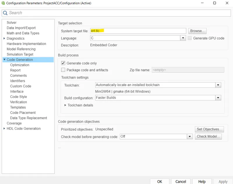
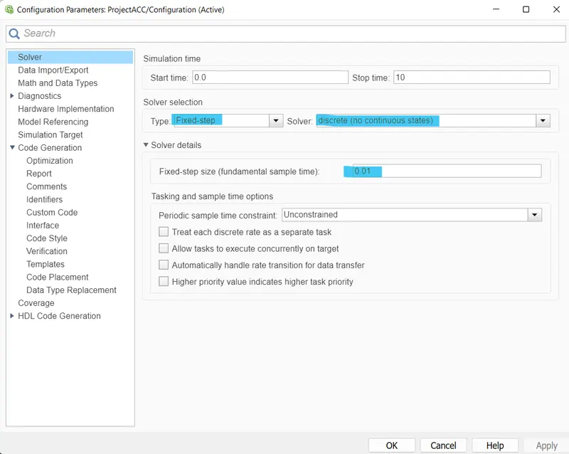
- Follow all the MBD-related processes: Requirement Tagging & Traceability, SLDD creation, Configuration Parameter changes, Model Advisor check & Code Generation.
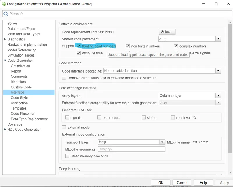
- In Configuration Parameters: enable “Support Floating Numbers” under Code Generation settings.
- Use Embedded Coder to generate the code.
- If choosing code generation, Storage class for Input signals: ImportedExtern; Storage class for Output signal: Export to File; Storage class for local signals: localizable; Storage class for calibration signals: Const.
- Choose sample time for all signals as 0.01s
Adaptive Cruise Control(ACC):
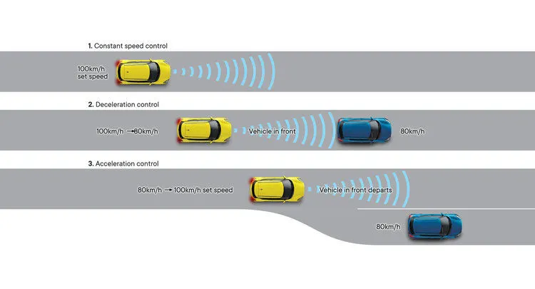
ACC will automatically adjust the vehicle speed to maintain a safe distance from vehicles ahead.
If there are no vehicles ahead, then it maintains a constant speed. If there is a vehicle ahead and its speed is sensed then the driver vehicle also runs at the same speed as the lead vehicle. If the lead vehicle changes its lane then the driver's vehicle speed will be increased to its constant speed level.
Simulink Model: attached and named ProjectACC.slx
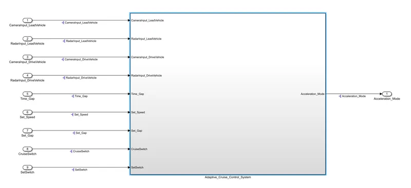
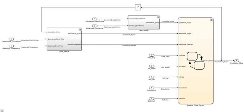
Create a model as per the requirement, In this project, we have to implement the 3 requirements that are named Lead vehicle, Driver vehicle, and Adaptive Cruise Control.
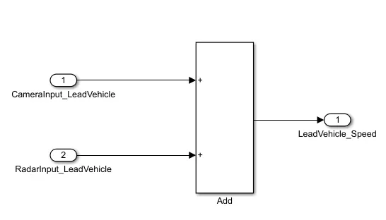
Requirement 1: Lead vehicle
CameraInput_LeadVehicle & RadarInput_LeadVehicle are the input signal which is taken from the lead vehicle(The vehicle which is driving on the road ahead of our drive vehicle). By adding the input signal we will get the lead vehicle speed as output(Which is going to connect with the state machine logic).
Requirement 2: Drive Vehicle
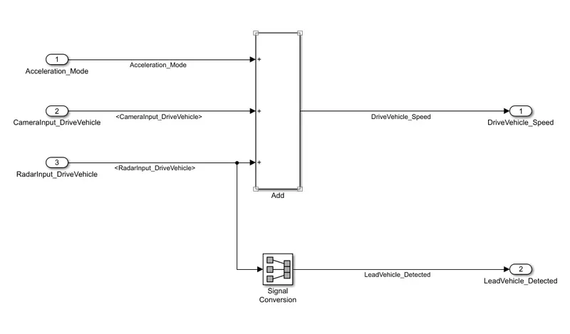
There are 3 inputs in this subsystem named CameraInput DriveVehicle, RadarInput DriveVehicle, and Acceleration on, and two outputs named Drivervehicle speed and lead vehicle detected.
CameraInput DriveVehicle and RadarInput DriveVehicle are the signals which are taken from the drive vehicle and Acceleration ON is a signal which is feedback from ACC state flow.
We get Driver's vehicle speed by summing all three inputs and the Radar input Drive vehicle signal is directly converted to the lead vehicle signal through the signal conversation block
Requirement 3: Adaptive Cruise Control Algorithm
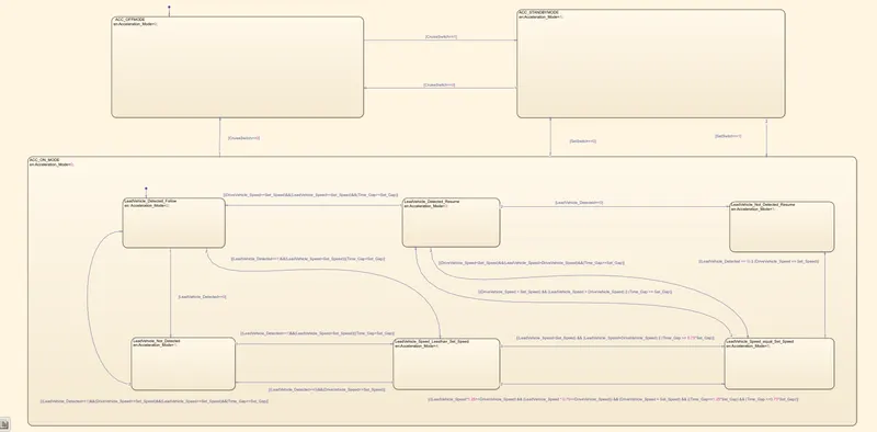
3 modes are in the state machine, they are ACC off, Standby, and on
ACC OFF MODE: It is the default state inside the state machine logic. Output signal Acceleration_Mode is at value 0. This state is controlled by the input signal CruiseSwitch. If CruiseSwitch is equal to 1, state ACC STANDBY mode will get activated. If CruiseSwitch is equal to 0, state ACC OFF mode will get activated, from either ACC ON mode or ACC STANDBY mode
ACC STANDBY MODE: Output signal Acceleration_Mode is at value 1 in this state. This state is governed by both input signals CruiseSwitch & SetSwitch.
- If CruiseSwitch = 1, ACC STANDBY mode. If CruiseSwitch = 0, ACC OFF mode, from either ACC ON mode or ACC STANDBY mode
- If SetSwitch=1, state ACC ON mode. If SetSwitch = 0, ACC STANDBY mode.
ACC ON MODE:
Input signal SetSwitch = 1. There are 6 sub-states to this state logic: They are:
- LeadVehicle_Detected_Follow (Default)
- LeadVehicle_Not_Detected
- LeadVehicle_Detected_Resume
- LeadVehicle_Not_Detected_Resume
- LeadVehicle_Speed_lessthan_Set_Speed
- LeadVehicle_Speed_equal_Set_Speed
LeadVehicle_Detected_Follow (ACC ON MODE):
Default sub-state inside ACC ON MODE state. Output signal Acceleration_Mode = 2.
LeadVehicle_Detected_Follow to LeadVehicle_Not_Detected;
- Input condition LeadVehicle_Detected == 0.
LeadVehicle_Detected_Follow to LeadVehicle_Speed_lessthan_Set_Speed;
- Input Signals condition (LeadVehicle_Detected == 1) && (LeadVehicle_Speed < Set_Speed) || (Time_Gap < Set_Gap).
LeadVehicle_Not_Detected (ACC ON MODE):
- Output signal Acceleration_Mode = 1.
LeadVehicle_Not_Detected to LeadVehicle_Detected_Follow;
- Input signals condition [(LeadVehicle_Detected==1) && (DriveVehicle_Speed == Set_Speed) && (LeadVehicle_Speed >= Set_Speed) && (Time_Gap >= Set_Gap)]
LeadVehicle_Not_Detected to LeadVehicle_Speed_lessthan_Set_Speed;
- Input signals condition [(LeadVehicle_Detected == 1) && (LeadVehicle_Speed < Set_Speed) || (Time_Gap < Set_Gap)]
LeadVehicle_Detected_Resume (ACC ON MODE):
- Output signal Acceleration_Mode=3.
LeadVehicle_Detected_Resume to LeadVehicle_Detected_Follow;
- Input signals condition [(DriveVehicle_Speed == Set_Speed) && (LeadVehicle_Speed >= Set_Speed) && (Time_Gap >= Set_Gap)]
LeadVehicle_Detected_Resume to LeadVehicle_Not_Detected_Resume;
- Input signal condition LeadVehicle_Detected==0.
LeadVehicle_Detected_Resume to LeadVehicle_Speed_equal_Set_Speed;
- Input Signal condition [(DriveVehicle_Speed < Set_Speed) && (LeadVehicle_Speed > DriveVehicle_Speed) && (Time_Gap >= Set_Gap)]
LeadVehicle_Not_Detected_Resume (ACC ON MODE):
- Output signal Acceleration_Mode = 1.
LeadVehicle_Speed_lessthan_Set_Speed (ACC ON MODE):
- Output signal Acceleration_Mode = 4.
LeadVehicle_Speed_lessthan_Set_Speed to LeadVehicle_Not_Detected;
- Input signal condition [(LeadVehicle_Detected == 0) && (DriveVehicle_Speed == Set_Speed)]
LeadVehicle_Speed_lessthan_Set_Speed to LeadVehicle_Speed_equal_Set_Speed;
- Input signals condition [((LeadVehicle_Speed*1.25>=DriveVehicle_Speed) && (LeadVehicle_Speed * 0.75<=DriveVehicle_Speed)) && (DriveVehicle_Speed < Set_Speed) && ((Time_Gap<=1.25*Set_Gap) && (Time_Gap >=0.75*Set_Gap))]
LeadVehicle_Speed_equal_Set_Speed (ACC ON MODE):
- Output signal Acceleration_Mode = 5.
LeadVehicle_Speed_equal_Set_Speed to LeadVehicle_Not_Detected_Resume;
- Input signal conditions is [(LeadVehicle_Detected == 0) || (DriveVehicle_Speed <= Set_Speed)]
LeadVehicle_Speed_equal_Set_Speed to LeadVehicle_Detected_Resume;
- Input signal conditions [(DriveVehicle_Speed < Set_Speed) && (LeadVehicle_Speed > DriveVehicle_Speed) || (Time_Gap >= Set_Gap)]
LeadVehicle_Speed_equal_Set_Speed to LeadVehicle_Speed_lessthan_Set_Speed;
- Input signals conditions [(LeadVehicle_Speed<Set_Speed) && (LeadVehicle_Speed<DriveVehicle_Speed) || (Time_Gap == 0.75*Set_Gap)]
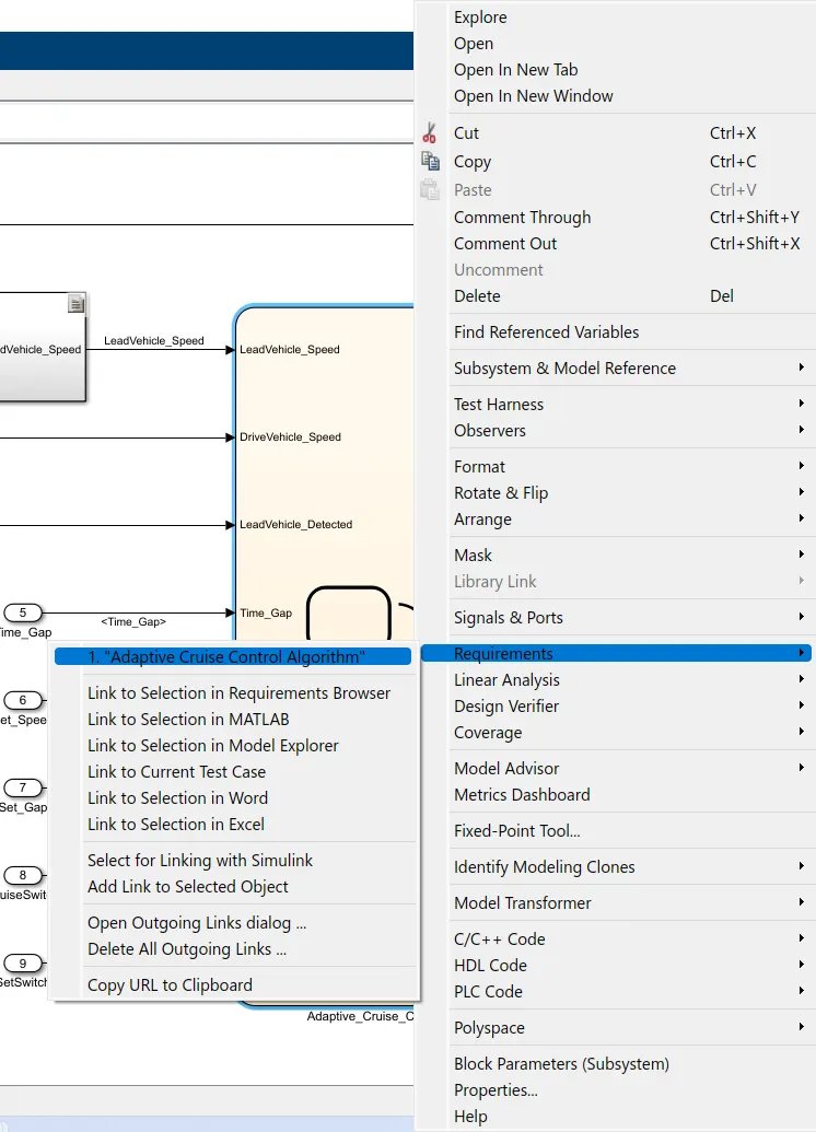
Requirement Tagging: attached and named ProACC.slmx, Requirement Document - Copy.docx
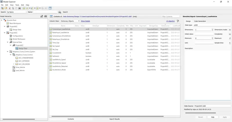
Creation of SLDD: files attached and named ProjectACC.sldd
Inputs, outputs, and Calibration parameters data are fed to SLDD
Signal Resolution:
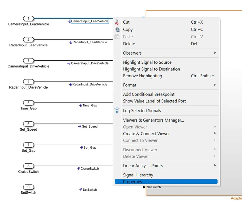
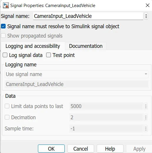
Data from SLDD will pass to the Simulink model block when the signal of the input and output is resolved or else the Simulink model will take junk files.
Right-click on the signal line and select properties. A new window will open Set the name and check resolve to Simulink object.
Press Ctrl + D to check the static error.
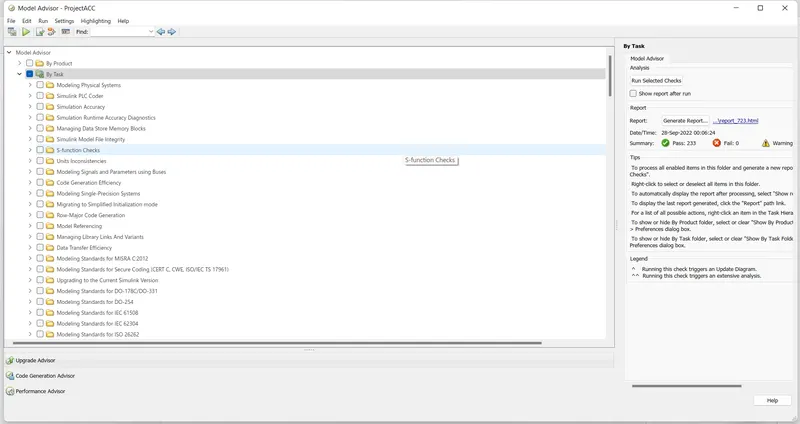
Model advisor: report attached and named reportMA.pdf
Configuration Parameters settings:
Code Generation:
ert_main.c
/*
 * File: ert_main.c
 *
 * Code generated for Simulink model 'ProjectACC'.
 *
 * Model version                  : 1.53
 * Simulink Coder version         : 9.5 (R2021a) 14-Nov-2020
 * C/C++ source code generated on : Tue Sep 27 20:09:56 2022
 *
 * Target selection: ert.tlc
 * Embedded hardware selection: Intel->x86-64 (Windows64)
 * Code generation objectives: Unspecified
 * Validation result: Not run
 */

#include
#include               /* This ert_main.c example uses printf/fflush */
#include "ProjectACC.h"                /* Model's header file */
#include "rtwtypes.h"

/*
 * Associating rt_OneStep with a real-time clock or interrupt service routine
 * is what makes the generated code "real-time".  The function rt_OneStep is
 * always associated with the base rate of the model.  Subrates are managed
 * by the base rate from inside the generated code.  Enabling/disabling
 * interrupts and floating point context switches are target specific.  This
 * example code indicates where these should take place relative to executing
 * the generated code step function.  Overrun behavior should be tailored to
 * your application needs.  This example simply sets an error status in the
 * real-time model and returns from rt_OneStep.
 */
void rt_OneStep(void);
void rt_OneStep(void)
{
  static boolean_T OverrunFlag = false;

  /* Disable interrupts here */

  /* Check for overrun */
  if (OverrunFlag) {
    rtmSetErrorStatus(ProjectACC_M, "Overrun");
    return;
  }

  OverrunFlag = true;

  /* Save FPU context here (if necessary) */
  /* Re-enable timer or interrupt here */
  /* Set model inputs here */

  /* Step the model */
  ProjectACC_step();

  /* Get model outputs here */

  /* Indicate task complete */
  OverrunFlag = false;

  /* Disable interrupts here */
  /* Restore FPU context here (if necessary) */
  /* Enable interrupts here */
}

/*
 * The example "main" function illustrates what is required by your
 * application code to initialize, execute, and terminate the generated code.
 * Attaching rt_OneStep to a real-time clock is target specific.  This example
 * illustrates how you do this relative to initializing the model.
 */
int_T main(int_T argc, const char *argv[])
{
  /* Unused arguments */
  (void)(argc);
  (void)(argv);

  /* Initialize model */
  ProjectACC_initialize();

  /* Attach rt_OneStep to a timer or interrupt service routine with
   * period 0.01 seconds (the model's base sample time) here.  The
   * call syntax for rt_OneStep is
   *
   *  rt_OneStep();
   */
  printf("Warning: The simulation will run forever. "
         "Generated ERT main won't simulate model step behavior. "
         "To change this behavior select the 'MAT-file logging' option.n");
  fflush((NULL));
  while (rtmGetErrorStatus(ProjectACC_M) == (NULL)) {
    /*  Perform other application tasks here */
  }

  /* Disable rt_OneStep() here */

  /* Terminate model */
  ProjectACC_terminate();
  return 0;
}

/*
 * File trailer for generated code.
 *
 * [EOF]
 */
ProjectACC.c
/*
 * File: ProjectACC.c
 *
 * Code generated for Simulink model 'ProjectACC'.
 *
 * Model version                  : 1.53
 * Simulink Coder version         : 9.5 (R2021a) 14-Nov-2020
 * C/C++ source code generated on : Tue Sep 27 20:09:56 2022
 *
 * Target selection: ert.tlc
 * Embedded hardware selection: Intel->x86-64 (Windows64)
 * Code generation objectives: Unspecified
 * Validation result: Not run
 */

#include "ProjectACC.h"
#include "ProjectACC_private.h"

/* Named constants for Chart: '/Adaptive_Cruise_Control' */
#define IN_LeadVehicle_Detected_Follow ((uint8_T)1U)
#define IN_LeadVehicle_Detected_Resume ((uint8_T)2U)
#define IN_LeadVehicle_Not_Detected_Res ((uint8_T)4U)
#define IN_LeadVehicle_Speed_Lessthan_S ((uint8_T)5U)
#define IN_LeadVehicle_Speed_equal_Set_ ((uint8_T)6U)
#define Pro_IN_LeadVehicle_Not_Detected ((uint8_T)3U)
#define ProjectACC_IN_ACC_OFFMODE      ((uint8_T)1U)
#define ProjectACC_IN_ACC_ON_MODE      ((uint8_T)2U)
#define ProjectACC_IN_ACC_STANDBYMODE  ((uint8_T)3U)
#define ProjectACC_IN_NO_ACTIVE_CHILD  ((uint8_T)0U)

/* Block states (default storage) */
DW_ProjectACC_T ProjectACC_DW;

/* Real-time model */
static RT_MODEL_ProjectACC_T ProjectACC_M_;
RT_MODEL_ProjectACC_T *const ProjectACC_M = &ProjectACC_M_;
real_T rt_roundd_snf(real_T u)
{
  real_T y;
  if (fabs(u) < 4.503599627370496E+15) {
    if (u >= 0.5) {
      y = floor(u + 0.5);
    } else if (u > -0.5) {
      y = u * 0.0;
    } else {
      y = ceil(u - 0.5);
    }
  } else {
    y = u;
  }

  return y;
}

/* Model step function */
void ProjectACC_step(void)
{
  int32_T tmp;
  int32_T tmp_0;
  uint8_T rtb_Add;
  uint8_T rtb_DriveVehicle_Speed;
  uint8_T tmp_1;
  uint8_T tmp_2;

  /* Sum: '/Add' incorporates:
   *  Inport: '/CameraInput_LeadVehicle'
   *  Inport: '/RadarInput_LeadVehicle'
   */
  rtb_Add = (uint8_T)((uint32_T)CameraInput_LeadVehicle + RadarInput_LeadVehicle);

  /* Sum: '/Add' incorporates:
   *  Delay: '/Delay'
   *  Inport: '/CameraInput_DriveVehicle'
   *  Inport: '/RadarInput_DriveVehicle'
   */
  rtb_DriveVehicle_Speed = (uint8_T)((uint32_T)(uint8_T)((uint32_T)
    Acceleration_Mode + CameraInput_DriveVehicle) + RadarInput_DriveVehicle);

  /* Chart: '/Adaptive_Cruise_Control' incorporates:
   *  Inport: '/CruiseSwitch'
   *  Inport: '/RadarInput_DriveVehicle'
   *  Inport: '/SetSwitch'
   *  Inport: '/Set_Gap'
   *  Inport: '/Set_Speed'
   *  Inport: '/Time_Gap'
   */
  if (ProjectACC_DW.is_active_c3_ProjectACC == 0U) {
    ProjectACC_DW.is_active_c3_ProjectACC = 1U;
    ProjectACC_DW.is_c3_ProjectACC = ProjectACC_IN_ACC_OFFMODE;
    Acceleration_Mode = 0U;
  } else {
    switch (ProjectACC_DW.is_c3_ProjectACC) {
     case ProjectACC_IN_ACC_OFFMODE:
      if (CruiseSwitch) {
        ProjectACC_DW.is_c3_ProjectACC = ProjectACC_IN_ACC_STANDBYMODE;
        Acceleration_Mode = 1U;
      }
      break;

     case ProjectACC_IN_ACC_ON_MODE:
      if (!CruiseSwitch) {
        ProjectACC_DW.is_ACC_ON_MODE = ProjectACC_IN_NO_ACTIVE_CHILD;
        ProjectACC_DW.is_c3_ProjectACC = ProjectACC_IN_ACC_OFFMODE;
        Acceleration_Mode = 0U;
      } else if (!SetSwitch) {
        ProjectACC_DW.is_ACC_ON_MODE = ProjectACC_IN_NO_ACTIVE_CHILD;
        ProjectACC_DW.is_c3_ProjectACC = ProjectACC_IN_ACC_STANDBYMODE;
        Acceleration_Mode = 1U;
      } else {
        switch (ProjectACC_DW.is_ACC_ON_MODE) {
         case IN_LeadVehicle_Detected_Follow:
          if (RadarInput_DriveVehicle == 0) {
            ProjectACC_DW.is_ACC_ON_MODE = Pro_IN_LeadVehicle_Not_Detected;
            Acceleration_Mode = 1U;
          } else if (((RadarInput_DriveVehicle == 1) && (rtb_Add < Set_Speed)) ||
                     (Time_Gap < Set_Gap)) {
            ProjectACC_DW.is_ACC_ON_MODE = IN_LeadVehicle_Speed_Lessthan_S;
            Acceleration_Mode = 4U;
          }
          break;

         case IN_LeadVehicle_Detected_Resume:
          if ((rtb_DriveVehicle_Speed == Set_Speed) && (rtb_Add >= Set_Speed) &&
              (Time_Gap >= Set_Gap)) {
            ProjectACC_DW.is_ACC_ON_MODE = IN_LeadVehicle_Detected_Follow;
            Acceleration_Mode = 2U;
          } else if (RadarInput_DriveVehicle == 0) {
            ProjectACC_DW.is_ACC_ON_MODE = IN_LeadVehicle_Not_Detected_Res;
            Acceleration_Mode = 1U;
          } else if ((rtb_DriveVehicle_Speed < Set_Speed) && (rtb_Add >
                      rtb_DriveVehicle_Speed) && (Time_Gap >= Set_Gap)) {
            ProjectACC_DW.is_ACC_ON_MODE = IN_LeadVehicle_Speed_equal_Set_;
            Acceleration_Mode = 5U;
          }
          break;

         case Pro_IN_LeadVehicle_Not_Detected:
          if (((RadarInput_DriveVehicle == 1) && (rtb_Add < Set_Speed)) ||
              (Time_Gap < Set_Gap)) {
            ProjectACC_DW.is_ACC_ON_MODE = IN_LeadVehicle_Speed_Lessthan_S;
            Acceleration_Mode = 4U;
          } else if ((RadarInput_DriveVehicle == 1) && (rtb_DriveVehicle_Speed ==
                      Set_Speed) && (rtb_Add >= Set_Speed) && (Time_Gap >=
                      Set_Gap)) {
            ProjectACC_DW.is_ACC_ON_MODE = IN_LeadVehicle_Detected_Follow;
            Acceleration_Mode = 2U;
          }
          break;

         case IN_LeadVehicle_Not_Detected_Res:
          break;

         case IN_LeadVehicle_Speed_Lessthan_S:
          if ((RadarInput_DriveVehicle == 0) && (rtb_DriveVehicle_Speed ==
               Set_Speed)) {
            ProjectACC_DW.is_ACC_ON_MODE = Pro_IN_LeadVehicle_Not_Detected;
            Acceleration_Mode = 1U;
          } else {
            tmp = (int32_T)rt_roundd_snf((real_T)rtb_Add * 1.25);
            tmp_0 = (int32_T)rt_roundd_snf(1.25 * (real_T)Set_Gap);
            if (tmp < 256) {
              tmp_1 = (uint8_T)tmp;
            } else {
              tmp_1 = MAX_uint8_T;
            }

            if (tmp_0 < 256) {
              tmp_2 = (uint8_T)tmp_0;
            } else {
              tmp_2 = MAX_uint8_T;
            }

            tmp = (int32_T)rt_roundd_snf(0.75 * (real_T)Set_Gap);
            if (((tmp_1 >= rtb_DriveVehicle_Speed) && ((int32_T)rt_roundd_snf
                  ((real_T)rtb_Add * 0.75) <= rtb_DriveVehicle_Speed) &&
                 (rtb_DriveVehicle_Speed < Set_Speed) && (Time_Gap <= tmp_2) &&
                 (Time_Gap >= tmp)) || (((rtb_Add < Set_Speed) && (rtb_Add <
                   rtb_DriveVehicle_Speed)) || (tmp == Time_Gap))) {
              ProjectACC_DW.is_ACC_ON_MODE = IN_LeadVehicle_Speed_equal_Set_;
              Acceleration_Mode = 5U;
            }
          }
          break;

         default:
          /* case IN_LeadVehicle_Speed_equal_Set_Speed: */
          if ((RadarInput_DriveVehicle == 0) || (rtb_DriveVehicle_Speed <=
               Set_Speed)) {
            ProjectACC_DW.is_ACC_ON_MODE = IN_LeadVehicle_Not_Detected_Res;
            Acceleration_Mode = 1U;
          } else if (((rtb_DriveVehicle_Speed < Set_Speed) && (rtb_Add >
                       rtb_DriveVehicle_Speed)) || (Time_Gap >= Set_Gap)) {
            ProjectACC_DW.is_ACC_ON_MODE = IN_LeadVehicle_Detected_Resume;
            Acceleration_Mode = 3U;
          }
          break;
        }
      }
      break;

     default:
      /* case IN_ACC_STANDBYMODE: */
      if (!CruiseSwitch) {
        ProjectACC_DW.is_c3_ProjectACC = ProjectACC_IN_ACC_OFFMODE;
        Acceleration_Mode = 0U;
      } else if (SetSwitch) {
        ProjectACC_DW.is_c3_ProjectACC = ProjectACC_IN_ACC_ON_MODE;
        ProjectACC_DW.is_ACC_ON_MODE = IN_LeadVehicle_Detected_Follow;
        Acceleration_Mode = 2U;
      }
      break;
    }
  }

  /* End of Chart: '/Adaptive_Cruise_Control' */
}

/* Model initialize function */
void ProjectACC_initialize(void)
{
  /* (no initialization code required) */
}

/* Model terminate function */
void ProjectACC_terminate(void)
{
  /* (no terminate code required) */
}

/*
 * File trailer for generated code.
 *
 * [EOF]
 */
ProjectACC.h
/*
 * File: ProjectACC.h
 *
 * Code generated for Simulink model 'ProjectACC'.
 *
 * Model version                  : 1.53
 * Simulink Coder version         : 9.5 (R2021a) 14-Nov-2020
 * C/C++ source code generated on : Tue Sep 27 20:09:56 2022
 *
 * Target selection: ert.tlc
 * Embedded hardware selection: Intel->x86-64 (Windows64)
 * Code generation objectives: Unspecified
 * Validation result: Not run
 */

#ifndef RTW_HEADER_ProjectACC_h_
#define RTW_HEADER_ProjectACC_h_
#include
#ifndef ProjectACC_COMMON_INCLUDES_
#define ProjectACC_COMMON_INCLUDES_
#include "rtwtypes.h"
#endif                                 /* ProjectACC_COMMON_INCLUDES_ */

#include "ProjectACC_types.h"

/* Includes for objects with custom storage classes. */
#include "Adaptive_Cruise_Control_Function.h"

/* Macros for accessing real-time model data structure */
#ifndef rtmGetErrorStatus
#define rtmGetErrorStatus(rtm)         ((rtm)->errorStatus)
#endif

#ifndef rtmSetErrorStatus
#define rtmSetErrorStatus(rtm, val)    ((rtm)->errorStatus = (val))
#endif

/* Block states (default storage) for system '' */
typedef struct {
  uint8_T is_active_c3_ProjectACC;     /* '/Adaptive_Cruise_Control' */
  uint8_T is_c3_ProjectACC;            /* '/Adaptive_Cruise_Control' */
  uint8_T is_ACC_ON_MODE;              /* '/Adaptive_Cruise_Control' */
} DW_ProjectACC_T;

/* Real-time Model Data Structure */
struct tag_RTM_ProjectACC_T {
  const char_T * volatile errorStatus;
};

/* Block states (default storage) */
extern DW_ProjectACC_T ProjectACC_DW;

/* Model entry point functions */
extern void ProjectACC_initialize(void);
extern void ProjectACC_step(void);
extern void ProjectACC_terminate(void);

/* Real-time Model object */
extern RT_MODEL_ProjectACC_T *const ProjectACC_M;

/*-
 * These blocks were eliminated from the model due to optimizations:
 *
 * Block '/Signal Conversion' : Eliminate redundant signal conversion block
 */

/*-
 * The generated code includes comments that allow you to trace directly
 * back to the appropriate location in the model.  The basic format
 * is /block_name, where system is the system number (uniquely
 * assigned by Simulink) and block_name is the name of the block.
 *
 * Use the MATLAB hilite_system command to trace the generated code back
 * to the model.  For example,
 *
 * hilite_system('')    - opens system 3
 * hilite_system('/Kp') - opens and selects block Kp which resides in S3
 *
 * Here is the system hierarchy for this model
 *
 * '' : 'ProjectACC'
 * ''   : 'ProjectACC/Adaptive_Cruise_Control_System'
 * ''   : 'ProjectACC/Adaptive_Cruise_Control_System/Adaptive_Cruise_Control'
 * ''   : 'ProjectACC/Adaptive_Cruise_Control_System/Drive_Vehicle'
 * ''   : 'ProjectACC/Adaptive_Cruise_Control_System/Lead_Vehicle'
 */
#endif                                 /* RTW_HEADER_ProjectACC_h_ */

/*
 * File trailer for generated code.
 *
 * [EOF]
 */
ProjectACC_private.h
/*
 * File: ProjectACC_private.h
 *
 * Code generated for Simulink model 'ProjectACC'.
 *
 * Model version                  : 1.53
 * Simulink Coder version         : 9.5 (R2021a) 14-Nov-2020
 * C/C++ source code generated on : Tue Sep 27 20:09:56 2022
 *
 * Target selection: ert.tlc
 * Embedded hardware selection: Intel->x86-64 (Windows64)
 * Code generation objectives: Unspecified
 * Validation result: Not run
 */

#ifndef RTW_HEADER_ProjectACC_private_h_
#define RTW_HEADER_ProjectACC_private_h_
#include "rtwtypes.h"

/* Imported (extern) block signals */
extern uint8_T CameraInput_LeadVehicle;/* '/CameraInput_LeadVehicle' */
extern uint8_T RadarInput_LeadVehicle; /* '/RadarInput_LeadVehicle' */
extern uint8_T CameraInput_DriveVehicle;/* '/CameraInput_DriveVehicle' */
extern uint8_T RadarInput_DriveVehicle;/* '/RadarInput_DriveVehicle' */
extern uint8_T Time_Gap;               /* '/Time_Gap' */
extern uint8_T Set_Speed;              /* '/Set_Speed' */
extern uint8_T Set_Gap;                /* '/Set_Gap' */
extern boolean_T CruiseSwitch;         /* '/CruiseSwitch' */
extern boolean_T SetSwitch;            /* '/SetSwitch' */
extern real_T rt_roundd_snf(real_T u);

#endif                                 /* RTW_HEADER_ProjectACC_private_h_ */

/*
 * File trailer for generated code.
 *
 * [EOF]
 */
ProjectACC_types.h
/*
 * File: ProjectACC_types.h
 *
 * Code generated for Simulink model 'ProjectACC'.
 *
 * Model version                  : 1.53
 * Simulink Coder version         : 9.5 (R2021a) 14-Nov-2020
 * C/C++ source code generated on : Tue Sep 27 20:09:56 2022
 *
 * Target selection: ert.tlc
 * Embedded hardware selection: Intel->x86-64 (Windows64)
 * Code generation objectives: Unspecified
 * Validation result: Not run
 */

#ifndef RTW_HEADER_ProjectACC_types_h_
#define RTW_HEADER_ProjectACC_types_h_

/* Model Code Variants */

/* Forward declaration for rtModel */
typedef struct tag_RTM_ProjectACC_T RT_MODEL_ProjectACC_T;

#endif                                 /* RTW_HEADER_ProjectACC_types_h_ */

/*
 * File trailer for generated code.
 *
 * [EOF]
 */
Adaptive_Cruise_Control_Function.h
/*
 * File: Adaptive_Cruise_Control_Function.h
 *
 * Code generated for Simulink model 'ProjectACC'.
 *
 * Model version                  : 1.53
 * Simulink Coder version         : 9.5 (R2021a) 14-Nov-2020
 * C/C++ source code generated on : Tue Sep 27 20:09:56 2022
 *
 * Target selection: ert.tlc
 * Embedded hardware selection: Intel->x86-64 (Windows64)
 * Code generation objectives: Unspecified
 * Validation result: Not run
 */

#ifndef RTW_HEADER_Adaptive_Cruise_Control_Function_h_
#define RTW_HEADER_Adaptive_Cruise_Control_Function_h_
#include "rtwtypes.h"
#include "ProjectACC_types.h"

/* Exported data declaration */

/* Declaration for custom storage class: ExportToFile */
extern uint8_T Acceleration_Mode;      /* '/Adaptive_Cruise_Control' */

#endif                      /* RTW_HEADER_Adaptive_Cruise_Control_Function_h_ */

/*
 * File trailer for generated code.
 *
 * [EOF]
 */
Adaptive_Cruise_Control_Function_ROM.c
/*
 * File: Adaptive_Cruise_Control_Function_ROM.c
 *
 * Code generated for Simulink model 'ProjectACC'.
 *
 * Model version                  : 1.53
 * Simulink Coder version         : 9.5 (R2021a) 14-Nov-2020
 * C/C++ source code generated on : Tue Sep 27 20:09:56 2022
 *
 * Target selection: ert.tlc
 * Embedded hardware selection: Intel->x86-64 (Windows64)
 * Code generation objectives: Unspecified
 * Validation result: Not run
 */

#include "rtwtypes.h"
#include "ProjectACC_types.h"

/* Exported data definition */

/* Definition for custom storage class: ExportToFile */
uint8_T Acceleration_Mode;             /* '/Adaptive_Cruise_Control' */

/*
 * File trailer for generated code.
 *
 * [EOF]
 */
Conclusion:
MBD-related processes: Requirement Tagging & Traceability, SLDD creation, Configuration Parameter changes, Model Advisor check & Code Generation are Performed.