Project 2 Adaptive Cruise Control
Project 2(Adaptive Cruise Control)
Objectives:
To Develop Adaptive Cruise Control feature as per the requirement document using MATLAB Simulink.
Model configuration setting parameters:
- Follow all the MBD related processes: Requirement Tagging & Traceability, SLDD creation, Configuration Parameter changes, Model Advisor check & Code Generation.
- In Configuration Parameters: enable “Support Floating Numbers” under Code Generation settings.
- Use Embedded Coder to generate the code.
- If choosing code generation, Storage class for Input signals: ImportedExtern; Storage class for Output signal: Export to File; Storage class for local signals: localizable; Storage class for calibration signals: Const.
- Choose sample time for all signals as 0.01s
Requirements:
Requirement 1– Lead Vehicle:
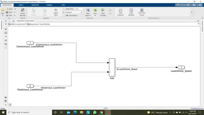
- Lead Vehicle is a vehicle which is driving in the road ahead of our drive vehicle. Two input signals (Signal Name: CameraInput_LeadVehicle & RadarInput_LeadVehicle).
- Ideally sensor fusion techniques will be deployed to process & analyze data from camera & radar. For complexity reasons, let’s not adapt to any such algorithms.
- We can simply add both the radar & camera inputs & the corresponding output is read as Speed profile output (Signal Name: LeadVehicle_Speed).
- Speed data of the lead vehicle is critical in implementing the Adaptive Cruise Control algorithm.
Requirement 2 – Drive Vehicle:
- Drive Vehicle is the vehicle driven by the user & this is the vehicle which has ACC algorithm in it.
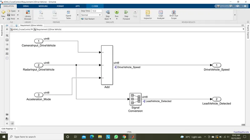
- Like the Lead Vehicle, Drive Vehicle algorithm also has 2 input signals (Signal Name: CameraInput_DriveVehicle, RadarInput_DriveVehicle) & one signal coming as an Input to this subsystem (Signal Name: Acceleration_Mode) – three inputs into this requirement in total.
- Like the above requirement, sensor fusion techniques will also be deployed here, for complexity reasons we are ignoring them.
- Two output signals come from this subsystem (Signal Name: DriveVehicle_Speed & LeadVehicle_Detected).
- Signal DriveVehicle_Speed is summation of three input signals mentioned above & LeadVehicle_Detected is renamed from Input Signal RadarInput_DriveVehicle by mere use of Signal Conversion block.
Requirement 3 – Adaptive Cruise Control Algorithm:
- Adaptive Cruise Control feature has 3 major modes of operation: OFF Mode, STANDBY Mode & ON Mode. This particular requirement has to be implemented as state machine logic in Simulink.
- The input signals to this state machine system are (Signal Name: Time_Gap, Set_Speed, Set_Gap, CruiseSwitch, SetSwitch).
- Also, the output signals (Signal Name: DriveVehicle_Speed & LeadVehicle_Detected) from requirement-2 is fed back as an input signal into this state machine block.
- Additionally, output signal (Signal Name: LeadVehicle_Speed) from requirement-1 is given as an input signal to this state machine block as well.
- Output from this subsystem is a signal (Signal Name: Acceleration_Mode) which governs the vehicular speed of the drive vehicle which automatically adjusts its speed & velocity to match the lead vehicle.
Requirement 3a – ACC OFF MODE state logic:
- This is the default state inside state machine logic. Output signal Acceleration_Mode is at value 0 in this state.
- This state is governed by input signal CruiseSwitch.
- If CruiseSwitch is equal to 1, state ACC STANDBY mode will get activated. If CruiseSwitch is equal to 0, state ACC OFF mode will get activated, from either ACC ON mode or ACC STANDBY mode
Requirement 3b – ACC STANDBY MODE state logic:
- This is the second activated state inside state machine logic. Output signal Acceleration_Mode is at value 1 in this state.
- This state is governed by both input signals CruiseSwitch & SetSwitch.
- If CruiseSwitch is equal to 1, state ACC STANDBY mode will get activated. If CruiseSwitch is equal to 0, state ACC OFF mode will get activated, from either ACC ON mode or ACC STANDBY mode
- If SetSwitch is equal to 1, state ACC ON mode will get activated. If SetSwitch is equal to 0, state ACC STANDBY mode will get activated.
Requirement 3c – ACC ON MODE state logic:
This state will be activated when input signal SetSwitch is equal to 1. There are 6 sub states to this state logic: They are:
- LeadVehicle_Detected_Follow (Default)
- LeadVehicle_Not_Detected
- LeadVehicle_Detected_Resume
- LeadVehicle_Not_Detected_Resume
- LeadVehicle_Speed_lessthan_Set_Speed
Requirement 3c (i) – LeadVehicle_Detected_Follow (ACC ON MODE):
- This is the default sub state inside ACC ON MODE state. Output signal Acceleration_Mode is equal to 2.
- Condition to transit from LeadVehicle_Detected_Follow to LeadVehicle_Not_Detected; Input signal condition LeadVehicle_Detected == 0.
- Condition to transit from LeadVehicle_Detected_Follow to LeadVehicle_Speed_lessthan_Set_Speed; Input Signals condition (LeadVehicle_Detected == 1) && (LeadVehicle_Speed < Set_Speed) || (Time_Gap < Set_Gap).
Requirement 3c (ii) – LeadVehicle_Not_Detected (ACC ON MODE):
- Output signal Acceleration_Mode is equal to 1.
- Condition to transit from LeadVehicle_Not_Detected to LeadVehicle_Detected_Follow; Input signals condition [(LeadVehicle_Detected==1) && (DriveVehicle_Speed == Set_Speed) && (LeadVehicle_Speed >= Set_Speed) && (Time_Gap >= Set_Gap)]
- Condition to transit from LeadVehicle_Not_Detected to LeadVehicle_Speed_lessthan_Set_Speed; Input signals condition [(LeadVehicle_Detected == 1) && (LeadVehicle_Speed < Set_Speed) || (Time_Gap < Set_Gap)]
Requirement 3c (iii) – LeadVehicle_Detected_Resume (ACC ON MODE):
- Output signal Acceleration_Mode is equal to 3.
- Condition to transit from LeadVehicle_Detected_Resume to LeadVehicle_Detected_Follow; Input signals condition [(DriveVehicle_Speed == Set_Speed) && (LeadVehicle_Speed >= Set_Speed) && (Time_Gap >= Set_Gap)]
- Condition to transit from LeadVehicle_Detected_Resume to LeadVehicle_Not_Detected_Resume; Input signal condition LeadVehicle_Detected==0.
- Condition to transit from LeadVehicle_Detected_Resume to LeadVehicle_Speed_equal_Set_Speed; Input Signal condition [(DriveVehicle_Speed < Set_Speed) && (LeadVehicle_Speed > DriveVehicle_Speed) && (Time_Gap >= Set_Gap)]
Requirement 3c (iv) - LeadVehicle_Not_Detected_Resume (ACC ON MODE):
- Output signal Acceleration_Mode is equal to 1.
Requirement 3c (v) - LeadVehicle_Speed_lessthan_Set_Speed (ACC ON MODE):
- Output signal Acceleration_Mode is equal to 4.
- Condition to transit from LeadVehicle_Speed_lessthan_Set_Speed to LeadVehicle_Not_Detected; Input signal condition [(LeadVehicle_Detected == 0) && (DriveVehicle_Speed == Set_Speed)]
- Condition to transit from LeadVehicle_Speed_lessthan_Set_Speed to LeadVehicle_Speed_equal_Set_Speed; Input signals condition [((LeadVehicle_Speed*1.25>=DriveVehicle_Speed) && (LeadVehicle_Speed * 0.75<=DriveVehicle_Speed)) && (DriveVehicle_Speed < Set_Speed) && ((Time_Gap<=1.25*Set_Gap) && (Time_Gap >=0.75*Set_Gap))]
Requirement 3c (vi) - LeadVehicle_Speed_equal_Set_Speed (ACC ON MODE):
- Output signal Acceleration_Mode is equal to 5.
- Condition to transit from LeadVehicle_Speed_equal_Set_Speed to LeadVehicle_Not_Detected_Resume; Input signal conditions is [(LeadVehicle_Detected == 0) || (DriveVehicle_Speed <= Set_Speed)]
- Condition to transit from LeadVehicle_Speed_equal_Set_Speed to LeadVehicle_Detected_Resume; Input signal conditions [(DriveVehicle_Speed < Set_Speed) && (LeadVehicle_Speed > DriveVehicle_Speed) || (Time_Gap >= Set_Gap)]
- Condition to transit from LeadVehicle_Speed_equal_Set_Speed to LeadVehicle_Speed_lessthan_Set_Speed; Input signals conditions [(LeadVehicle_Speed
SLDD Requirements:
|
Signal / Calibration Name |
Signal Type |
Data Type |
Dimension |
Min |
Max |
Initial Value |
Units |
|
CameraInput_LeadVehicle |
Input |
Uint8 |
1 |
0 |
255 |
- |
- |
|
RadarInput_LeadVehicle |
Input |
Uint8 |
1 |
0 |
255 |
- |
- |
|
CameraInput_DriveVehicle |
Input |
Uint8 |
1 |
0 |
255 |
- |
- |
|
RadarInput_DriveVehicle |
Input |
Uint8 |
1 |
0 |
255 |
- |
- |
|
Time_Gap |
Input |
Uint8 |
1 |
0 |
255 |
- |
- |
|
Set_Speed |
Input |
Uint8 |
1 |
0 |
255 |
- |
- |
|
Set_Gap |
Input |
Uint8 |
1 |
0 |
255 |
- |
- |
|
CruiseSwitch |
Input |
Boolean |
1 |
0 |
1 |
- |
- |
|
SetSwitch |
Input |
Boolean |
1 |
0 |
1 |
- |
- |
|
Acceleration_Mode |
Output |
Uint8 |
1 |
0 |
255 |
- |
- |
|
LeadVehicle_Speed |
Output |
Uint8 |
1 |
0 |
255 |
- |
- |
|
DriveVehicle_Speed |
Output |
Uint8 |
1 |
0 |
255 |
- |
- |
|
LeadVehicle_Detected |
Output |
Uint8 |
1 |
0 |
255 |
- |
- |
Overall Model:
As per the requirements we had created a simulink model for adaptive cruise control feature.
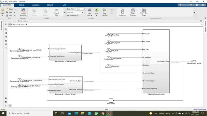
Here consist of three requirement subsystems,
Requirement 1:Lead vehicle subsystem.
Requirement 2:Drive vehicle subsystem.
Requirement 3:Adaptive Cruise Control subsystem.
Requirement 1:
As to find out the lead vehicle speed is quite complicated,for simplicity as per the requirement 1, the input from CameraInput_LeadVehicle signal and RadarInput_LeadVehicle signal are summed up to get the LeadVehicle_Speed output.
Requirement 2:
For DriveVehicle_Speed calculation we are adding CameraInput_DriveVehicle,RadarInput_DriveVehicle and Acceleration_Mode feedback from Cruise control algorithm.
The outputs from this subsystem as DriveVehicle_Speed and Lead_Vehicle_Detected by propagating RadarInput_DriveVehicle in to signal conversion block.
Requirement 3:
In this subsystem we are using a state flow logics to implement the requirements 3a,3b,3c,3c(i),3c(ii),3c(iii),3c(iv),3c(v),3c(vi).
The inputs for the state flow are,
- Time_Gap.
- Set_Speed.
- Set_Gap.
- CruiseSwitch.
- SetSwitch.
- DriveVehicle_Speed from Requirement 2 subsystem.
- LeadVehicle_Speed from Requirement 1 subsystem.
- LeadVehicle_Detected from Requirement 2 subsystem.
The output from this subsystem is,
- Acceleration_Mode-Based on the LeadVehicle_Speed the Acceleration_Mode udjust its controlling accaleration given output to maintain constant speed.
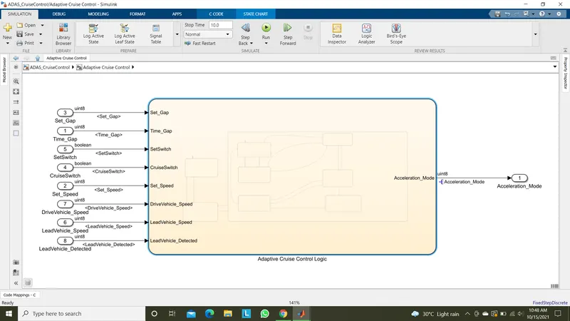
State flow logic(Adaptive Cruise Control Logic):
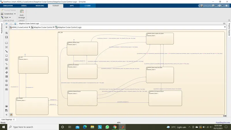
In this logic we had created three modes of operation as,
- ACC_OFF mode.
- ACC_STANDBY mode.
- ACC_ON mode.
In ACC_ON mode we have further 6 modes of operations as,
- LeadVehicle_Detected_Follow (Default).
- LeadVehicle_Not_Detected.
- LeadVehicle_Detected_Resume.
- LeadVehicle_Not_Detected_Resume.
- LeadVehicle_Speed_lessthan_Set_Speed.
- LeadVehicle_Speed_equal_Set_Speed.
All these modes of operations are modelled as per the given as mentioned in requirements section.
SLDD file creation:
For all the input and output signals resolved and propagated in this model are declared in the SLDD file created as shown below,
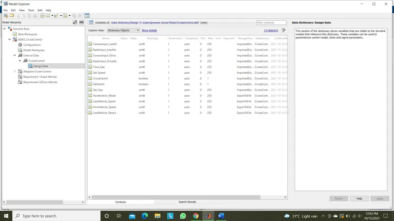
The signal parameters are declares as per the SLDD datatype requirements mention earlier.
The code generated from output signals are stored in ADAS_CruiseControl.h and ADAS_CruiseControl.c files.
Results:
After compiling the model we are getting nil errors on model creation justifies our logic on modelling for requirements are correct.
Model advisor check:
For the model advisor check of MAB guidelines we are getting the report as shown below,
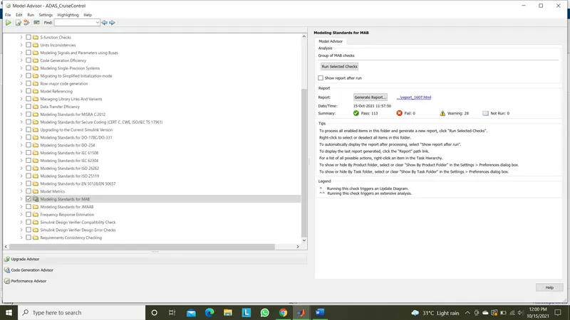
The report for model advisor check attached with this project submission.
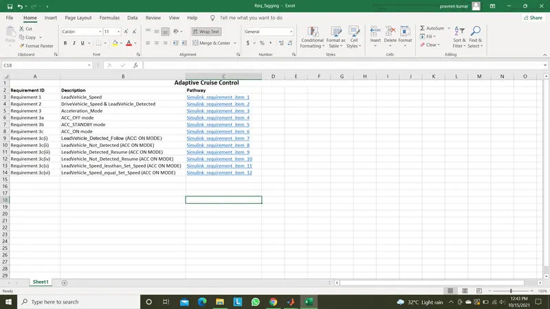
Requirement tagging:
Code generation:
1	/*
2	 * File: ADAS_CruiseControl.c
3	 *
4	 * Code generated for Simulink model 'ADAS_CruiseControl'.
5	 *
6	 * Model version                  : 1.80
7	 * Simulink Coder version         : 9.4 (R2020b) 29-Jul-2020
8	 * C/C++ source code generated on : Fri Oct 15 10:29:13 2021
9	 *
10	 * Target selection: ert.tlc
11	 * Embedded hardware selection: Intel->x86-64 (Windows64)
12	 * Code generation objectives: Unspecified
13	 * Validation result: Not run
14	 */
15
16	#include "ADAS_CruiseControl.h"
17	#include "ADAS_CruiseControl_private.h"
18
19	/* Named constants for Chart: '<S1>/CharAdaptive Cruise Control Logic' */
20	#define ADAS_CruiseC_IN_NO_ACTIVE_CHILD ((uint8_T)0U)
21	#define ADAS_CruiseContr_IN_ACC_STANDBY ((uint8_T)3U)
22	#define ADAS_CruiseControl_IN_ACC_OFF  ((uint8_T)1U)
23	#define ADAS_CruiseControl_IN_ACC_ON   ((uint8_T)2U)
24	#define ADA_IN_LeadVehicle_Not_Detected ((uint8_T)3U)
25	#define IN_LeadVehicle_Detected_Follow ((uint8_T)1U)
26	#define IN_LeadVehicle_Detected_Resume ((uint8_T)2U)
27	#define IN_LeadVehicle_Not_Detected_Res ((uint8_T)4U)
28	#define IN_LeadVehicle_Speed_Lessthan_S ((uint8_T)5U)
29	#define IN_LeadVehicle_Speed_equal_Set_ ((uint8_T)6U)
30
31	/* Exported data definition */
32
33	/* Definition for custom storage class: ExportToFile */
34	uint8_T Acceleration_Mode;        /* '<S1>/CharAdaptive Cruise Control Logic' */
35	uint8_T DriveVehicle_Speed;            /* '<S3>/Add' */
36	uint8_T LeadVehicle_Detected;          /* '<S3>/Signal Conversion' */
37	uint8_T LeadVehicle_Speed;             /* '<S2>/Add' */
38
39	/* Block states (default storage) */
40	DW_ADAS_CruiseControl_T ADAS_CruiseControl_DW;
41
42	/* Real-time model */
43	static RT_MODEL_ADAS_CruiseControl_T ADAS_CruiseControl_M_;
44	RT_MODEL_ADAS_CruiseControl_T *const ADAS_CruiseControl_M =
45	  &ADAS_CruiseControl_M_;
46	real_T rt_roundd_snf(real_T u)
47	{
48	  real_T y;
49	  if (fabs(u) < 4.503599627370496E+15) {
50	    if (u >= 0.5) {
51	      y = floor(u + 0.5);
52	    } else if (u > -0.5) {
53	      y = u * 0.0;
54	    } else {
55	      y = ceil(u - 0.5);
56	    }
57	  } else {
58	    y = u;
59	  }
60
61	  return y;
62	}
63
64	/* Model step function */
65	void ADAS_CruiseControl_step(void)
66	{
67	  int32_T tmp;
68	  int32_T tmp_0;
69	  uint8_T tmp_1;
70	  uint8_T tmp_2;
71
72	  /* Sum: '<S3>/Add' incorporates:
73	   *  Inport: '<Root>/CameraInput_DriveVehicle'
74	   *  Inport: '<Root>/RadarInput_DriveVehicle'
75	   *  UnitDelay: '<Root>/Unit Delay'
76	   */
77	  DriveVehicle_Speed = (uint8_T)((uint32_T)(uint8_T)((uint32_T)
78	    CameraInput_DriveVehicle + RadarInput_DriveVehicle) + Acceleration_Mode);
79
80	  /* Sum: '<S2>/Add' incorporates:
81	   *  Inport: '<Root>/CameraInput_LeadVehicle'
82	   *  Inport: '<Root>/RadarInput_LeadVehicle'
83	   */
84	  LeadVehicle_Speed = (uint8_T)((uint32_T)CameraInput_LeadVehicle +
85	    RadarInput_LeadVehicle);
86
87	  /* SignalConversion: '<S3>/Signal Conversion' incorporates:
88	   *  Inport: '<Root>/RadarInput_DriveVehicle'
89	   */
90	  LeadVehicle_Detected = RadarInput_DriveVehicle;
91
92	  /* Chart: '<S1>/CharAdaptive Cruise Control Logic' incorporates:
93	   *  Inport: '<Root>/CruiseSwitch'
94	   *  Inport: '<Root>/SetSwitch'
95	   *  Inport: '<Root>/Set_Gap'
96	   *  Inport: '<Root>/Set_Speed'
97	   *  Inport: '<Root>/Time_Gap'
98	   */
99	  if (ADAS_CruiseControl_DW.is_active_c3_ADAS_CruiseControl == 0U) {
100	    ADAS_CruiseControl_DW.is_active_c3_ADAS_CruiseControl = 1U;
101	    ADAS_CruiseControl_DW.is_c3_ADAS_CruiseControl =
102	      ADAS_CruiseControl_IN_ACC_OFF;
103	  } else {
104	    switch (ADAS_CruiseControl_DW.is_c3_ADAS_CruiseControl) {
105	     case ADAS_CruiseControl_IN_ACC_OFF:
106	      if (CruiseSwitch) {
107	        ADAS_CruiseControl_DW.is_c3_ADAS_CruiseControl =
108	          ADAS_CruiseContr_IN_ACC_STANDBY;
109	      }
110	      break;
111
112	     case ADAS_CruiseControl_IN_ACC_ON:
113	      if (!SetSwitch) {
114	        ADAS_CruiseControl_DW.is_ACC_ON = ADAS_CruiseC_IN_NO_ACTIVE_CHILD;
115	        ADAS_CruiseControl_DW.is_c3_ADAS_CruiseControl =
116	          ADAS_CruiseContr_IN_ACC_STANDBY;
117	      } else {
118	        switch (ADAS_CruiseControl_DW.is_ACC_ON) {
119	         case IN_LeadVehicle_Detected_Follow:
120	          if (LeadVehicle_Detected == 0) {
121	            ADAS_CruiseControl_DW.is_ACC_ON = ADA_IN_LeadVehicle_Not_Detected;
122	          } else {
123	            if (((LeadVehicle_Detected == 1) && (LeadVehicle_Speed < Set_Speed))
124	                || (Time_Gap < Set_Gap)) {
125	              ADAS_CruiseControl_DW.is_ACC_ON = IN_LeadVehicle_Speed_Lessthan_S;
126	              Acceleration_Mode = 4U;
127	            }
128	          }
129	          break;
130
131	         case IN_LeadVehicle_Detected_Resume:
132	          if ((DriveVehicle_Speed == Set_Speed) && (LeadVehicle_Speed >=
133	               Set_Speed) && (Time_Gap >= Set_Gap)) {
134	            ADAS_CruiseControl_DW.is_ACC_ON = IN_LeadVehicle_Detected_Follow;
135	          } else if (LeadVehicle_Detected == 0) {
136	            ADAS_CruiseControl_DW.is_ACC_ON = IN_LeadVehicle_Not_Detected_Res;
137	          } else {
138	            if ((DriveVehicle_Speed < Set_Speed) && (LeadVehicle_Speed >
139	                 DriveVehicle_Speed) && (Time_Gap >= Set_Gap)) {
140	              ADAS_CruiseControl_DW.is_ACC_ON = IN_LeadVehicle_Speed_equal_Set_;
141	            }
142	          }
143	          break;
144
145	         case ADA_IN_LeadVehicle_Not_Detected:
146	          if ((LeadVehicle_Detected == 1) && (DriveVehicle_Speed == Set_Speed) &&
147	              (LeadVehicle_Speed >= Set_Speed) && (Time_Gap >= Set_Gap)) {
148	            ADAS_CruiseControl_DW.is_ACC_ON = IN_LeadVehicle_Detected_Follow;
149	          } else {
150	            if (((LeadVehicle_Detected == 1) && (LeadVehicle_Speed < Set_Speed))
151	                || (Time_Gap < Set_Gap)) {
152	              ADAS_CruiseControl_DW.is_ACC_ON = IN_LeadVehicle_Speed_Lessthan_S;
153	              Acceleration_Mode = 4U;
154	            }
155	          }
156	          break;
157
158	         case IN_LeadVehicle_Not_Detected_Res:
159	          break;
160
161	         case IN_LeadVehicle_Speed_Lessthan_S:
162	          Acceleration_Mode = 4U;
163	          if ((LeadVehicle_Detected == 0) && (DriveVehicle_Speed == Set_Speed))
164	          {
165	            ADAS_CruiseControl_DW.is_ACC_ON = ADA_IN_LeadVehicle_Not_Detected;
166	          } else {
167	            tmp = (int32_T)rt_roundd_snf((real_T)LeadVehicle_Speed * 1.25);
168	            tmp_0 = (int32_T)rt_roundd_snf(1.25 * (real_T)Set_Gap);
169	            if (tmp < 256) {
170	              tmp_1 = (uint8_T)tmp;
171	            } else {
172	              tmp_1 = MAX_uint8_T;
173	            }
174
175	            if (tmp_0 < 256) {
176	              tmp_2 = (uint8_T)tmp_0;
177	            } else {
178	              tmp_2 = MAX_uint8_T;
179	            }
180
181	            if ((tmp_1 >= DriveVehicle_Speed) && ((int32_T)rt_roundd_snf((real_T)
182	                  LeadVehicle_Speed * 0.75) <= DriveVehicle_Speed) &&
183	                (DriveVehicle_Speed < Set_Speed) && (Time_Gap <= tmp_2) &&
184	                (Time_Gap >= (int32_T)rt_roundd_snf(0.75 * (real_T)Set_Gap))) {
185	              ADAS_CruiseControl_DW.is_ACC_ON = IN_LeadVehicle_Speed_equal_Set_;
186	            }
187	          }
188	          break;
189
190	         default:
191	          /* case IN_LeadVehicle_Speed_equal_Set_Speed: */
192	          if ((LeadVehicle_Detected == 0) || (DriveVehicle_Speed <= Set_Speed))
193	          {
194	            ADAS_CruiseControl_DW.is_ACC_ON = IN_LeadVehicle_Not_Detected_Res;
195	          } else if (((DriveVehicle_Speed < Set_Speed) && (LeadVehicle_Speed >
196	                       DriveVehicle_Speed)) || (Time_Gap >= Set_Gap)) {
197	            ADAS_CruiseControl_DW.is_ACC_ON = IN_LeadVehicle_Detected_Resume;
198	          } else {
199	            if (((LeadVehicle_Speed < Set_Speed) && (LeadVehicle_Speed <
200	                  DriveVehicle_Speed)) || ((int32_T)rt_roundd_snf(0.75 * (real_T)
201	                  Set_Gap) == Time_Gap)) {
202	              ADAS_CruiseControl_DW.is_ACC_ON = IN_LeadVehicle_Speed_Lessthan_S;
203	              Acceleration_Mode = 4U;
204	            }
205	          }
206	          break;
207	        }
208	      }
209	      break;
210
211	     default:
212	      /* case IN_ACC_STANDBY: */
213	      if (!CruiseSwitch) {
214	        ADAS_CruiseControl_DW.is_c3_ADAS_CruiseControl =
215	          ADAS_CruiseControl_IN_ACC_OFF;
216	      } else {
217	        if (SetSwitch) {
218	          ADAS_CruiseControl_DW.is_c3_ADAS_CruiseControl =
219	            ADAS_CruiseControl_IN_ACC_ON;
220	          ADAS_CruiseControl_DW.is_ACC_ON = IN_LeadVehicle_Detected_Follow;
221	        }
222	      }
223	      break;
224	    }
225	  }
226
227	  /* End of Chart: '<S1>/CharAdaptive Cruise Control Logic' */
228	}
229
230	/* Model initialize function */
231	void ADAS_CruiseControl_initialize(void)
232	{
233	  /* (no initialization code required) */
234	}
235
236	/* Model terminate function */
237	void ADAS_CruiseControl_terminate(void)
238	{
239	  /* (no terminate code required) */
240	}
241
242	/*
243	 * File trailer for generated code.
244	 *
245	 * [EOF]
246	 */
247
Note:The model file,Requirement tagging file,SLDD file,.c and .h file,Model advisor report were attached with the drive link.
Drive link:https://drive.google.com/drive/folders/1dnBW0ky04s4SK6R4NwBONI-yZCQEtzvN?usp=sharing
Thank you
Submitted by,
Praveen Kumar L V,
Date:15/10/2021.