Project 2 Adaptive Cruise Control
online student batch EV -16
Aim:-
This project's aim is to adapt to the speed in line with the flow of traffic . ACC is working as a smart device which control the vehicle's speed and maintains a pre-defined distance in traffic according to a preceding vehicle.
objective:-
- Modelling Adaptive cruise control model as per given guidelines from the document.
- All the tagging, Sldd file creation, solver configuration, code generation and model advisor report should be followed.
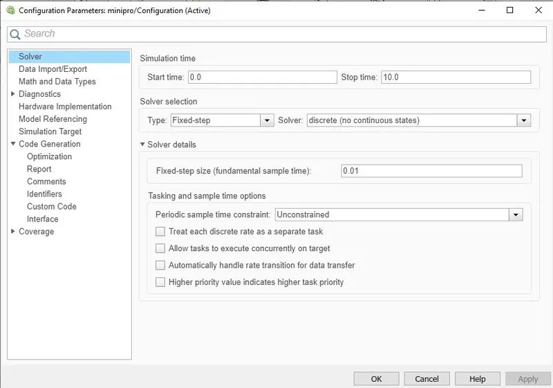
- The fixed time is set to 0.01secs.
- For sldd input, output signals, constant localizable signals have to use.
Steps:-
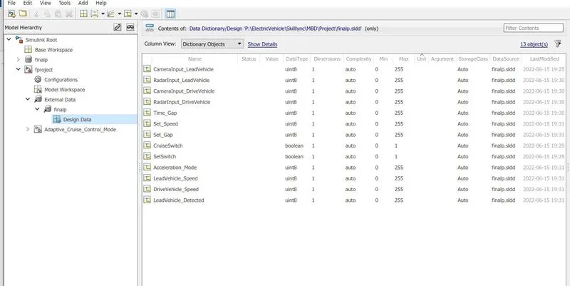
- First of all, create a sldd file according to the data given.
- And include every little notation and specify thee signals.
- Create a new folder and include every file in it otherwise, the model will not run properly.
- Make a subsystem of Adaptive cruise control.
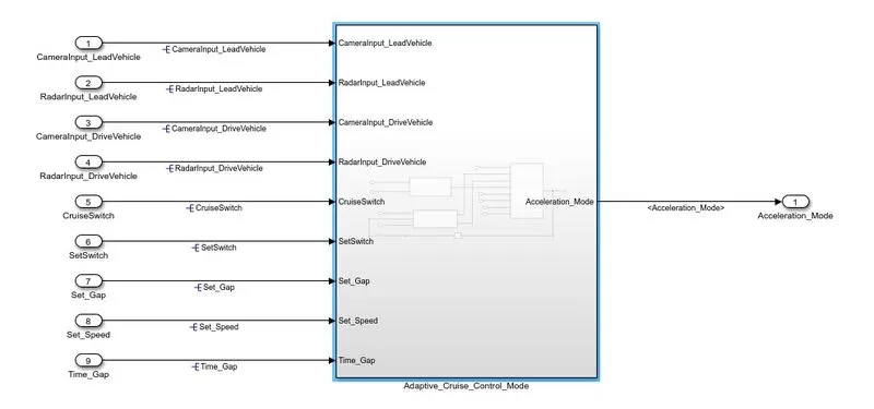
- In that subsystem three main requirements are there, Lead vehicle, Drive vehicle and cruise control algorithm.
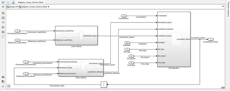
- First is the Lead vehicle it is a vehicle which is driving on the road ahead of our drive vehicle. Two input signals (Signal Name: CameraInput_LeadVehicle & RadarInput_LeadVehicle).
- Simply add both the radar & camera inputs and the output is read as Speed profile output (Signal Name: LeadVehicle_Speed).
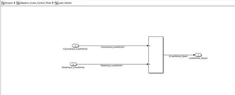
- The second is drive a vehicle it is a vehicle driven by the user & this is the vehicle which has an adaptive cruise control algorithm in it.
- Like the Lead Vehicle, the Drive Vehicle algorithm also has 2 input signals (Signal Name: CameraInput_DriveVehicle, RadarInput_DriveVehicle) & one signal coming as an Input to this subsystem (Signal Name: Acceleration_Mode) – three inputs into this requirement in total.
- Two output signals come from this subsystem (Signal Name: DriveVehicle_Speed & LeadVehicle_Detected).
- Signal DriveVehicle_Speed is a summation of three input signals mentioned above & LeadVehicle_Detected is renamed from Input Signal RadarInput_DriveVehicle by mere use of Signal Conversion block.
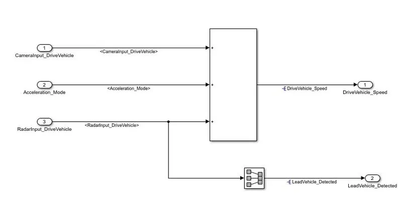
- This adaptive cruise control subsystem has three modes. off mode, on mode and stand by mode.
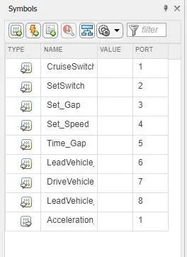
- The input signals to this state machine system are (Signal Name: Time_Gap, Set_Speed, Set_Gap, CruiseSwitch, SetSwitch).
- Output signals (Signal Name: DriveVehicle_Speed & LeadVehicle_Detected) from requirement-2 is fed back as an input signal into this state machine block.
- The output signal (Signal Name: LeadVehicle_Speed) from requirement-1 is given as an input signal to this state machine block as well.
- Output from this subsystem is a signal (Signal Name: Acceleration_Mode) which governs the vehicle speed of the drive vehicle and automatically adjusts its speed & velocity to match the lead vehicle.
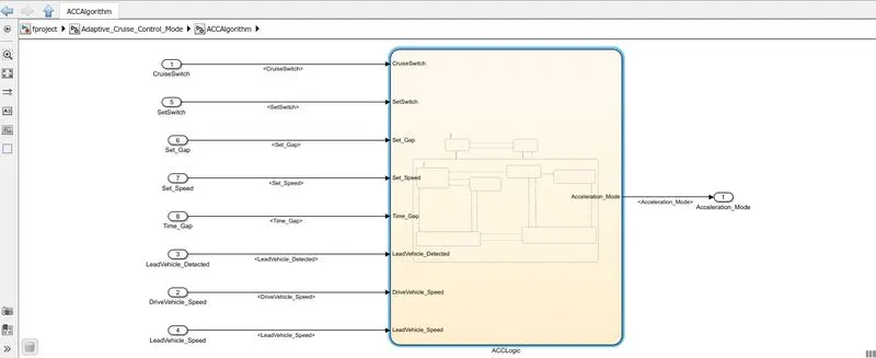
- Input parameters according to the logic chart.
- The default state inside machine logic Output signal Acceleration_Mode is at value 0 in this state.
- This state is controlled by the input signal CruiseSwitch.
- If CruiseSwitch is = 1, state Acc standby mode will get activated. If CruiseSwitch is equal to 0, state Acc off mode will get activated, from either Acc on mode or Acc standby mode.
- The second state inside machine logic output signal Acceleration_Mode is at value 1 in this state. This state is controlled by both input signals CruiseSwitch & SetSwitch.
- If CruiseSwitch is = 1, ACC standby mode will get activated. If CruiseSwitch is = 0, state acc off mode will get activated, from either acc on mode or acc standby mode.
- If SetSwitch is = 1, state acc on the mode will get activated. If SetSwitch is = 0, state acc standby mode will be on.
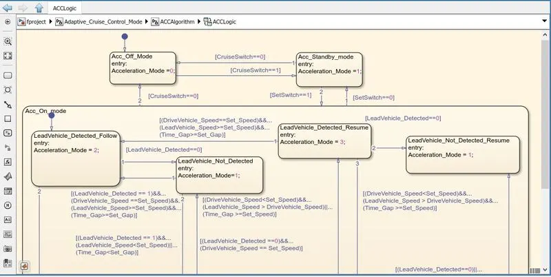
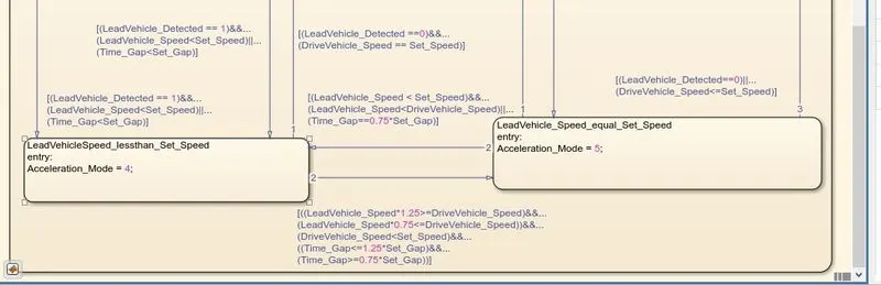
- On state will be activated when the input signal SetSwitch is = 1. There are 6 sub-states to this state logic:
- LeadVehicle_Detected_Follow (Default)
- LeadVehicle_Not_Detected
- LeadVehicle_Detected_Resume
- LeadVehicle_Not_Detected_Resume
- LeadVehicle_Speed_lessthan_Set_Speed
- LeadVehicle_Speed_equal_Set_Speed
These all are elaborated on here in given image.
- The next step is to solve signals and propagate them.
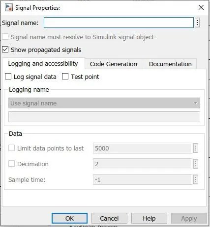
- As given below image select one signal > properties and give a signal name with a checkbox with signal name must resolve.
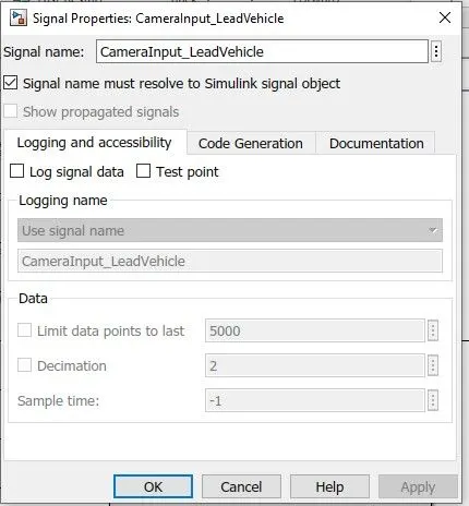
- To propagate a select signal go to Properties and check show propagated signals another option is to select signal double click and then write <> signal will be propagated.
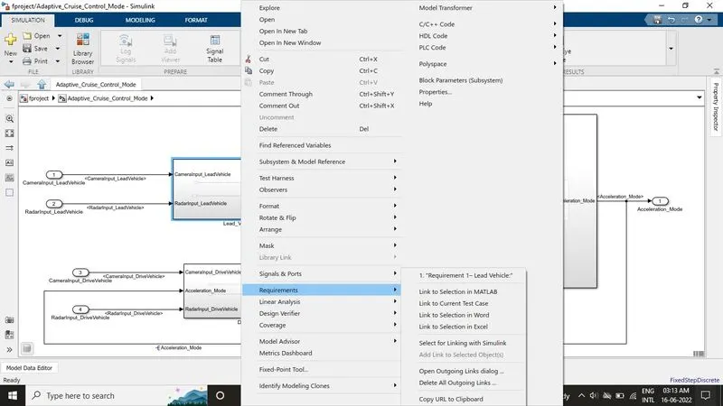
- To tag, the system select requiremtn1 subsystem right-clicks> requirements and select link to word it will link to the word file and information will be open of that subsystem.
- Same process with requirement 2.
- Change the solver configuration settings from variable time step to fixed-step with discrete solver and stepsize would be 0.01seconds.
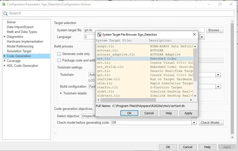
- Choose the target file ert.tlc embedded codder.
- To Check errors and warnings model advisor check must comply with different guidelines.
- Open model advisor check and just select modelling standards with MAB.
- This model has zero failures and 16 warnings.
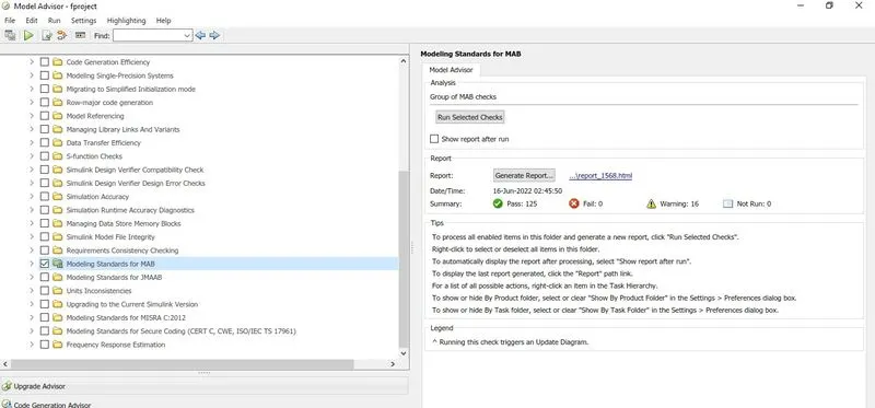
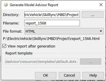
- It will generate a report with warnings fails and pass. Minimum warnings and failures should be there. It will create a report in HTML and saves it in a folder.
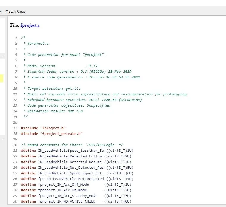
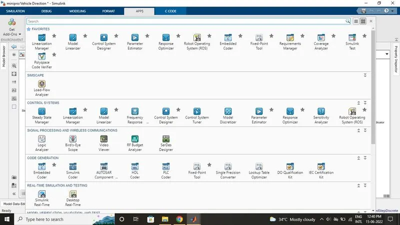
- To generate code go to APPS >Simulink coder.
- To generate code system target file should be in grt.tlc format then only it generates C code.
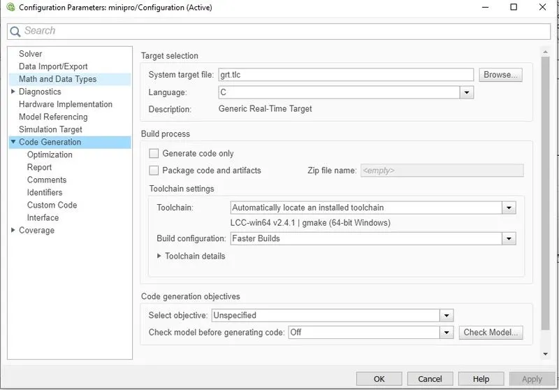
- Now select the build option to generate the whole system code.

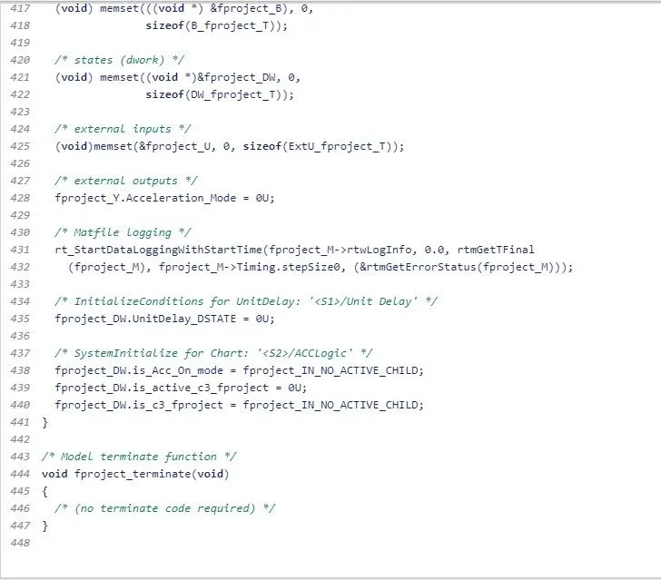
- Code file will generate with .c extension and we can see in the base workspace too.