Project 2 Adaptive Cruise Control
Objective -
- To develop Adaptive Cruise Control feature as per the Requirement Document following MAB Guidelines using MATLAB Simulink.
- To generate the C code for the model developed.
Development of the Model -
1. Creation of Data Dictionary File -
- In the Modelling tab, select Link to Data Dictionary.
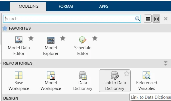
Fig 1 - Link to Data Dictionary Option in Modelling Tab
- The sldd file creation window will open.
- Add a New File and rename the file.
- Also, uncheck the "Enable model access to base workspace".
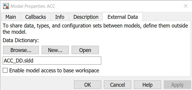
Fig 2 - Link to Data Dictionary Dialogue Box
- Click OK.
- From the Modelling tab, open Model Explorer.
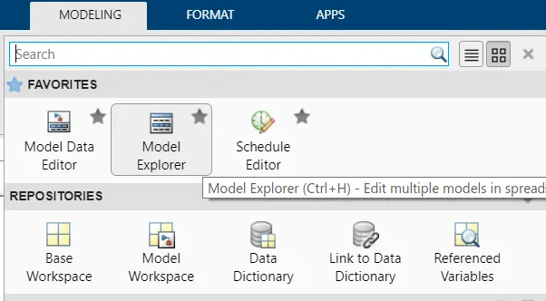
Fig 3 - Model Explorer in Modelling Tab
- In the Model Explorer window, locate the sldd file in the External Data.
- Make entries to sldd file from the Requirement Document.
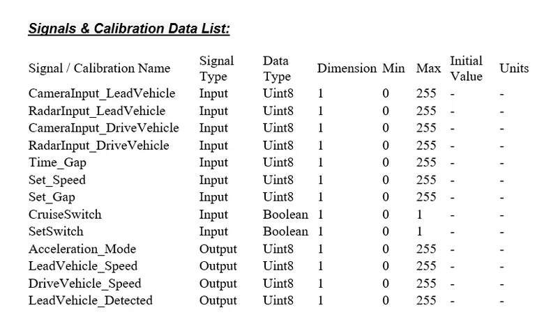
Fig 4 - Signals and Parameters List from Required Document
- For the Input Signal,Storage Class used is ImportedExtern.
- For the Output Signal, Storage Class used is Export to File.
- For the Local Signal, Storage Class used is Localizable.
- For the Clibration Signal, Storage Class used is Const.
- After making all the entries in the sldd file, Save the file.
- The sldd file is shown below in Fig 5 after making all entries.
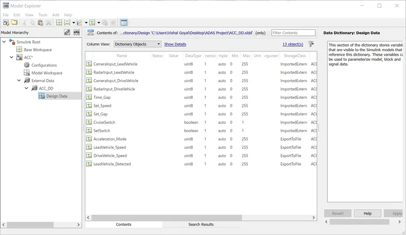
Fig 5 - sldd File after making all entries
2. Model Settings -
- In the model settings, Solver Configuration and Code Generation setting is configured.
- In the Solver Configuration, the solver is set to Fixed Step Discrete solver.
- The Step Size is given as 0.01 as provided in the Required Document.
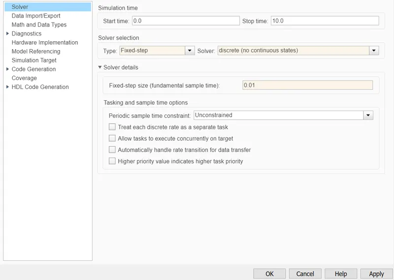
Fig 6 - Solver Setting
- In the Code Generation settings, the Embedded Coder file ert.tlc is selected as System Target File.
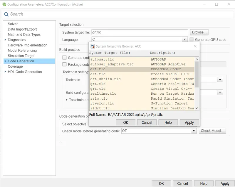
Fig 7 - Code Generation Settings
- In the Code Generation Setting, in the Interface setting check the box for Support Floating Numbers.
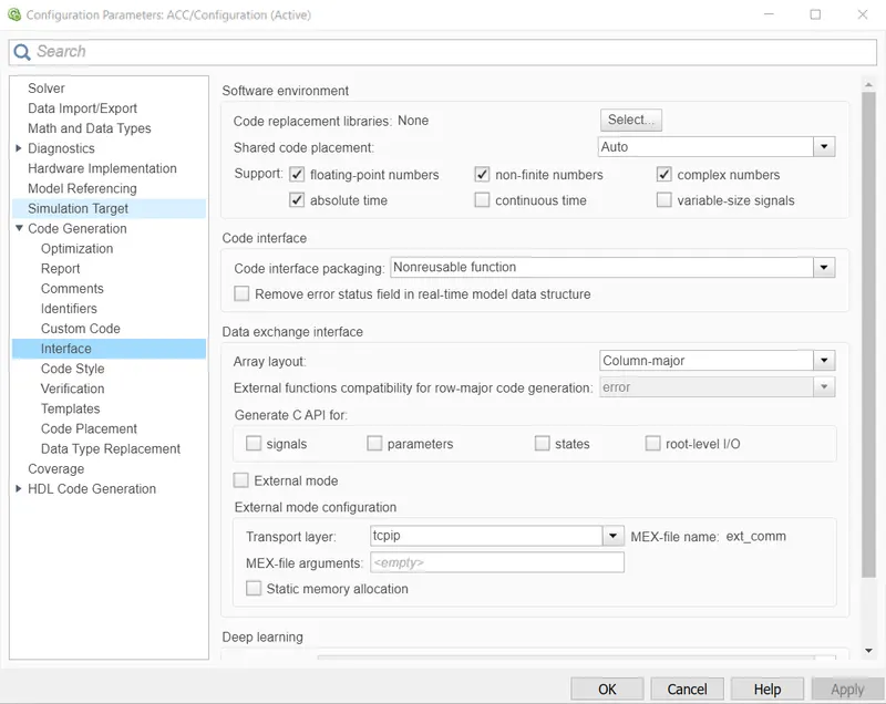
Fig 8 - Code Generation Interface Settings
3. Model Development -
- As provided in the Required Document, the Input Signals are
- CameraInput_LeadVehicle
- RadarInput_LeadVehicle
- CameraInput_DriveVehicle
- RadarInput_DriveVehicle
- Time_Gap
- Set_Speed
- Set_Gap
- CruiseSwitch
- SetSwitch
- And the Output Signal is Acceleration_Mode.
- A Subsystem is created to implement the required logic.
- This Subsystem is named as Adaptive_Cruise_Control_Logic.
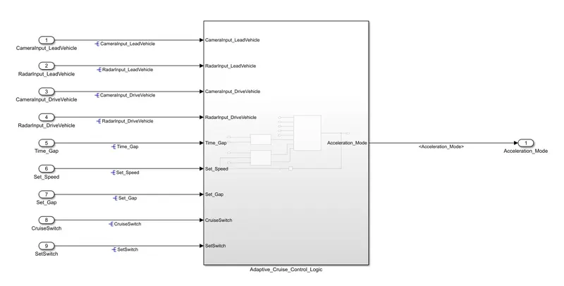
Fig 9 - Model for Adaptive Cruise Control
- The inputs and outputs of this subsystem is same as of Input and Outputs of the Model.
- For each Requirement a separate Subsystem is created and name of subsystem is as present in Subsystem.
- For this model, Three requirements are given so Three subsystems are created namely Lead_Vehicle, Drive_Vehicle and ACC_Algorithm.
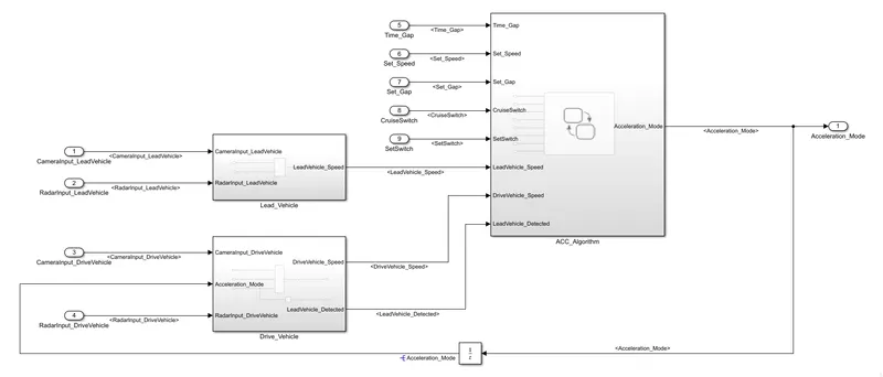
Fig 10 - Separate Subsystem for Separate Requirement
- For Requirement 1 -
- Lead Vehicle is a vehicle which is driving in the road ahead of our drive vehicle.
- Two input signals for this are CameraInput_LeadVehicle & RadarInput_LeadVehicle.
- Add both the radar & camera inputs & the corresponding output is read as Speed profile output LeadVehicle_Speed.
- Speed data of the lead vehicle is critical in implementing the Adaptive Cruise Control algorithm.
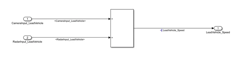
Fig 11 - Requirement 1 Lead_Driver
- For Requirement 2 -
- Drive Vehicle is the vehicle driven by the user & this is the vehicle which has ACC algorithm in it.
- Like the Lead Vehicle, Drive Vehicle algorithm also has 2 input signals CameraInput_DriveVehicle, RadarInput_DriveVehicle & one signal coming as an Input to this subsystem Acceleration_Mode – three inputs into this requirement in total.
- Two output signals come from this subsystem DriveVehicle_Speed & LeadVehicle_Detected.
- Signal DriveVehicle_Speed is summation of three input signals mentioned above & LeadVehicle_Detected is renamed from Input Signal RadarInput_DriveVehicle by mere use of Signal Conversion block.
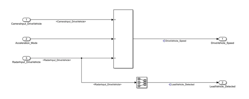 Fig 12 - Requirement 2 Drive_Vehicle
- For Requirement 3 -
- Adaptive Cruise Control feature has 3 major modes of operation: OFF Mode, STANDBY Mode & ON Mode.
- This particular requirement has to be implemented as state machine logic in Simulink.
- The input signals to this state machine system are Time_Gap, Set_Speed, Set_Gap, CruiseSwitch, SetSwitch.
- Also, the output signals DriveVehicle_Speed & LeadVehicle_Detected from requirement-2 is fed back as an input signal into this state machine block.
- Additionally, output signal LeadVehicle_Speed from requirement-1 is given as an input signal to this state machine block as well.
- Output from this subsystem is a signal Acceleration_Mode which governs the vehicular speed of the drive vehicle which automatically adjusts its speed & velocity to match the lead vehicle.
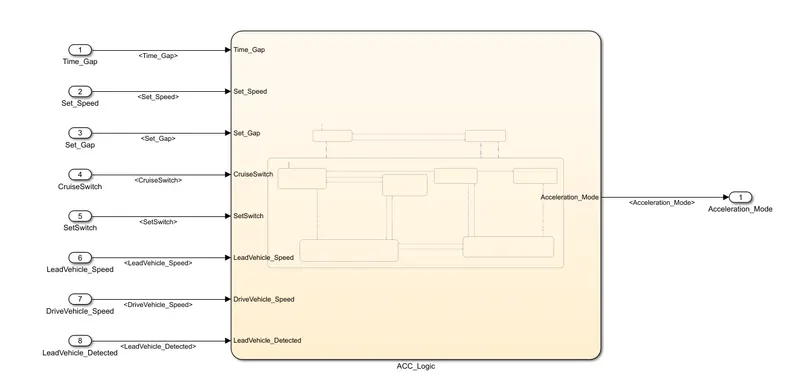
Fig 13 - Requirement 3 ACC_Logic
- The chart development conditions are given in the Requirement Document.
- ACC OFF MODE state logic -
- This is the default state inside state machine logic.
- Output signal Acceleration_Mode is at value 0 in this state.
- This state is governed by input signal CruiseSwitch.
- If CruiseSwitch is equal to 1, state ACC STANDBY mode will get activated.
- If CruiseSwitch is equal to 0, state ACC OFF mode will get activated, from either ACC ON mode or ACC STANDBY mode.
- ACC STANDBY MODE state logic -
- This is the second activated state inside state machine logic.
- Output signal Acceleration_Mode is at value 1 in this state.
- This state is governed by both input signals CruiseSwitch & SetSwitch.
- If CruiseSwitch is equal to 1, state ACC STANDBY mode will get activated.
- If CruiseSwitch is equal to 0, state ACC OFF mode will get activated, from either ACC ON mode or ACC STANDBY mode.
- If SetSwitch is equal to 1, state ACC ON mode will get activated.
- If SetSwitch is equal to 0, state ACC STANDBY mode will get activated.
- ACC ON MODE state logic -
- This state will be activated when input signal SetSwitch is equal to 1.
- There are 6 sub states to this state logic that are:
- LeadVehicle_Detected_Follow (Default)
- LeadVehicle_Not_Detected
- LeadVehicle_Detected_Resume
- LeadVehicle_Not_Detected_Resume
- LeadVehicle_Speed_lessthan_Set_Speed
- LeadVehicle_Speed_equal_Set_Speed
- LeadVehicle_Detected_Follow state logic -
- This is the default sub state inside ACC ON MODE state.
- Output signal Acceleration_Mode is equal to 2.
- Condition to transit from LeadVehicle_Detected_Follow to LeadVehicle_Not_Detected, Input signal condition LeadVehicle_Detected == 0.
- Condition to transit from LeadVehicle_Detected_Follow to LeadVehicle_Speed_lessthan_Set_Speed, Input Signals condition (LeadVehicle_Detected == 1) && (LeadVehicle_Speed < Set_Speed) || (Time_Gap < Set_Gap).
- LeadVehicle_Not_Detected state logic -
- Output signal Acceleration_Mode is equal to 1.
- Condition to transit from LeadVehicle_Not_Detected to LeadVehicle_Detected_Follow, Input signals condition [(LeadVehicle_Detected==1) && (DriveVehicle_Speed == Set_Speed) && (LeadVehicle_Speed >= Set_Speed) && (Time_Gap >= Set_Gap)].
- Condition to transit from LeadVehicle_Not_Detected to LeadVehicle_Speed_lessthan_Set_Speed, Input signals condition [(LeadVehicle_Detected == 1) && (LeadVehicle_Speed < Set_Speed) || (Time_Gap < Set_Gap)].
- LeadVehicle_Detected_Resume state logic -
- Output signal Acceleration_Mode is equal to 3.
- Condition to transit from LeadVehicle_Detected_Resume to LeadVehicle_Detected_Follow, Input signals condition [(DriveVehicle_Speed == Set_Speed) && (LeadVehicle_Speed >= Set_Speed) && (Time_Gap >= Set_Gap)]
- Condition to transit from LeadVehicle_Detected_Resume to LeadVehicle_Not_Detected_Resume, Input signal condition LeadVehicle_Detected==0.
- Condition to transit from LeadVehicle_Detected_Resume to LeadVehicle_Speed_equal_Set_Speed, Input Signal condition [(DriveVehicle_Speed < Set_Speed) && (LeadVehicle_Speed > DriveVehicle_Speed) && (Time_Gap >= Set_Gap)]
- LeadVehicle_Not_Detected_Resume state logic -
- Output signal Acceleration_Mode is equal to 1.
- LeadVehicle_Speed_lessthan_Set_Speed state logic -
- Output signal Acceleration_Mode is equal to 4.
- Condition to transit from LeadVehicle_Speed_lessthan_Set_Speed to LeadVehicle_Not_Detected, Input signal condition [(LeadVehicle_Detected == 0) && (DriveVehicle_Speed == Set_Speed)]
- Condition to transit from LeadVehicle_Speed_lessthan_Set_Speed to LeadVehicle_Speed_equal_Set_Speed, Input signals condition [((LeadVehicle_Speed*1.25>=DriveVehicle_Speed) && (LeadVehicle_Speed * 0.75<=DriveVehicle_Speed)) && (DriveVehicle_Speed < Set_Speed) && ((Time_Gap<=1.25*Set_Gap) && (Time_Gap >=0.75*Set_Gap))]
- LeadVehicle_Speed_equal_Set_Speed state logic -
- Output signal Acceleration_Mode is equal to 5.
- Condition to transit from LeadVehicle_Speed_equal_Set_Speed to LeadVehicle_Not_Detected_Resume, Input signal conditions is [(LeadVehicle_Detected == 0) || (DriveVehicle_Speed <= Set_Speed)]
- Condition to transit from LeadVehicle_Speed_equal_Set_Speed to LeadVehicle_Detected_Resume, Input signal conditions [(DriveVehicle_Speed < Set_Speed) && (LeadVehicle_Speed > DriveVehicle_Speed) || (Time_Gap >= Set_Gap)]
- Condition to transit from LeadVehicle_Speed_equal_Set_Speed to LeadVehicle_Speed_lessthan_Set_Speed, Input signals conditions [(LeadVehicle_Speed<Set_Speed) && (LeadVehicle_Speed<DriveVehicle_Speed) || (Time_Gap == 0.75*Set_Gap)]
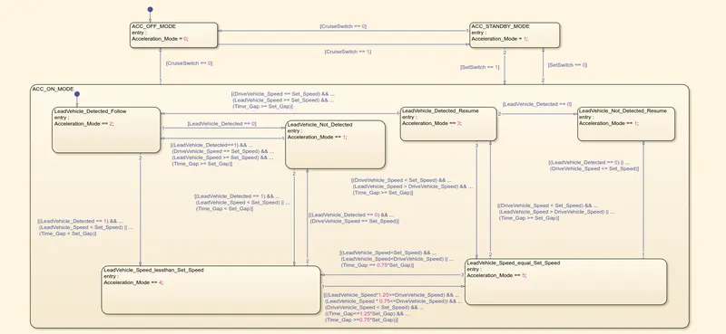
Fig 14 - Requirement 3 State Chart
- After creating the state logic, open the Symbols Pane and define the parameters data type used in the state chart.
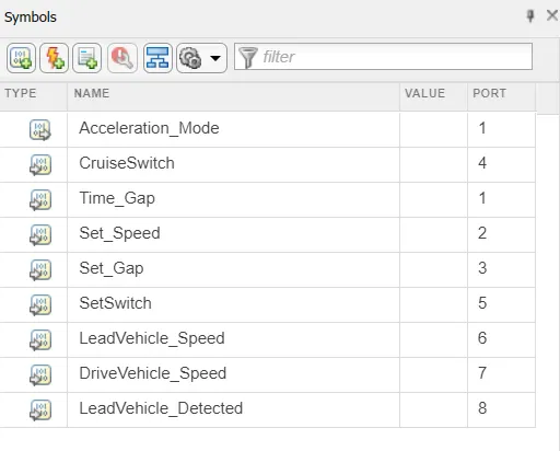
Fig 15 - Symbols Pane
- Also, in the Model Explorer edit the data types for the signals used in state chart.
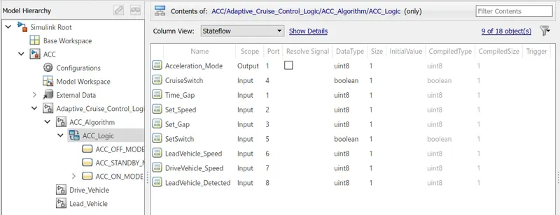
Fig 16 - Symbols Pane
4. Signal Tagging -
- The signals present in sldd file are need to named and tagged in the model.
- When the signal is originated for the first time, this signal need to be Resolved.
- When the resolved signal goes into different subsystem it needs to be Propagated.
- It can be done either using Property Inspector or Right click the Signal and select Signal Properties.
- To resolve the signal, select the signal.
- In the Signal Properties, give the name of the signal and check the box "Signal name must resolve to Simulink signal object".
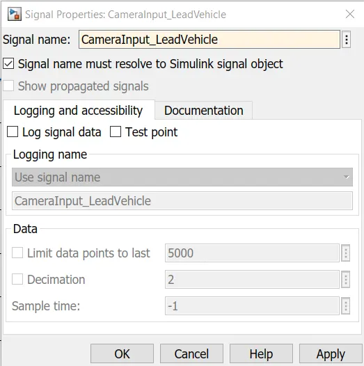
Fig 17 - Signal Resolving
- A blue colour symbol will appear in front of Signal name after resolving as shown in Fig 18.
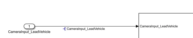
Fig 18 - Resolved Signal
- As this signal goes into the subsystem it is needed to propagated because one signal is resolved for only one time at the point of origination.
- To propagate the signal after resolving, right click the signal and select Properties.
- In the Signal Properties, tick the second check box "Show Propagated Signal".
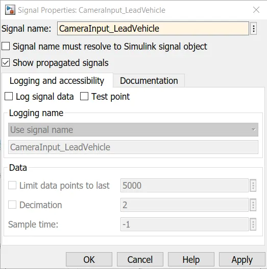
Fig 19 - Signal Propagate
- This Propagated Signal show between < > symblos.

Fig 20 - Propagated Signal
- This resolving and propagation is done for all signals present in sldd file.
5. Requirement Tagging -
- The Requirement Tagging is the process of linking the model with the description present in the Requirement Document.
- This tagging is done for all the requirement subsystem present in the model.
- To Tag the subsystem, select the description in Required Document which has to linked with the model.
- Right Click the subsystem.
- Select the Link to Selection in Word in the Requirements Options.
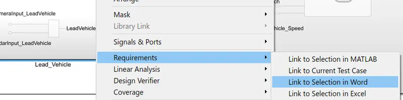
Fig 21 - Requirement Tagging
- The link is created.
- To check the link created, again right click on subsystem and go to Requirements options.
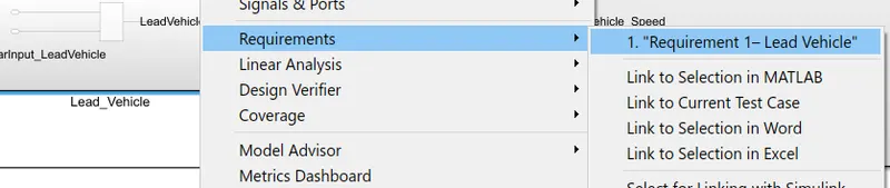
Fig 22 - Requirement Tag
- This tagging is done for all the requirement subsystem created.
6. Model Advisor Check -
- To check the model developed is according to MAB guidelines or not.
- To run this check, go to Modelling Tab.
- Open Model Advisor.
- Select the whole system in the System Selector.
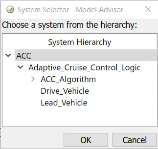
Fig 23 - Model Advisor System Selector
- Model Advisor Dialogue Box will Open.
- In this Advisor menu, uncheck all the check boxes and expand the By Task Option.
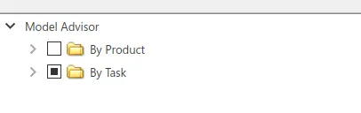
Fig 24 - Model Advisor Checks Select
- After expanding the By Task option, select only Modelling Standards for MAB.
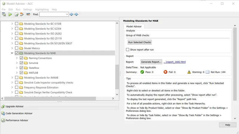
Fig 25 - Modelling Standards for MAB
- This option contain a total of 144 checks.
- Click on Run Selected Checks.
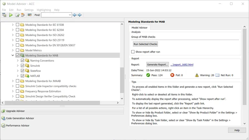
Fig 26 - Model Advisor MAB conditions Checks
- For the model developed out of 144 checks, it passes 124 checks and the remaining 20 checks are warnings.
- The number of warnings can be reduced by clicking the checks containing yellow exclamatory mark.
- In the description of the selected check, cause of warning and its redeemption is given.
- Follow the instructions and try to reduce as much warnings as possible.
- After removing all possible warnings, again run the checks with warning sign.
- It will show the pass green mark.
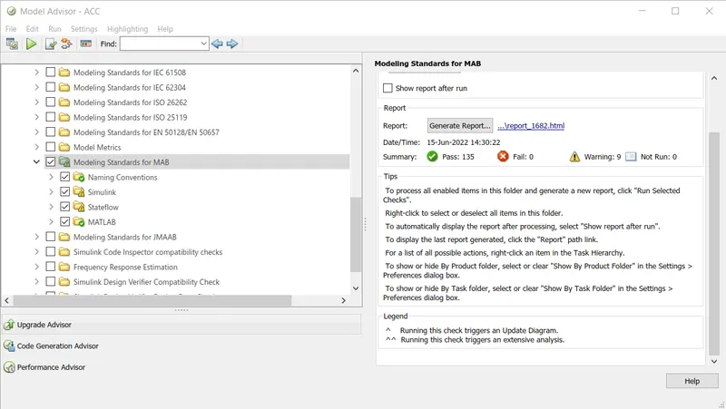
Fig 27 - MAB Analysis after Removing all Possible Warnings
- After removing all possible warnings, th e number of warnings reduced to 9.
- After this Generate Report for the Checks Done in Model Advisor by clicking Generate Report Option.
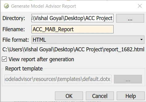
Fig 28 - Model Advisor Report Generation
- Provide Name and Directory Path in Model Advisor Report Generation Dialogue Box.
- This will generate the report.
7. Code Generation -
- For the model developed C code is generated to provide it to the Electrical Control Unit (ECU).
- To generate the code, in the Apps tab select the Embedded Coder.
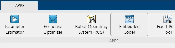
Fig 29 - Embedded Coder in Apps Tab
- Select Build Option to generate the C code for the developed model.
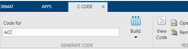
Fig 30 - Code Generation
- When the code is generated select View Code option to open the generated code file.
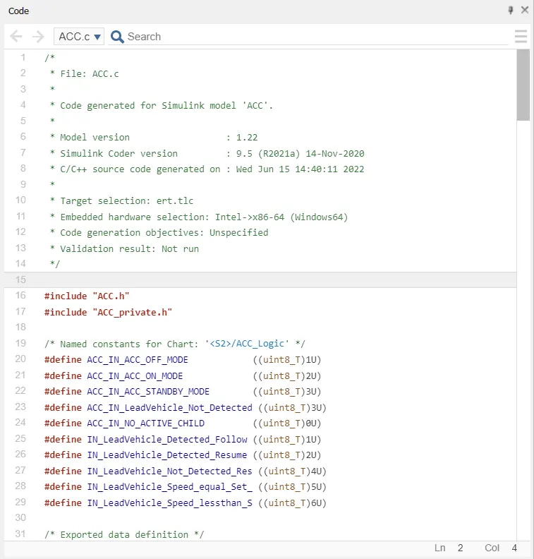
Fig 31 - Generated C Code
Conclusions -
- The Adaptive Cruise Control feature is developed successfully in MATLAB Simulink as per MAB guidelines.
- The C Code is generated for the Adaptive Cruise Control Model.
Google Drive Link for the Project Folder - Project_Adaptive_Cruise_Control