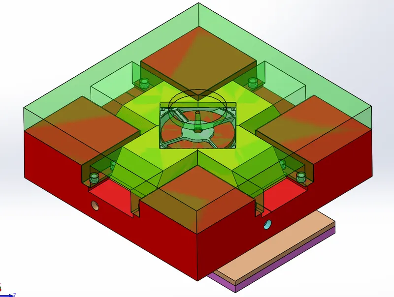
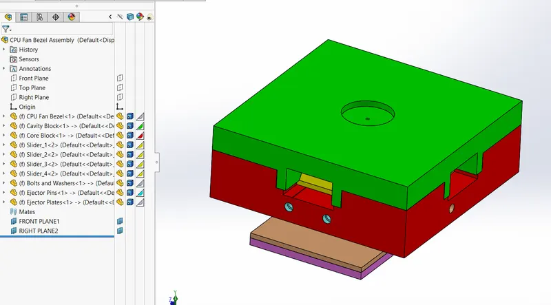
Project 2
CPU Fan Bezel
Commands Used
- Line
- Rectangle
- Circle
- Trim Entities
- Convert Entities
- Offset Entities
- Mirror Entities
- Linear sketch pattern
- Circular sketch pattern
- Extrude boss/base
- Extrude cut
- Hole Wizard
- Fillet
- Draft
- Lofted surface
- Offset surface
- Ruled surface
- Delete face
- Extend surface
- Knit surface
- Cut with surface
- Draft analysis
- Move face
- Scale
- Parting lines
- Shutoff surfaces
- Parting surfaces
- Core
- Move/copy bodies
- Combine
- Insert component
- New part
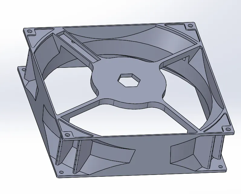
Component:
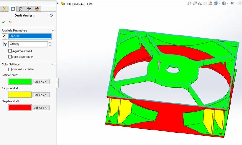
Checking Draft Analysis:
Draft analysis Examines the faces of the model for sufficient draft, to ensure that the part ejects properly from the tooling. By using draft analysis we check if there are any missing drafts in the model and do the necessary changes.
Minimum Draft angle is 0.5 degrees.
Scaling:
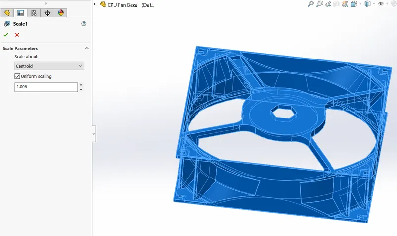
Depending on the material, the part will shrink when cooled after molding. Therefore our mold needs to be a little larger than the original so we will scale up our part.
Assuming the material for the model as ABS (shrinkage - 0.6%), the scale value is determined as (0.6/100)+1=1.006 for the model.
Parting Line:
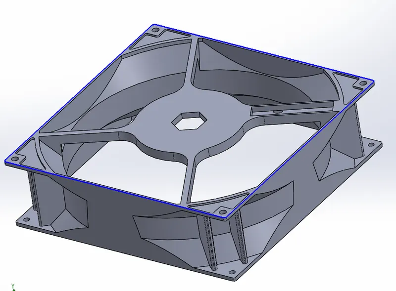
Now we need to separate the model into core and cavity. for this, we use the parting line command.Parting lines are made to separate into core and cavity.
Shut off Surface:
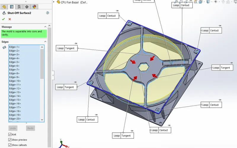
We can observe that there are few openings in the part. we have to cover these parts before creating the mold. For this, we use the shut-off surface command. All the opening holes are covered using a shut-off surface.
Shut-off surface Creates surface patches to close up through holes in the molded part.
Parting Surface:
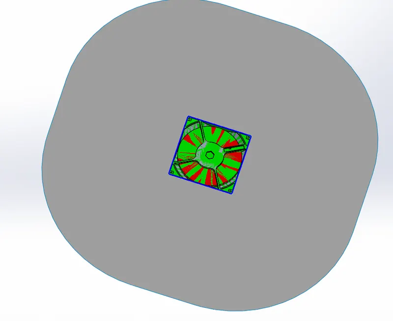
The parting surface is made along the parting line to separate the core and cavity blocks.
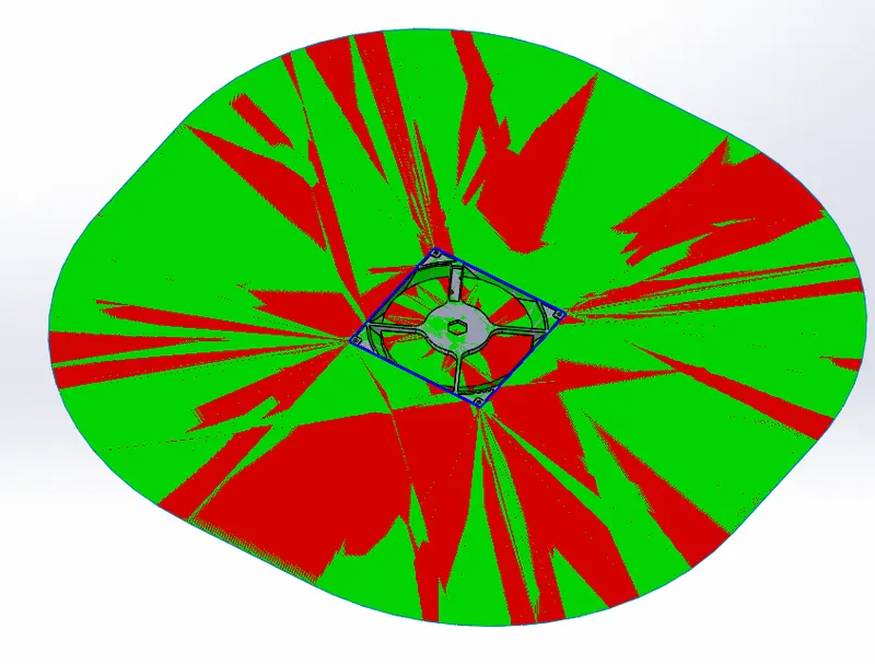
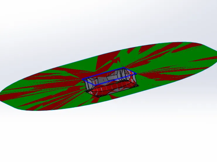
Cavity Surface
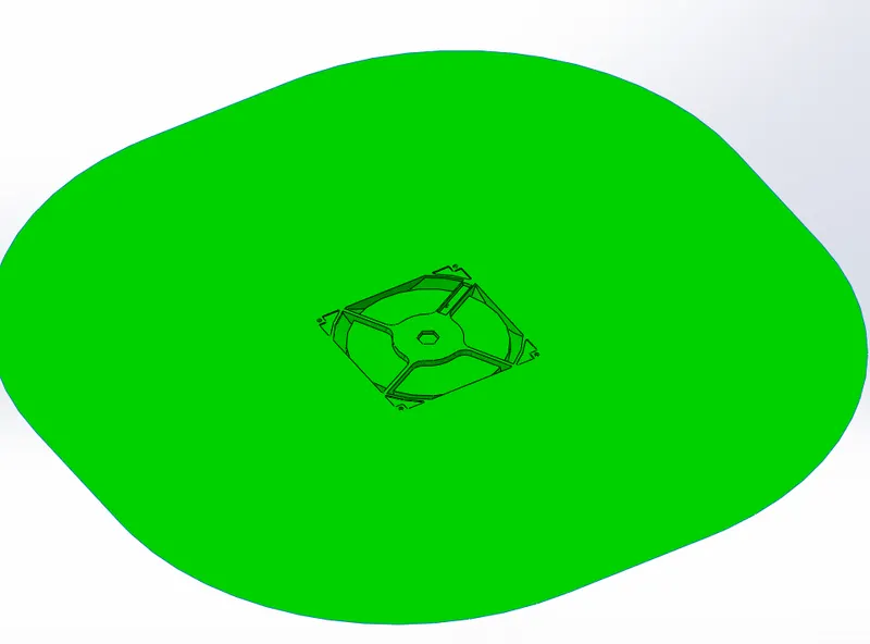
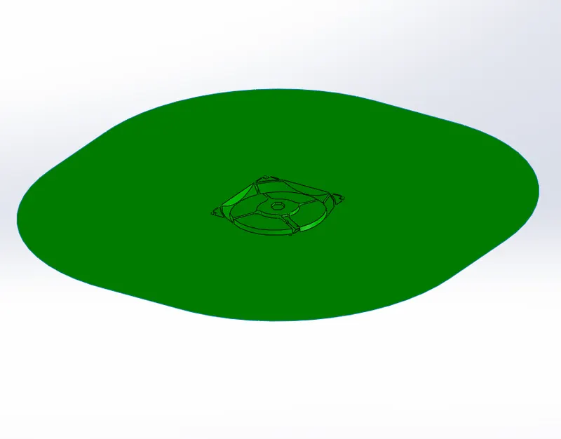
Core Surface
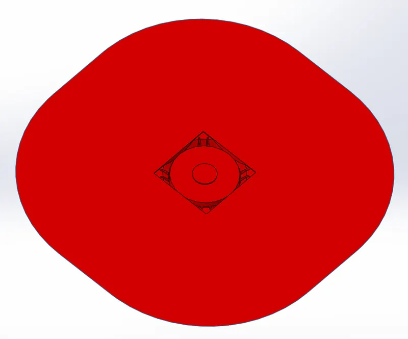
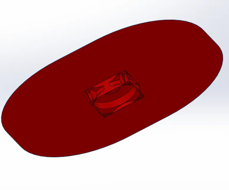
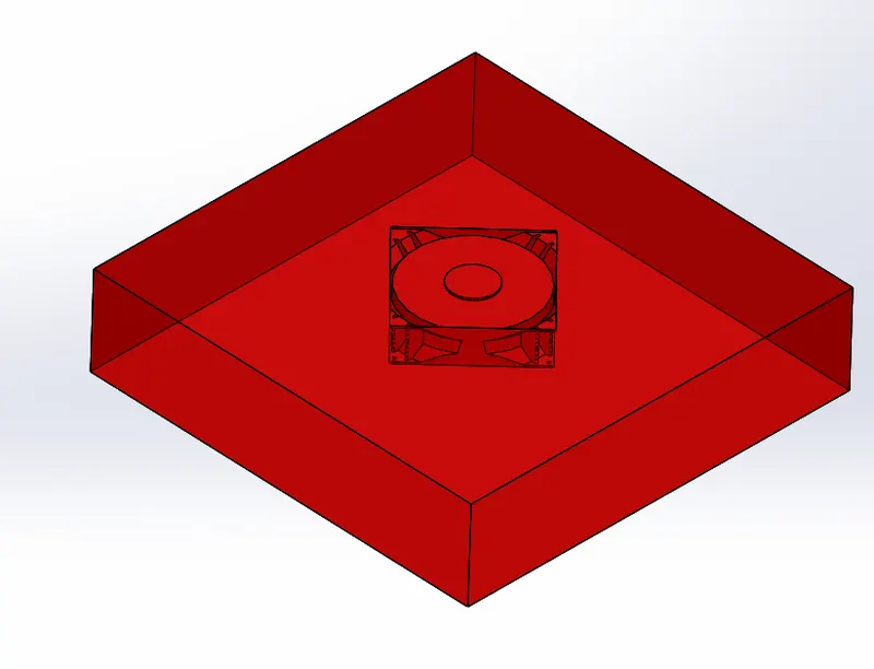
Cavity Block:
By using Cavity surface cavity block is created
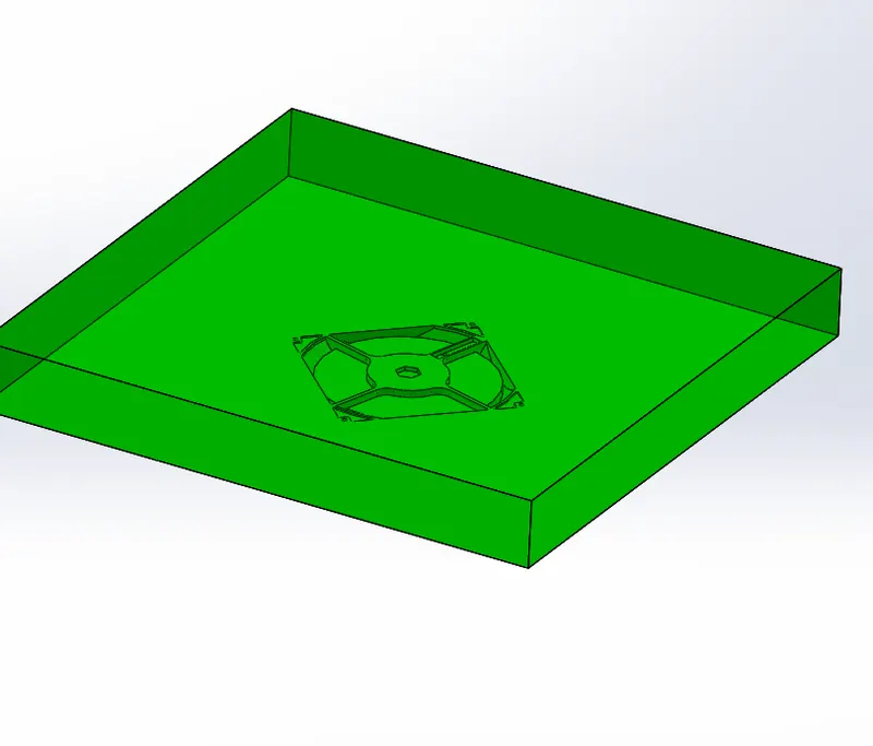
Core Block:
By using core surface core block is created
Sliders:
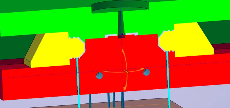
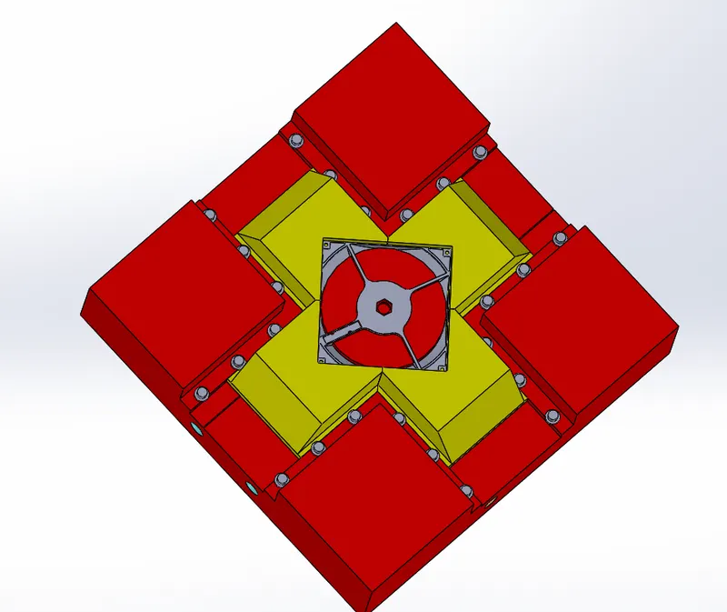
There are some Features provided at the Corners of the components those features will not satisfy the core and cavity block movements so that we need to provide sliders
Slider 1:
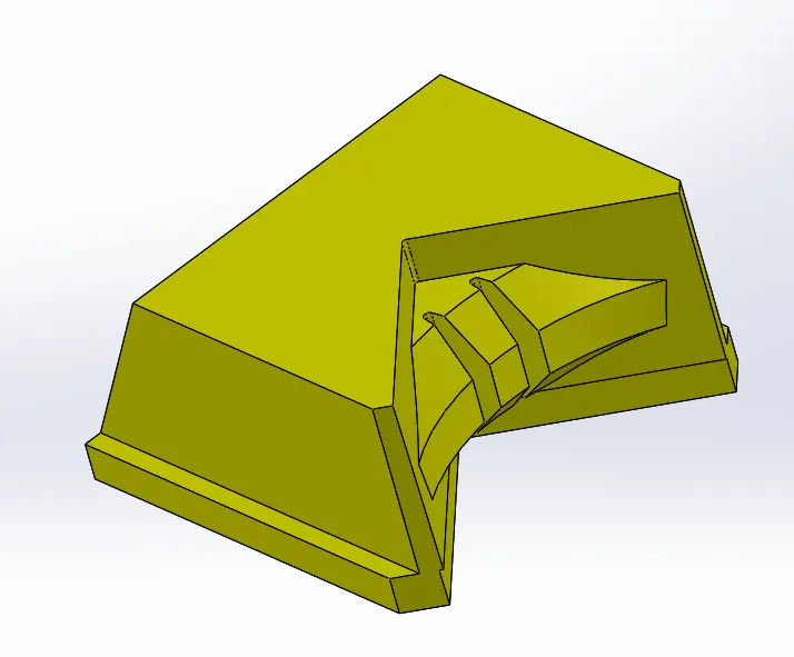
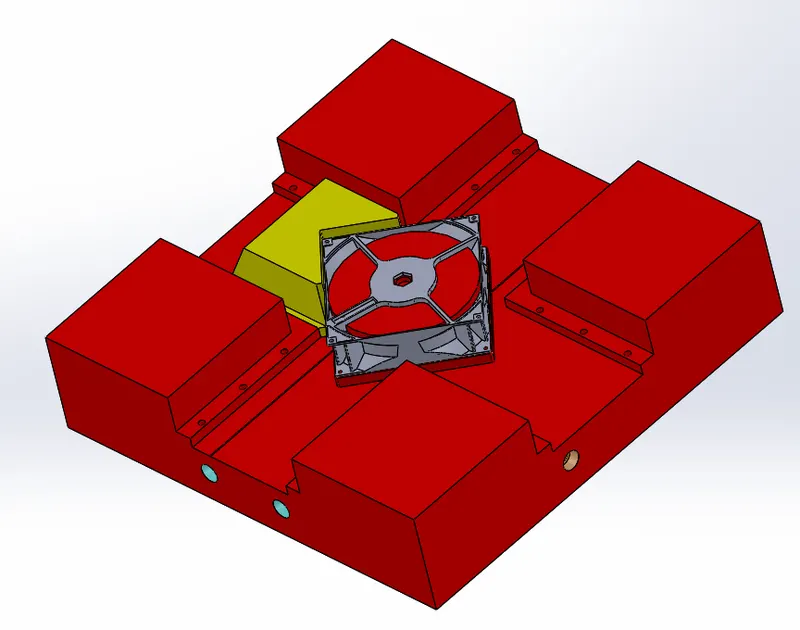
Slider 2:
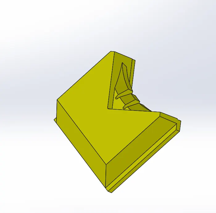
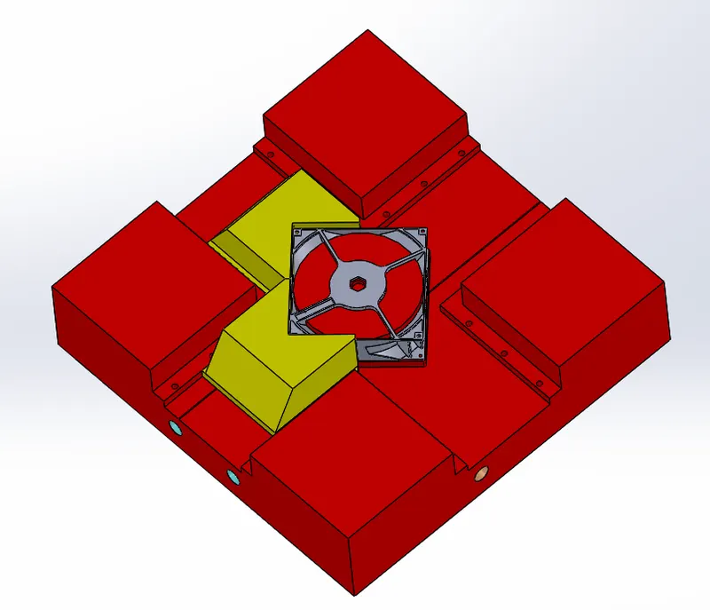
Slider 3:
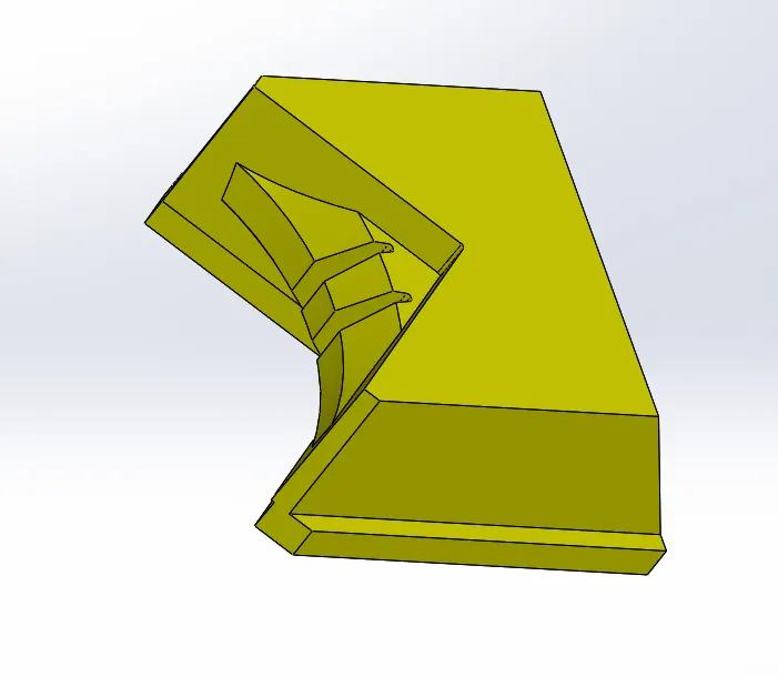
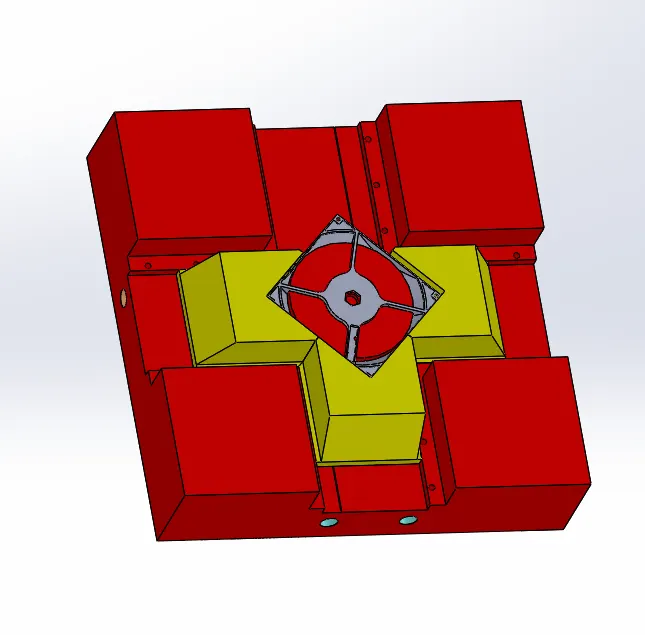
Slider 4:
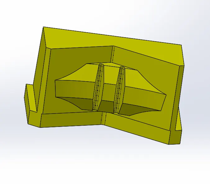
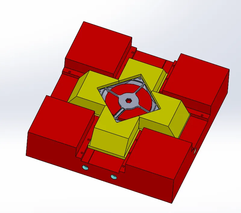
Bolts and Washers:
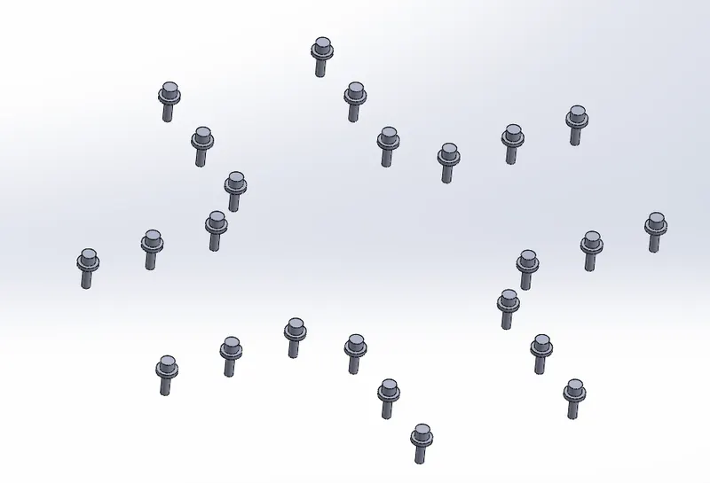
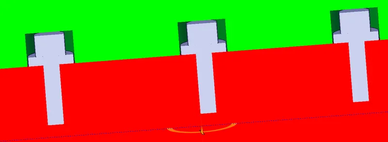
Provided Bolts and Washers for the Guides in the core block
Ejector pins and Ejector back plates:
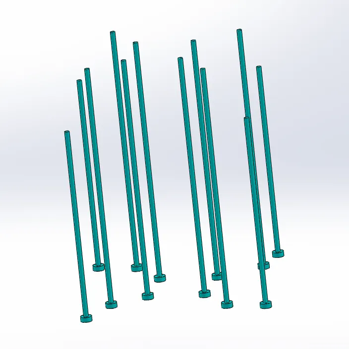
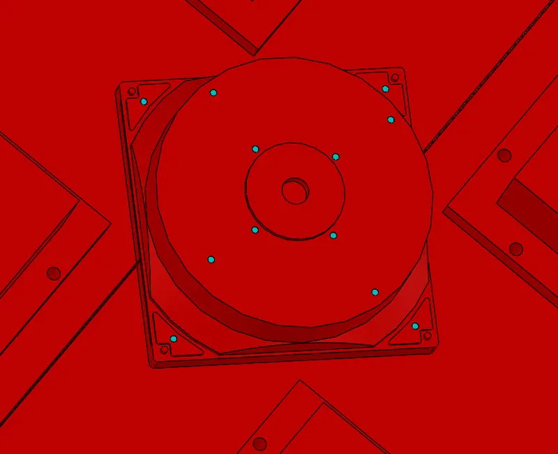
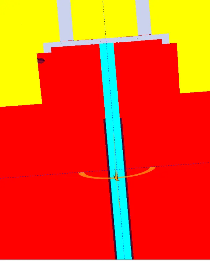
As the part needs to be ejected form the core block after the injection process, we should design ejector pins such that the ejector pins will be pushing the part with the help of ejector and ejector back plate. The heads of the ejector's pins are made based on the type of ejector pins, as the ends of ejector pins which will be in contact with the part to be ejected are in angled manner (Type-2) the heads of ejector pins should be in “D” shape.
After the design of ejector pins relief for the ejector pins should be provided both in core block and the ejector back plate.
Ejector Pins:
Ejector pins are created for ejecting the components when the core block move away from the cavity block after the part solidified
Ejector Plates:
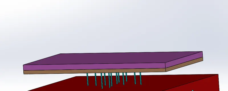
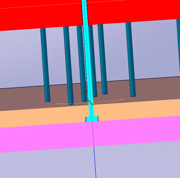
Cavity and Core Blocka are edited according to the parts
Sprue, Runner and gate system:
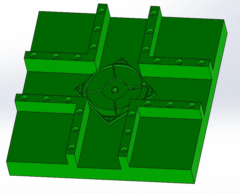
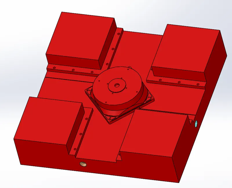
Sprue is a channel through which metal or plastic is poured into a mould trough this the molten material will be passed through the gate through runner system which will connect the sprue and gate, gate is a channel which will connect the runner and mold cavity.
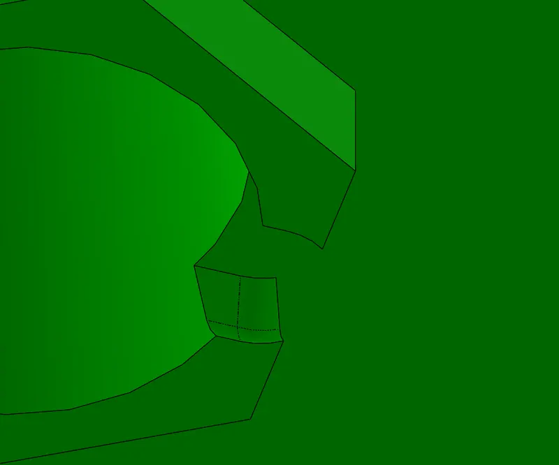
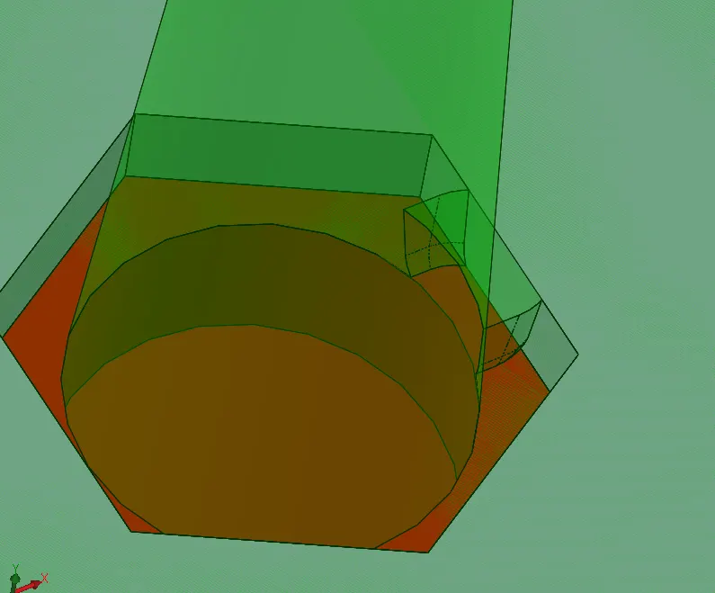
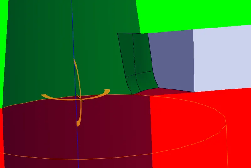
Cooling Channels:
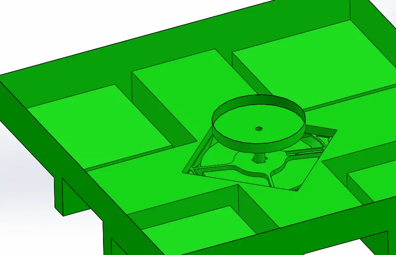
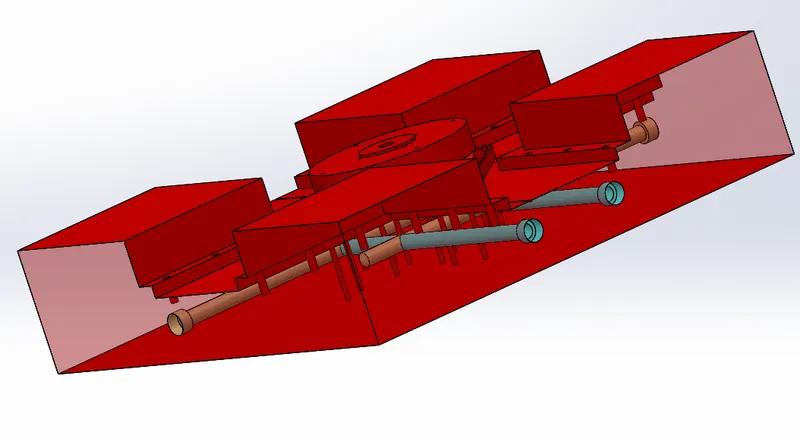
Cooling channels are required to provide uniform cooling for the part to avoid defects during solidification for this we need to provide inlet and outlet ports for the coolant to pass through the core block.
Air Vent:
Air vents need to be designed for the mold for removal of trapped air in the blocks for this a gap of 0.02mm will be provided on the core block with a way for the air to be passed out the block.
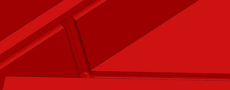
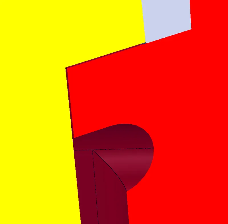
Avoided Rubbing Surface between cavity and core block