Project 2
ANSWER:
AIM: -
- Route the Wiring harness on Given Tail Gate and Prepare to flatten the view drawing in CATIA V5.
Objective:
- Route the Wiring harness on the Given car body and Prepare to flatten the view drawing in CATIA V5
- Prepare flattened view drawing in CATIA V5 Apply all packaging rules, and industry best practices.
- Apply Protection coverings as required
- Provide all necessary details like clearance, Clipping/Clamping selection, Harness fixing requirements, Harness continuity, and Assumptions if required
Design of Wire Harness
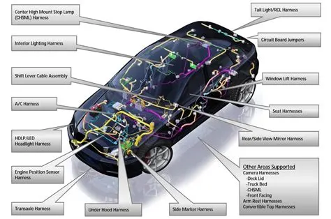
The harness design comprising the interconnected mesh of wires is crucial. Select the important components like connectors, fuses, and sensors. Ensure their reliability.
Study the schematic circuit diagram. Divide the entire vehicle into detachable parts like chassis, body, and engine. Then design the wiring harness that suits the requirements. Ensure that it fits the customer's requirements, shape, and size of the vehicle. Chalk out electrical routing in a way that reduces complexity and uses minimal space.
There are three types of engine wire harnesses based on the vehicle part you are looking at. The engine wire harness is a set of wires, connectors, and terminals to relay the signal to and from the engine. It also communicates messages from all sensors within the engine.
The body wiring harness routes electrical and electronic bits of information. It’s what keeps the major components of the automobile working. The body wiring takes care of power windows, lighting, and other accessories. And then, you need a chassis wiring harness for connecting the components.
Packaging rules and assumptions made in this project
- Avoid harness routing and clipping in the blind zone
- Provide additional slack to the harness according to the surrounding. 5-10% of slack is enough.
- Provide enough clearance to the wiring harness concerning the surrounding. • Provide a guide channel if required
- Use available holes for clamp and clip mounting
- Enough clamps to be provided to ensure positive clearance with surrounding and safety of the wiring harness.
- Distance between two clamps on a straight branch should be a maximum of 200mm.
- Use a rubber grommet that provides proper sealing, protects the harness from sharp
- edges, protects against vibration, and even acts as a clamp. • Branch length should be a minimum of 50 mm
- Minimum distance between the clip and nearest branching point should be 25mm
- Minimum distance between two breakouts should be 50mm
- Limit the number of branches from a single branching point to 4.
- Provide bracket for interconnection connector parking
1. Download the car body model on which the wiring harness is to be routed:- The tailgate module is downloaded as a .igs file, which is then saved as a CAT.PRODUCT, for easy handling of large assembly this CAT.product is converted to a single CAT.PART. And managed in a separate product file as Back_Door.part.
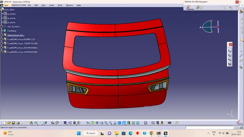
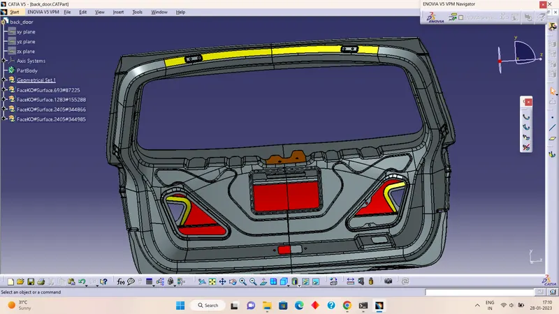
2. Creating Context Assembly:-
Context assembly is created as (Assy_Car_BackDoor_Harness_Context).
3. Define Electrical devices in the electrical part design module:-
In this model, 5 connectors are used, of which one is an interconnection connector, and 4 others are connectors for lights, two of which are used for backlights, and the left is used for number plate lights.
The connectors used are:
- Brake Light Assembly Connections – 2(LH and RH) [C-DT-06-08SA-CE13]
- Inter connection Connector – 1 [C-776438-4]
- Top mounted stop light connector – 1
- C-DT04-08PA is used for the number plate light.
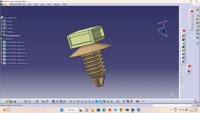
- We are using furr_tree_clips.
Here we have defined them as given below
- Downloading the connector 3D part
- Creating the required geometrical parameters
- Define the part as an electrical connector
- Define bundle connection point
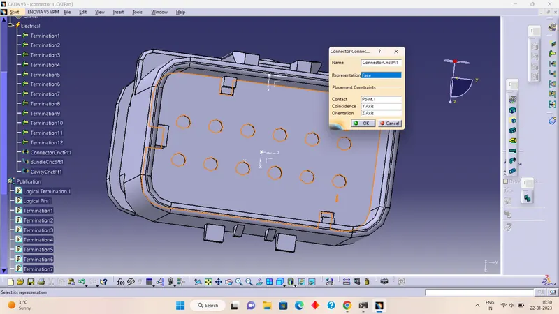
- Define connector connection point.
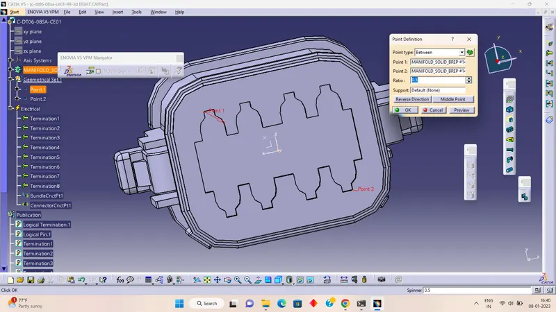
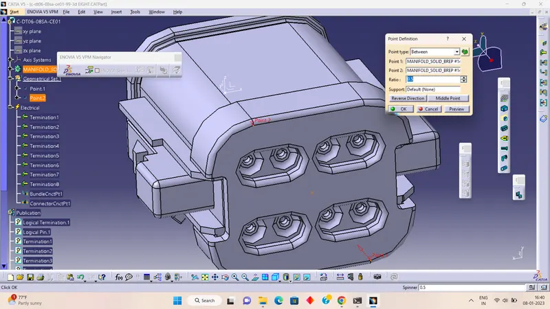
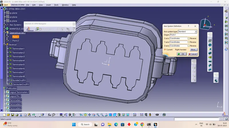
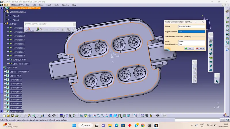
We have defined the connector connection assembly below by defining the connector connection point and cavity connection point.
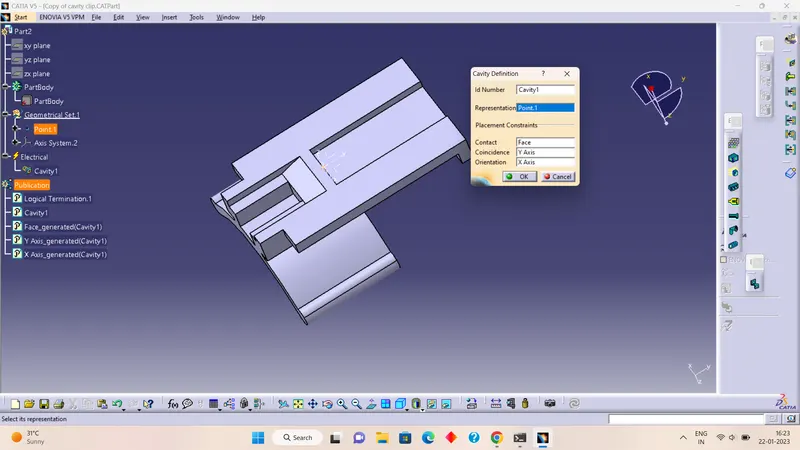
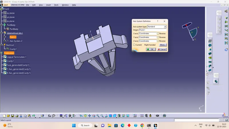
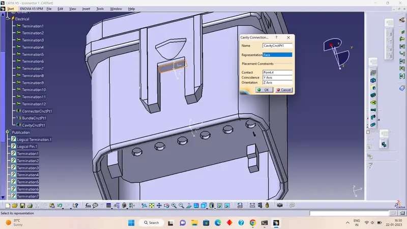
Defining all the required parameters and assembling the connect electrically electrical assemble
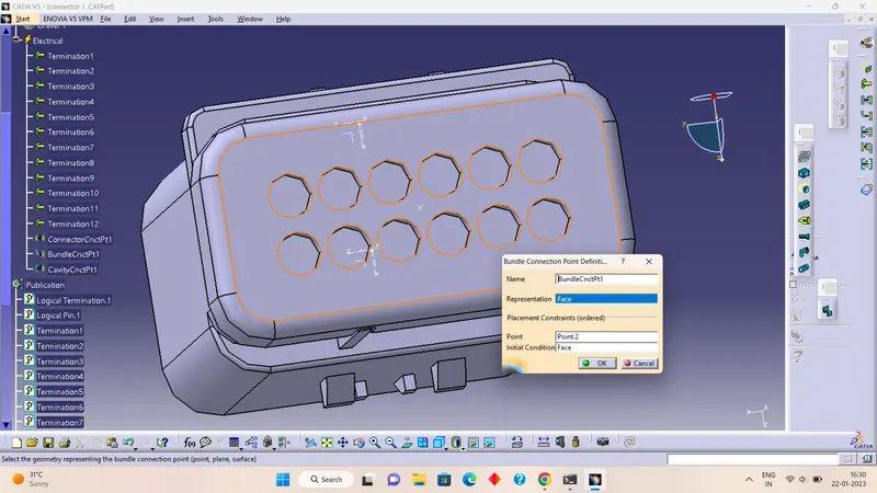
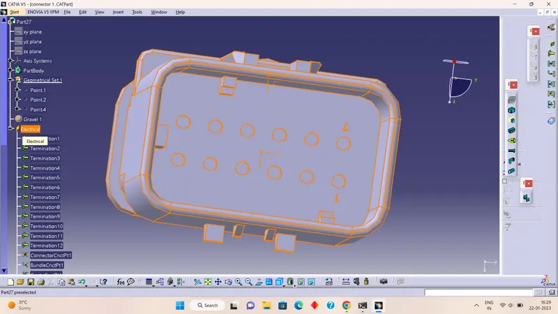
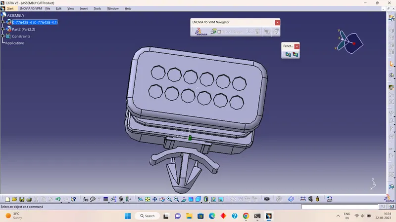
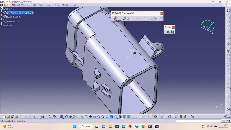
We have added both 12-pole interconnection connectors and 8-pole connectors inside the tailgate harness geometrical bundle assembly.
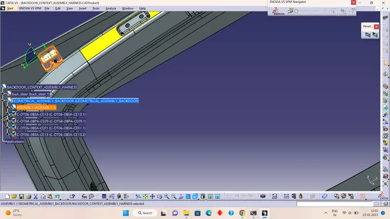
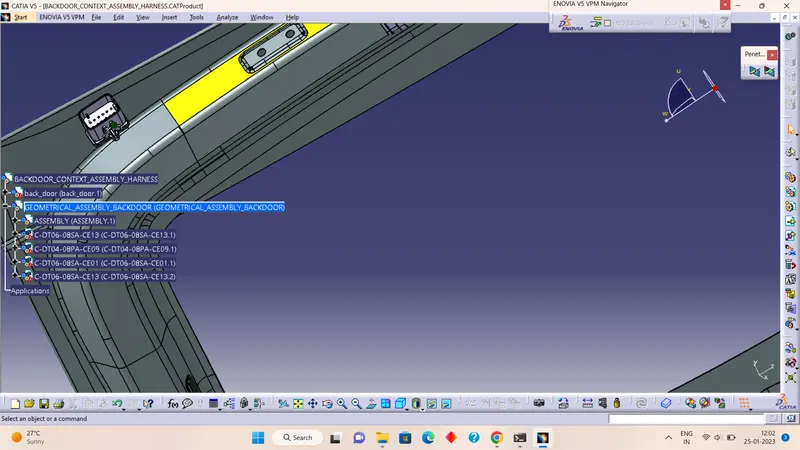
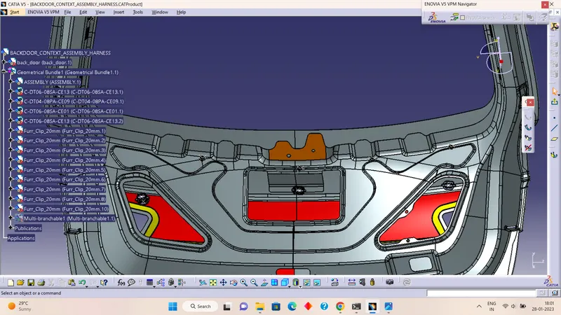
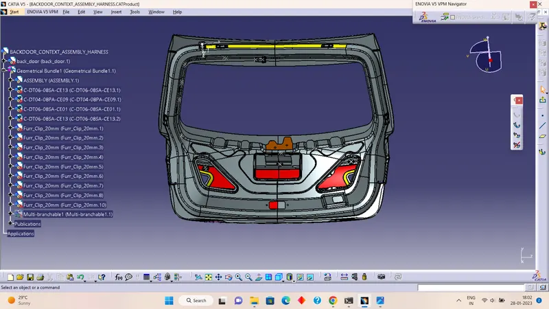
• We have used commands like manipulation, compass, snap, and smart move to place all 5 connectors in their desired location.
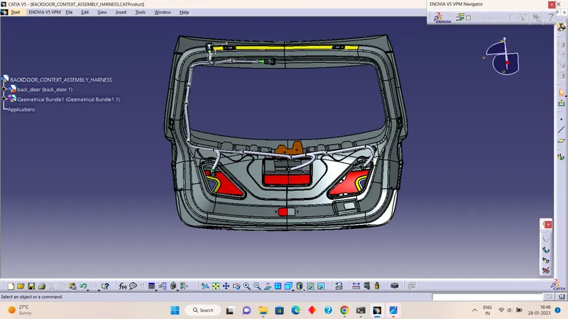
• We have placed all the connectors in their desired position as shown in the below figures.
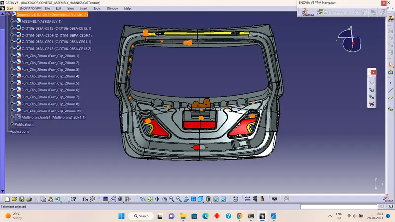
Also, we have used furr tree clips for our harnessing of door
Placing fir tree clips to the required locations to ensure proper harness routing throughout the Assembly.
- Ensure no fouling of harness to the back door sheet metal components.
- Enough clamps shall be provided to ensure positive clearance with the surroundings and the safety of the wiring harness. The distance between two clamps/clips on a straight branch should be a maximum of 200mm. However clamping requirements should be decided based on the harness bending and mounting arrangements.
4. - Wiring Harness Routing
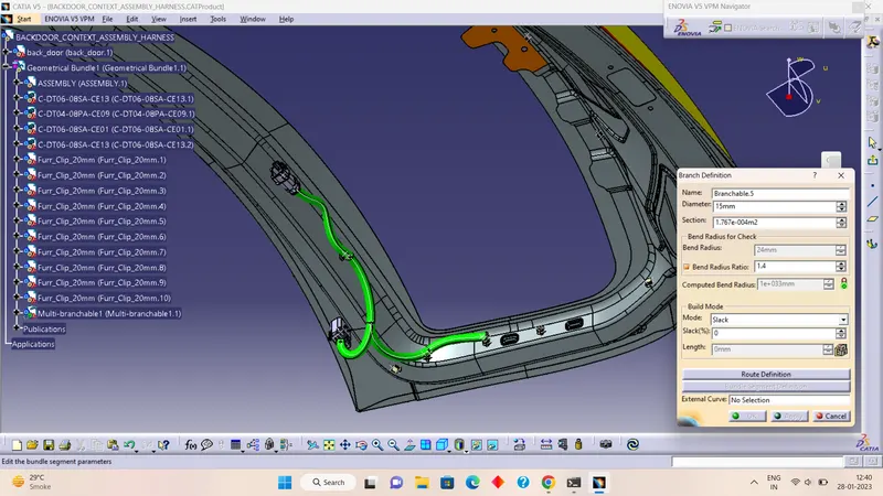
Before, bundle routing we have to make a curve by creating points in hollow parts of the given tailgate.
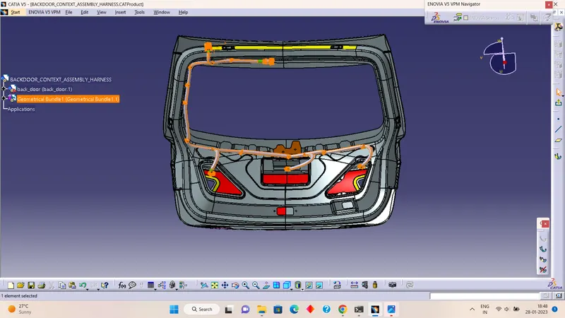
- Now, the car tailgate assembly is ready for the bundle routing as shown below image.
- Also, we have activated harness assembly as a geometrical bundle.
- The diameter of the bundle leading to 2 tail lights is 15mm and the number plate light is 15mm respectively.
- The bend ratio is assumed to be 1.4 with some of them being different as per our requirements and appropriate slack between 1-10% is given wherever needed.
- We have created branch points, from the main branch to both tailgate lights and number plate lights.
- First, we have started bundle routing from the interconnection connector to the nearest Mounting clip available and continue to add multibranchabe bundles to achieve the required harness bundle. The main bundle harness diameter is considered 15mm.
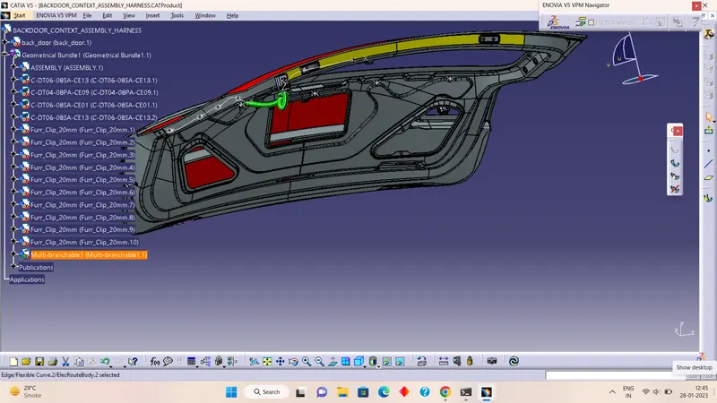
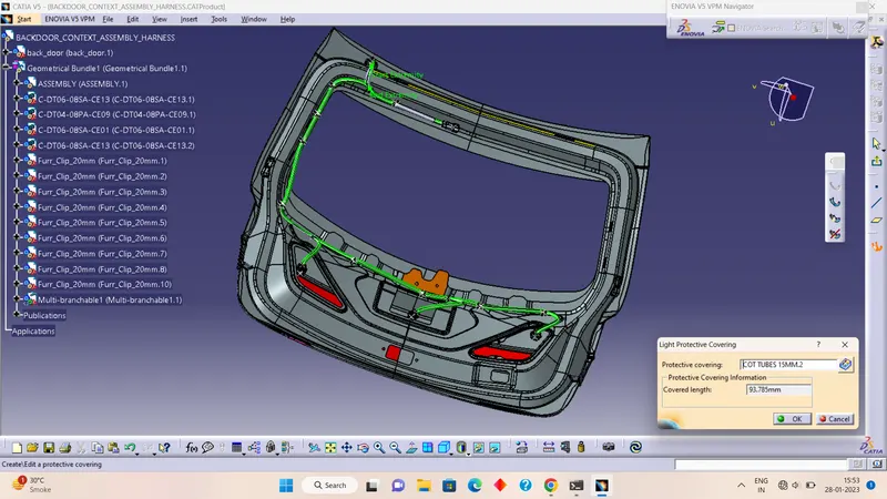
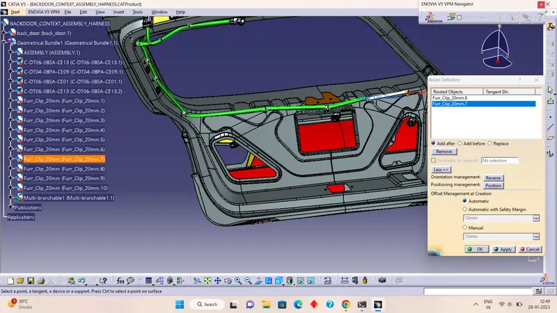
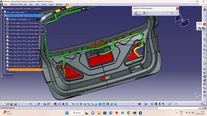
5. Applying Protective Cover
After bundle routing, we have to add a protective covering to the harness bundle so that it will get protected from damage.
- Harness bundle should be protected with a flexible rubber cover at the interconnection region where it is a critical place and subjected to opening and closing of the door. There are more possibilities to damage the wiring harness if no proper protection coverage is provided.
- Corrugated conduits and protective hoses with various properties, from heat resistance through abrasion protection and impact strength to noise reduction, protect valuable cables against all unfavorable external influences.
- Slit COT tubes are provided for protecting the harness from physical and other environmental damages that can occur in the long run.
- Start or End Extremities at the Connector bundle entry side should be given a gap of 30mm
- Selection of corrugated tubes is mainly driven by the wiring harness bundle diameter and temperature resistance requirements.
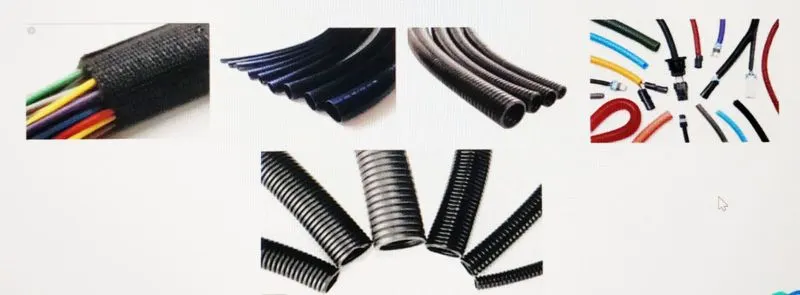
- After bundle routing, we have to add a protective covering to the harness bundle so that it will get protected from damage.
- Here, we have used PVC tape for the current harness assembly.
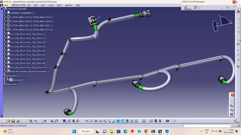
- We have given start and end extremities wherever needed for the PVC tape as shown below image.
- Setting end and start extremity of covering has been set for 30mm.
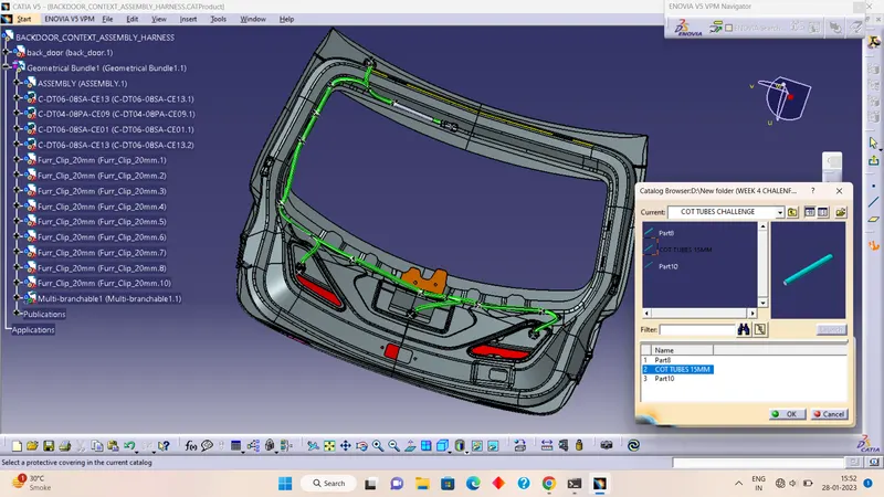
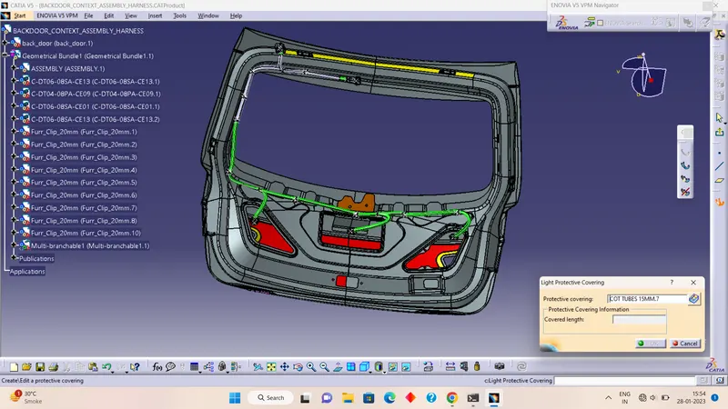
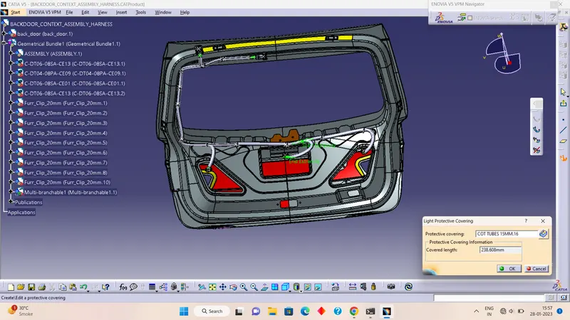
6. Checking bundle continuity.:-
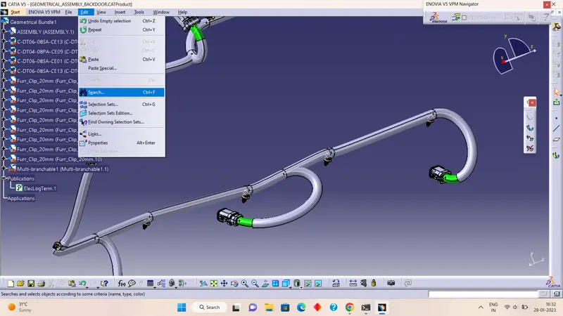
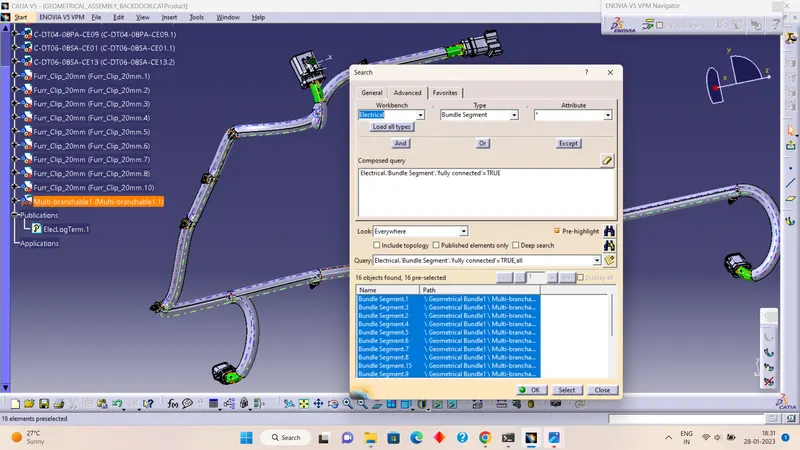
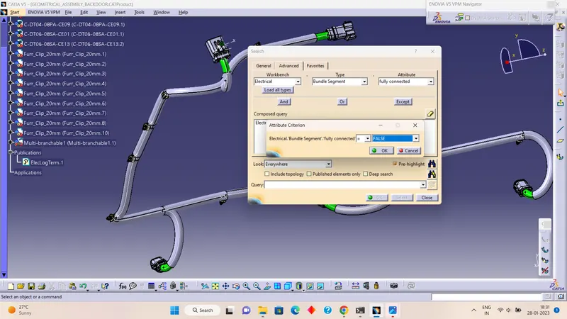
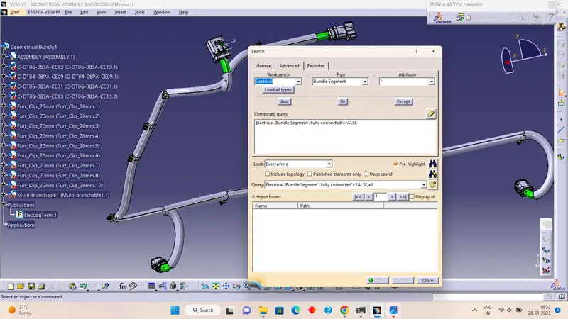
- First, we have to select multi-breathable and go through the sequence as Edit>Search>Advanced>Workbench Electrical Type-Bundle Segment>Attribute-Fully Connected.
- After selecting the 'True' condition will show all the connected bundle segments while selecting the 'False' condition will show all the non-connected bundle segments.
- Here, we have selected the 'True' condition and searched for the results. All the bundle segments are highlighted and showing that all the bundle segments are connected electrically as shown in the below image
7. Create flatten view of the wiring harness bundle:-
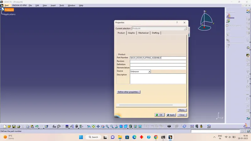
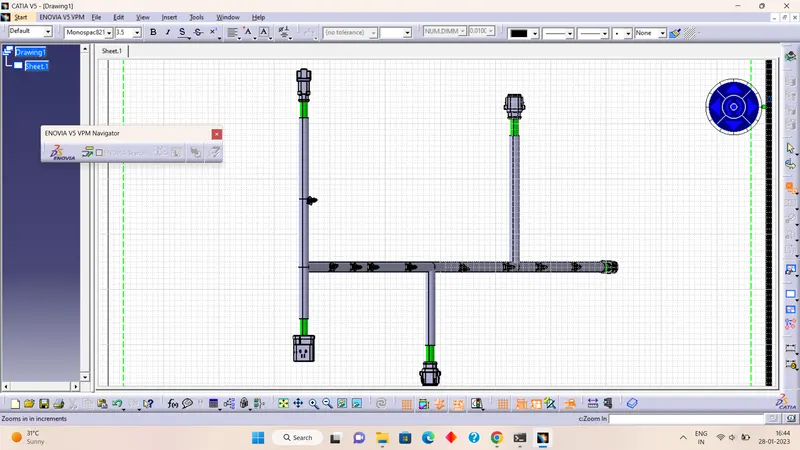
- To create a flattened view of the harness assembly, we have to work on the Electrical Harness Flattening workbench in CATIA V5.
- Also, we have to make sure that the flattening file is saved into the same folder where we have all the parts of the harness assembly.
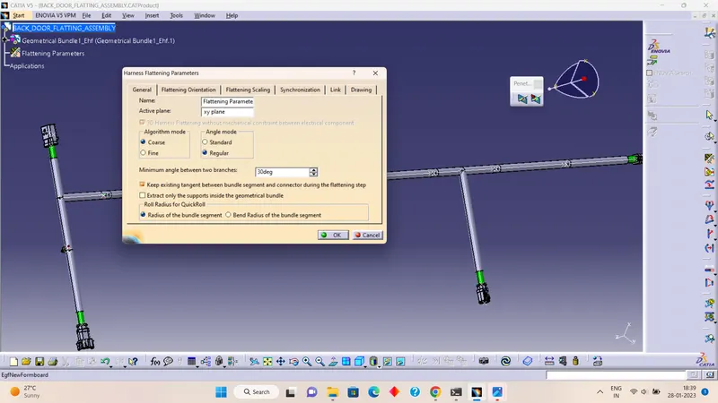
- As shown in the below image, while defining the wiring harness flattening parameters make sure to select a Single line for the bundle segment and a Double line for protective covering. After that, we have to extract and bring the bundle assembly into the car tailgate flattening product file.
- To flatten the harness assembly, we have selected Face as an active plane and selected all the branches as shown in the below image.
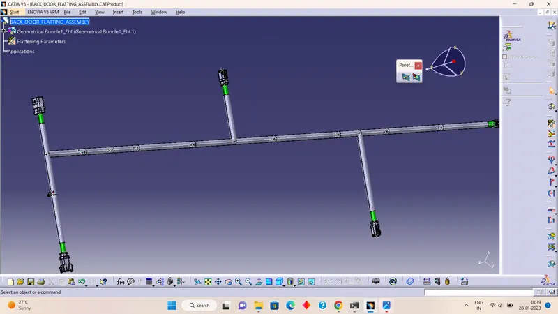
- After creating flatten view, we have to rotate the connectors and clips in the right direction along the selected plane using manipulation commands.
- we have to design the flattened view by using features like roll, rotate,....options are there to use those commands we perform those operations.
8. Creating a drawing view for a given flattened product:-
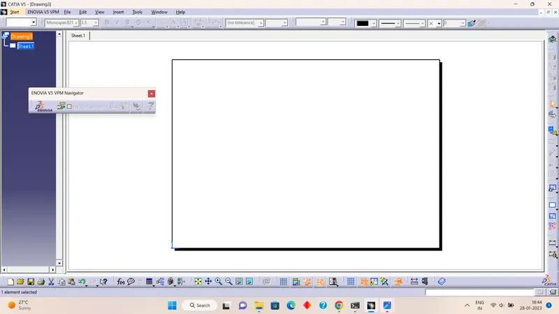
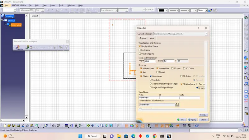
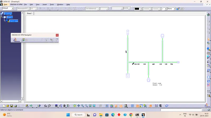
- As shown below image, we have to insert the front view of the harness assembly into the drawing file and define the drawing properties
- It should be noted that for the Dress-up feature 3D wireframe is always ON. If this setting is not selected then the bundle segments will not be visible on the drawing view.
Conclusion:
Routing of the wiring harness for the car tailgate assembly has been done and prepared flatten-view drawing in CATIA V5. Applied all the packaging rules while routing the wiring harness, and implemented industry best practices in the harness design. Also, provided details like clearance, clipping selection, harness fixing requirements, and harness continuity to design the harness.