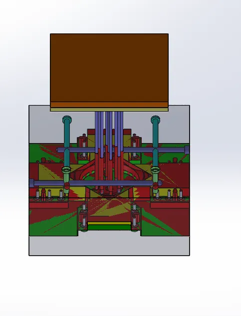
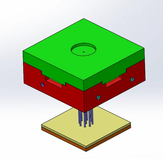
Project 2
CPU _FAN_CASE
Procedure for Cpu_Fan_Case
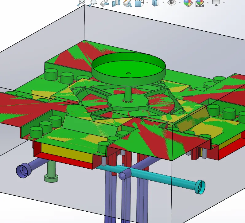
- Step -1: - To design the core & cavity of the Cpu-Fan-Case
- Step -2: - After completing the component select the material in my case, I am taking the material as ABS and it's having a shrinkage of 0.6% (1.006) component size to be increased by using the SCALE command in mold tools.
- Step – 3: - Check the Draft analysis of the component and also finalize the tooling direction for the core and cavity of the mold block. Draft analysis is mainly used for the component and to avoid the difficulty of ejecting the component.
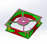
- Step -4: - If the Draft Analysis is ok then go for the parting line command in the mold tools command bar. It is the line that separating core and Cavity blocks. If any hollow sections are present in the component use the shutoff surface command in mold –Tool Bar then Core and Cavity surfaces are formed.
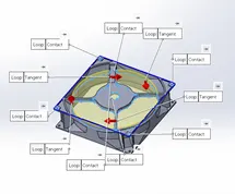
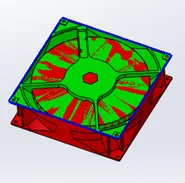
- Step -5: -Next is to create a Parting surface for the component for that use Ruled surface command in the surface toolbar in the ruled surface use Sweep option to form the surface and select the direction and select the face and enter the value of 300mm per side and repeat the same for side of the component.
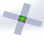
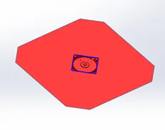
- Step -6: -then use the Loft surface for connecting the surface with radius and Kint the surface and use the copy/Move command in the Direct Editing Tool bar and make a copy of the final parting surface and add with the Core and Cavity surfaces.

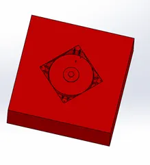
- Step -7: -Then open the assembly file to create new documents and save the file .and insert 2new part files and name it as Core steel & Cavity steel and Save the parts. Then adjust the sprue location for the component and assembly for the mold creation.
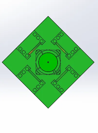
- Step -8: -Edit the core steel part file start sketching on the Top Plane and draw the Rectangle with the dimension of 300mm x 300mm and extrude the sketch with 80mm for both sides and offset the core surface and use surface cut command and trim the surface and repeat the same process for the cavity block at final we get the core and cavity blocks
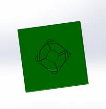
Procedure for creating Slider and Washers and Locking system
- Step -9: - for the CPU fan case component having more features on the side that cannot be clear in the Core and cavity parts that we need to add a slider for that features. to create sliders create a sketch in the top of the core and create a plane with the component face as a reference and use the split command and select the sketch and plane and use cut bodies and select ok then the slider features are formed
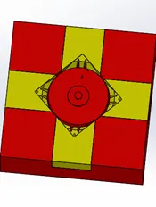
- Step -10: - then after start editing the slider body to create wedge and guideways for the slider to create wedge start sketching on the side face of the component and keep the wedge angle as 300and ¾ of the height of the slider and add the 5mm sketch on the bottom face with connecting the wedge of the slider and save the slider separately
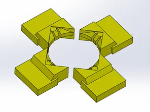
- Step -11: - import the slider and separate from the core and cavity blocks the final core and cavity blocks are formed with slider to add the slider insert an assembly file and name as CPU Fan Case Slider and import all the slider file in the assembly.
- Step -12: -insert new Part file and name as Washers and select the face of the guideways face and Start a sketch on that face and divide the take a 16mm sketch and make 3 sketches on the face and extrude 3mm of the sketches use the mirror command to copy the same sketch on the other side of the component and add the 6mm circle and extrude up to 22mm in downwards direction and at the to make 11 mm circle and extrude up to 7mm and use the sketch with pattern and form the washers for the mold.
- Step -13: -After creating the washers insert the holes for the code block by using the hole wizard command .for the cavity blocks use extrude cut command to create relief for the component.
- Step -14: - to add the washer edit the core block and extend the guideways part and start sketching on that face
-
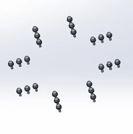
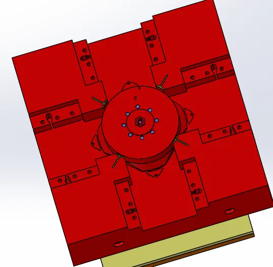
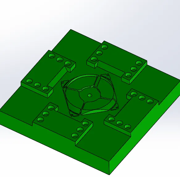
- Step -15: -To add the locking machines edit the core block and create the sketch and add the lock feature and use extrude cut up to the slide base and also edit the slider block and make a hole with 3mm and use extrude cut up to the slide base and the distance between the pin slot and lock set is 45mm
-
Procedure for Plastic Knob Ejection system with Ejector pins and Plates, Runner and Gate system, Air vents and Cooling
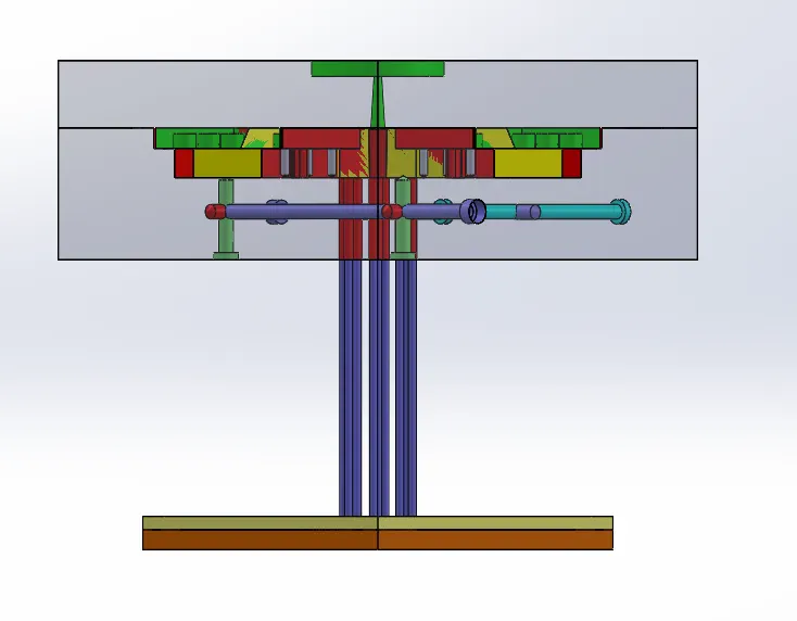
- Step -16: -Ejection system with Ejection Pins and Plates Ejection system is mainly used in ejection the component after the molten material fills the core and cavity to remove the final component the main components are Ejection pins, Ejection plats which connects the ejections pins, and ejection system,
- Step -17: -Ejection pins for this component I am using 6mm ejection pins but mainly there are 2 types of pins are used they are 3mm &6mm pins mainly used it will change to the system to system and company to the company also. For creating the ejection pins I took the previous reference plane and start sketching on the plane. Sketch’s the pin dia 6mm where ever it required and extended up to 250mm and make the surface is the starting point and ends with 250mm length and in the of the pin are circular position there is no change in the pinhead dia 10mm and the thickness 3mm. and coming to the relief for the pins and pinheads for the pin relief as the 6.94mm and 12mm
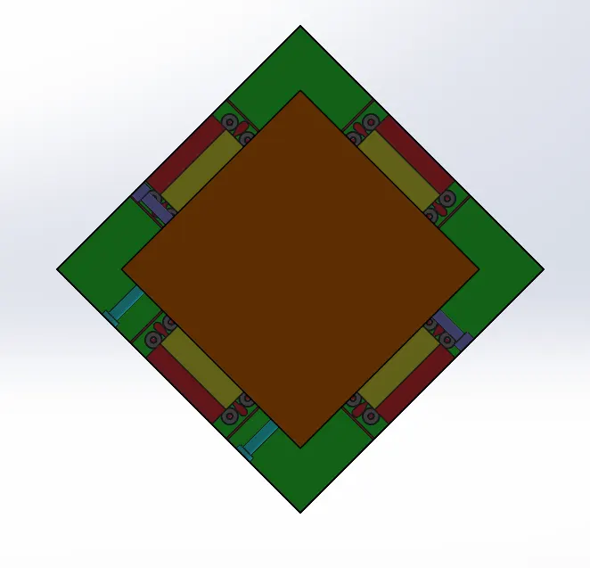
- Step -18: -Draw the rec sketch at the top for ejecting pin plates with less than 45mm on the width of the core. And extrude the sketch up to 10mm below the sketch surface and create another sketch for the component and extrude 15mm above the pins guider and add the relief for the pins on the first plat and is 2mm.
- Step -19: -The next step is to create a runner and gate and spur for the component for start creating runner start sketching on cavity block on the top face as reference dia 100mm and the depth of cut is 12mm for the material injection slot and at the end of the runner sump and draw the 5.8mm circle and by using extrude cut option give the draft angle for the component is 3.50angle outside from the circle. And cut spur up to the end of the Cavity block. And also add the 5mm depth cut on the core block. Then the runner is completed.
- Step -20: -And start designing for the spur for that draw a line on the and use the extrude command and select the midplane and of depth 4mm and width of 4.75mm and add the gateway for the component add the sketch for the spur with the tapered triangle of 1.5mm and 8mm and extend to0.5mm and add Draft to the lower face of the spur. And the draft of 400.and trim the unwanted extra parts for the gate and combine the gate and spur and subtract the from the core block. Remove unwanted extra features in the core block.
- Step -21: -The next step is to create the Air vents in the core block it is useful to remove the unwanted air gaps in the core and cavity blocks. And its use for free ejection and molding of the component. For the draw a sketch on the core face and make an offset of the end line of the component with 2mm and extrude the component on both sides and split the component with the core face and make a face offset of 1mm and add fillets for it and repeat the same steps for the attachment with 0.5 mm and add fillets and combine and separate from the core block
- Step -22: -The next step is to create the cooling system for the mold it plays an important role in the mold design for solidification of the mold for easy ejection of the mold. For that, we can use as hole wizard command in the features command prompt and use the M10 hole with18mm head with the required lengths in my case I am using the series type cooling system to connect all the pipes around the mole cavity with a specific distance.
This is the process of creating an ejection system with ejector pins and plates, runner and gate system, air vents, and cooling channels for the mold