Project 2
Develop general arrangement for the RC office building. Analyze and design the building as per IS standard code in TEKLA STRUCTURAL DESIGNER. Refer the attached plan and elevation. The building to be designed for dead, live, wind and seismic loading.
Report of each member to be generated and extract drawings for structural plans, beam reinforcement details from the software
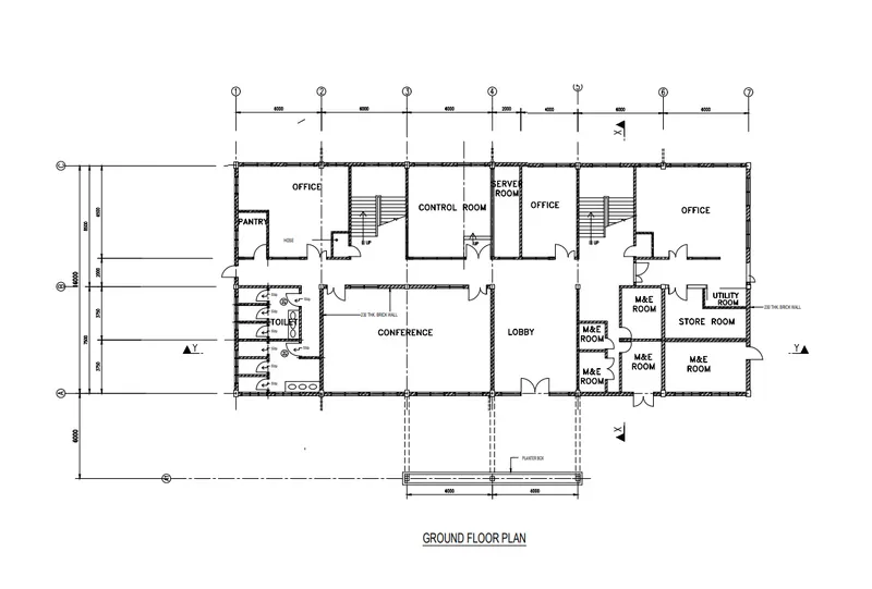
GROUND FLOOR PLAN
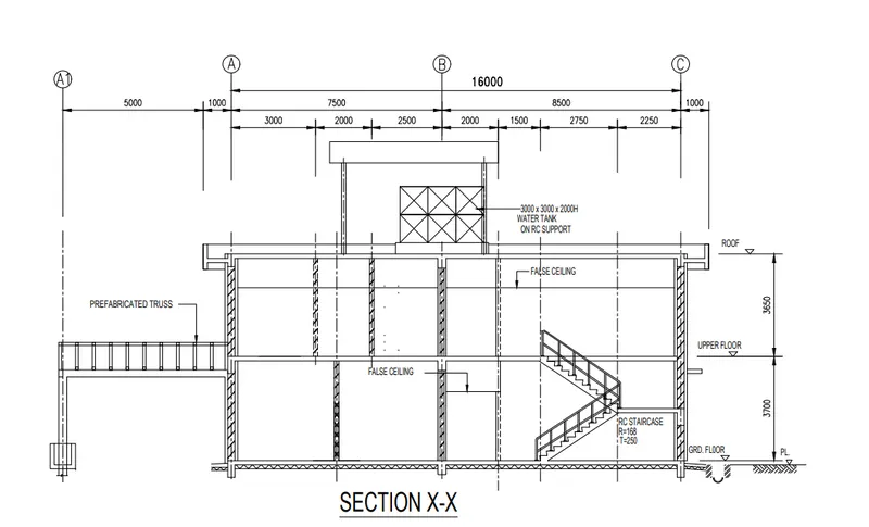
SEC X-X
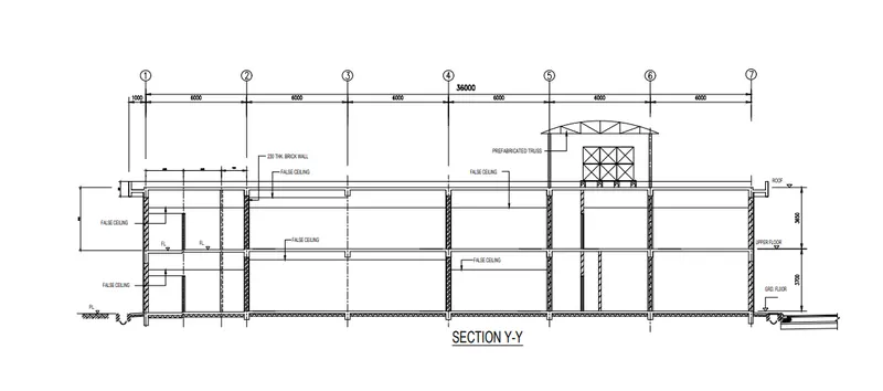
SEC Y-Y
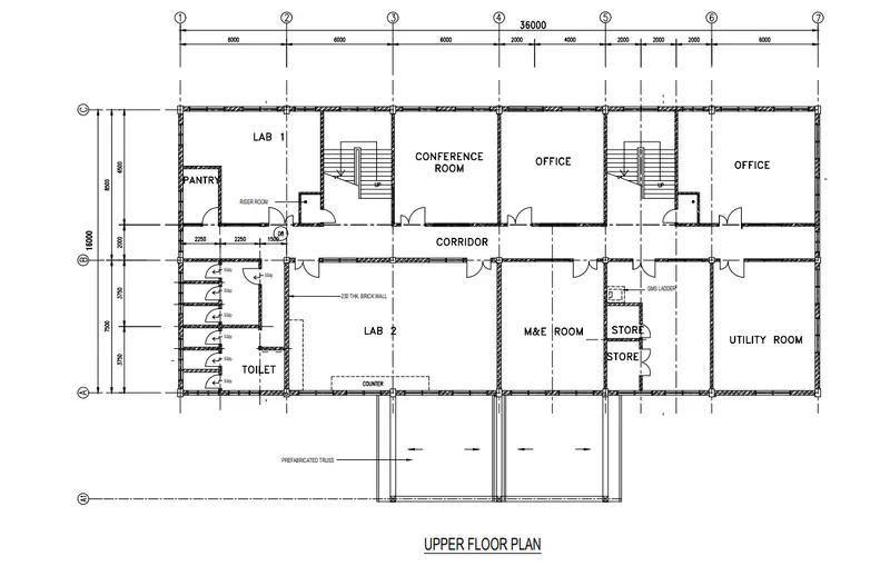
UPPER FLOOR PLAN
PROCEDURE:
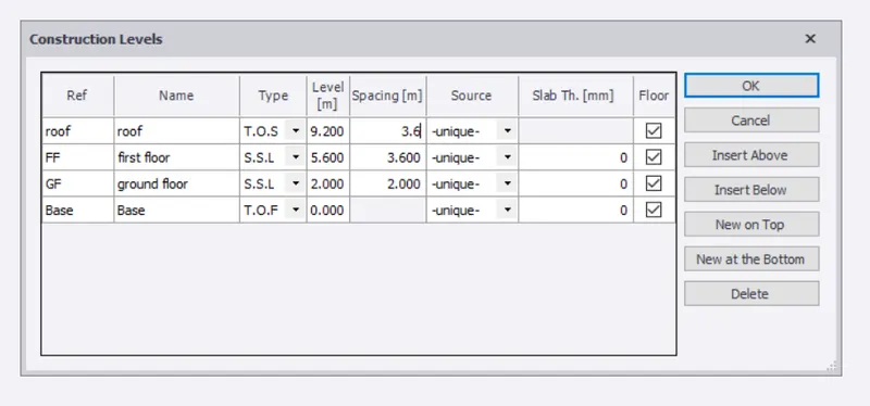
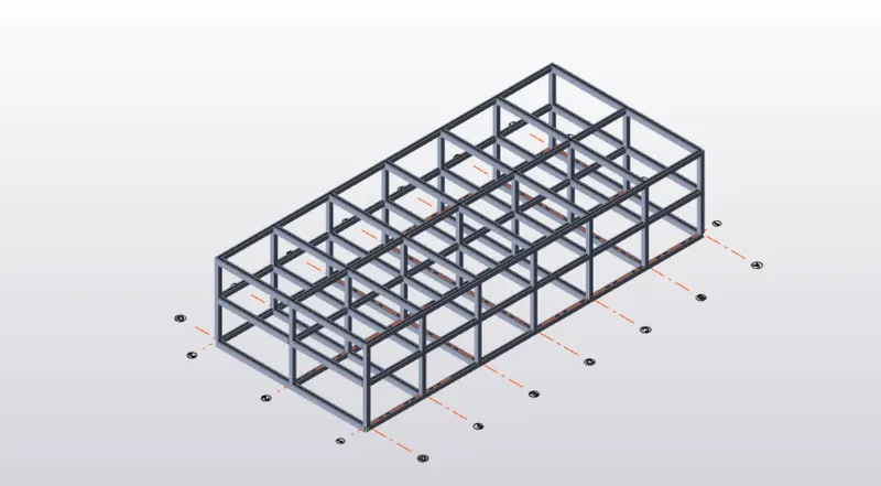
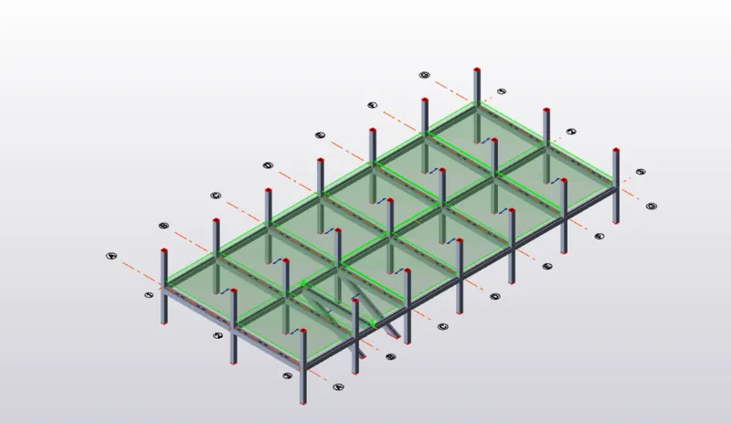
open a new file in tekla and enter the floor settings as shown below.
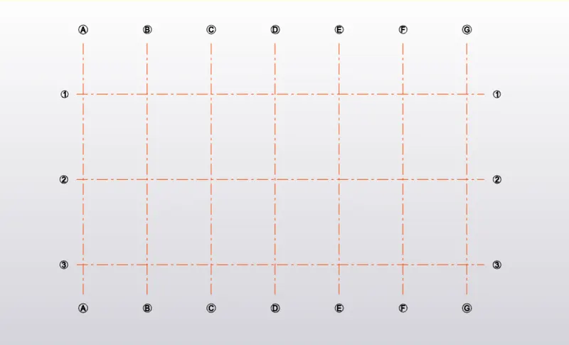
now go to model from ribbon and draw the grid lines taking the reference of plan given.
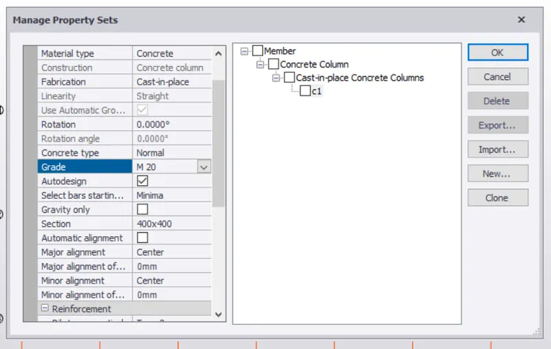
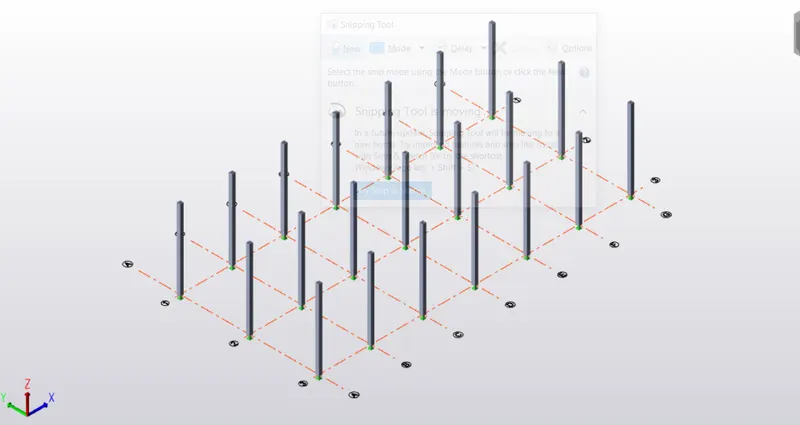
now go to manage property sets, select a new member and define a new column and enter its properties.
now place these columns at the grid intersections.
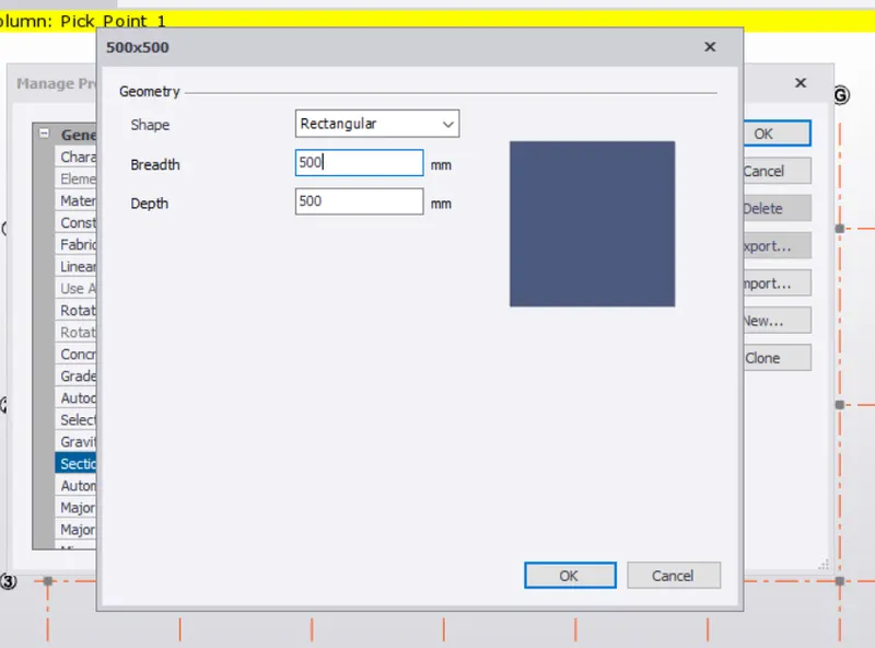
in the same way define the beams and enter its dimensions.
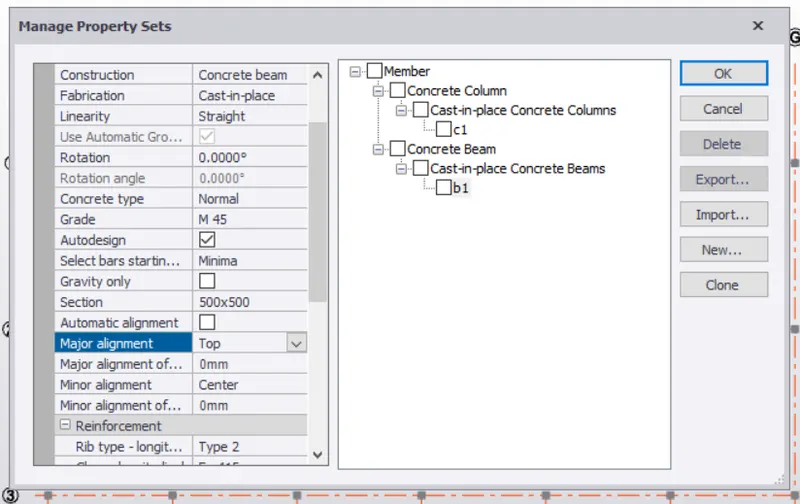
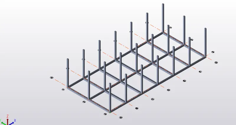
place these beams connecting the columns at ground floor.
complete the model by drawing beams in between columns.
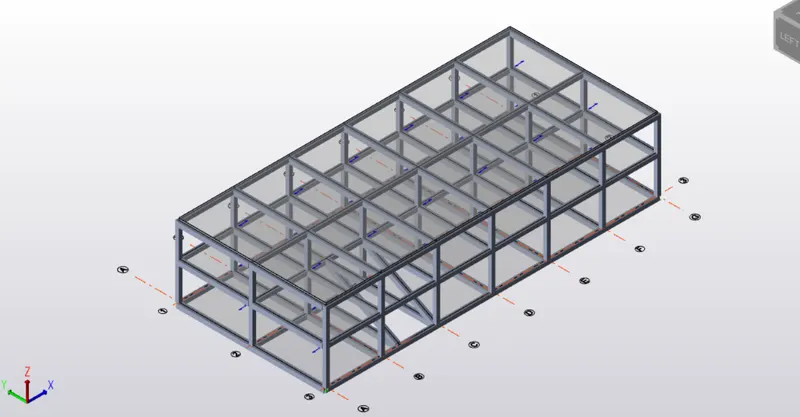
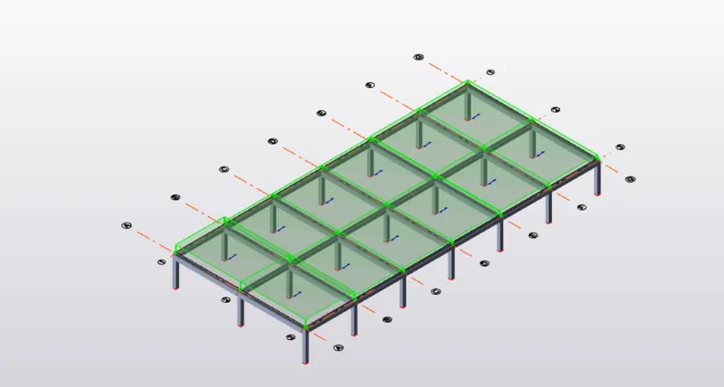
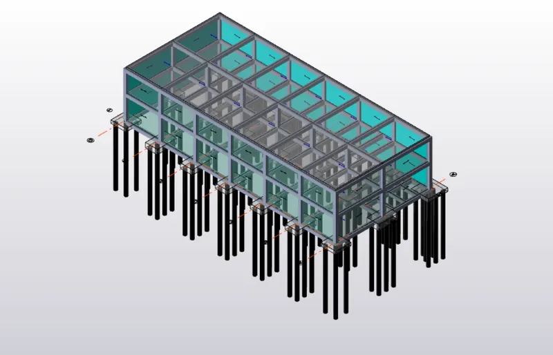
now define the slabs and place them in the model.
model a staircase in the model by making a rectangular portion as substructure and drawing inclined beams
with a slab in between them.
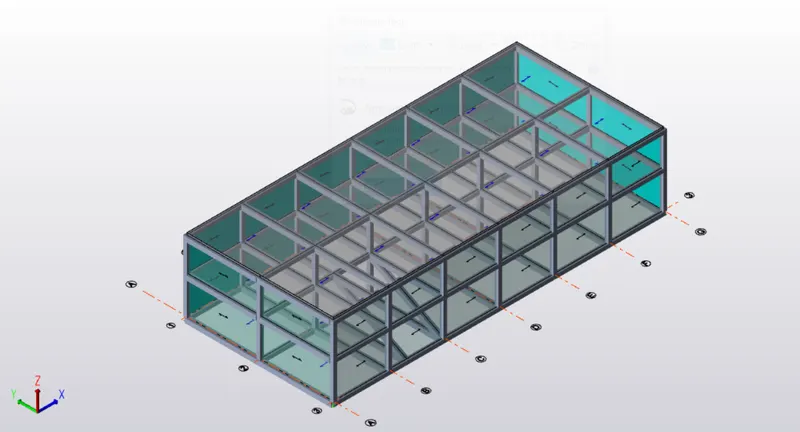
DEAD LOAD :
self weight of slab ( software )
finish load = 0.01 * 25 = 0.25 kn/m3
brickwall load = wall thickness * unit weight of brick * height ( Gf to roof )
= 0.15 * 18 * 3.6
= 9.72 kn/m3
service load = 0.3 kn/m2
apply a dead load of 0.25kn/m3 on all the slabs and service load of 0.3kn/m2.
apply a brickwall load of 9.72 kn/m3 on all the interior and exterior beams of ground and first floor.
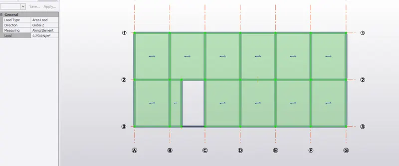
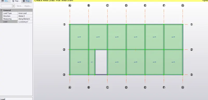
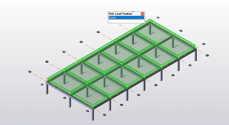
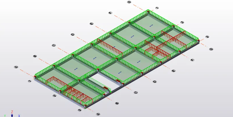
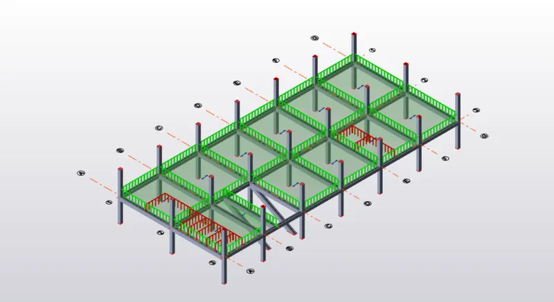
LIVE LOAD :
STORE ROOM = 5 KN/M2
STAIRCASE = 5KN/M2
OFFICE = 3KN/M2
REST ROOM = 2KN/M2
MEETING ROOM = 2KN/M2
TOILET = 2KN/M2
PANTRY = 3KN/M2
CORRIDOR = 4KN/M2
apply these live loads on the slabs of all the floors.
WIND LOAD CALCULATIONS :
Vz = Vb * k1 * k2 *k3 *k4
Vz = 39 * 1 * 1.05 * 1 *1
Vz = 40.95 m/s
Pz = 0.6 Vz ^ 2
Pz = 0.6 * 40.95^2
Pz = 1.06 Kn/m
h = 7.7m w = 16m l = 36m
h/w = 0.48 l/w = 2.25
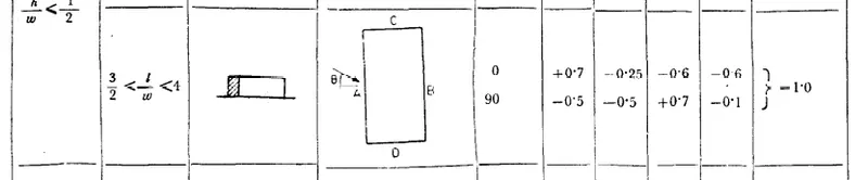
along face A,
+cpe -cpe
external pressure cofficient 0.7 0.7
internal pressure cofficient 0.5 -0.5
pressure coefficient 0.2 1.2
wind pressure 1.06 1.06
load to be applied 0.212kn/m 1.272kn/m
along face B,
+cpe -cpe
external pressure cofficient -0.25 -0.25
internal pressure cofficient 0.5 -0.5
pressure coefficient -0.75 0.25
wind pressure 1.06 1.06
load to be applied -0.795 kn/m 0.265 kn/m
along face C and D
+cpe -cpe
external pressure cofficient -0.6 -0.6
internal pressure cofficient 0.5 -0.5
pressure coefficient -1.1 -0.1
wind pressure 1.06 1.06
load to be applied -1.166kn/m -0.106kn/m
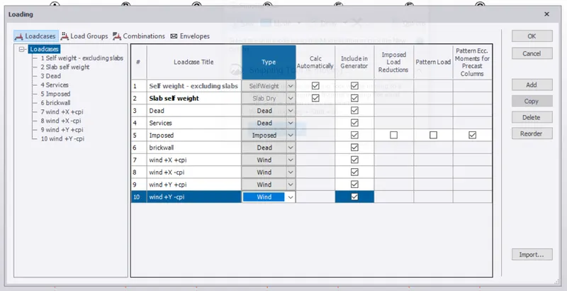
now apply these loads on all the faces of model.
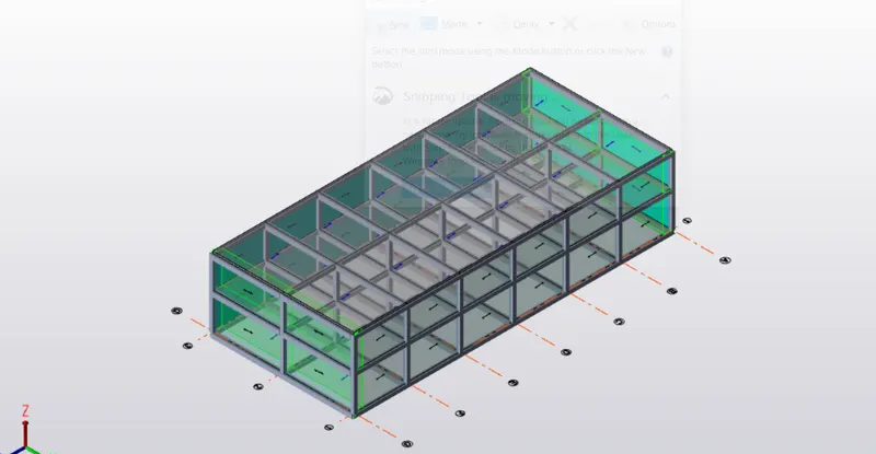
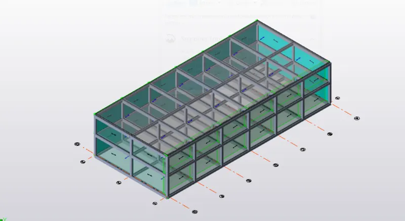
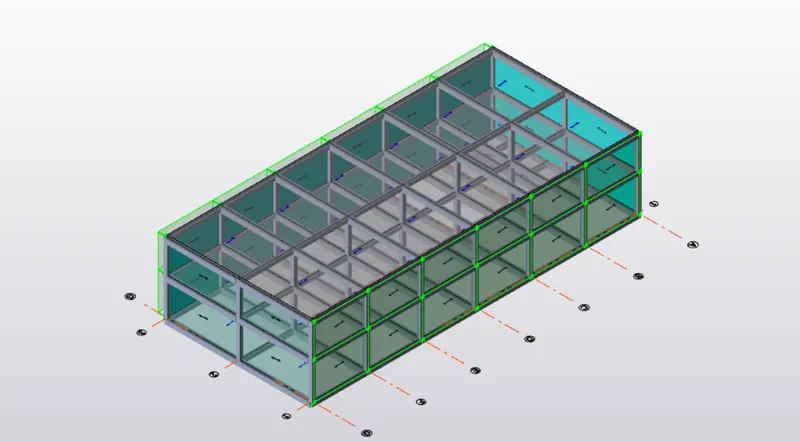
ROOF LOADING :
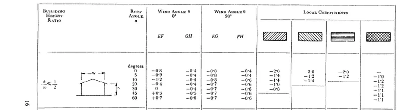
EF GH
external pressure cofficient -0.8 -0.4
internal pressure cofficient 0.5 -0.5
pressure coefficient -1.3 0.1
wind pressure 1.06 1.06
load to be applied -1.378KN/M 0.106KN/M
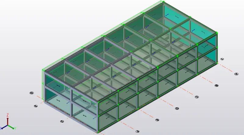
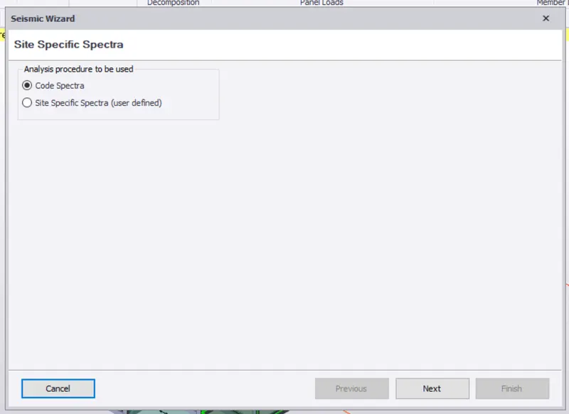
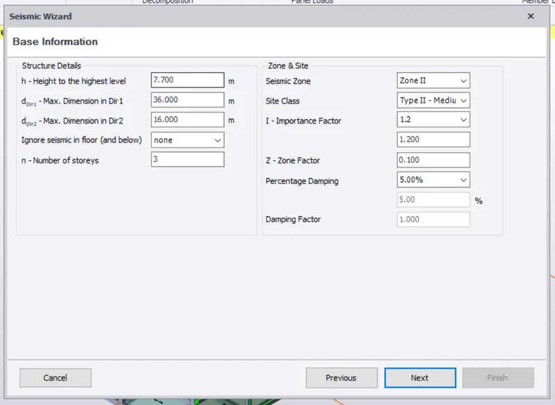
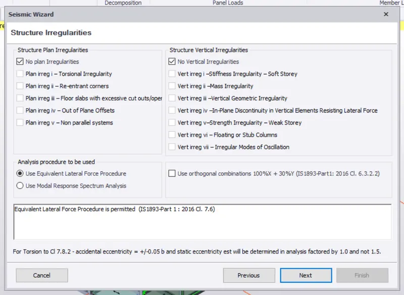
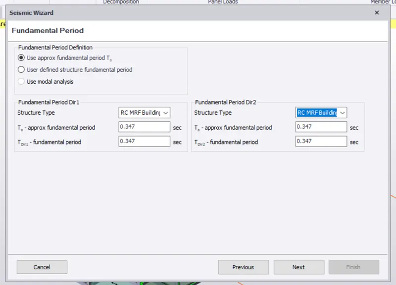
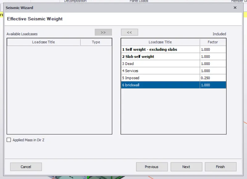
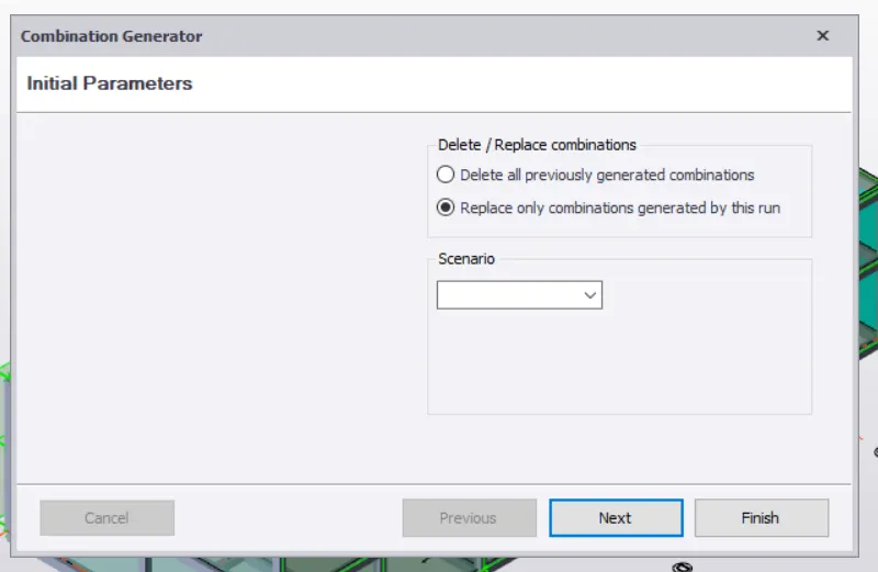
now apply seismic load to the model following the procedure below.
now check the model for shear force, bending moment diagram and axial force.
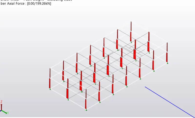
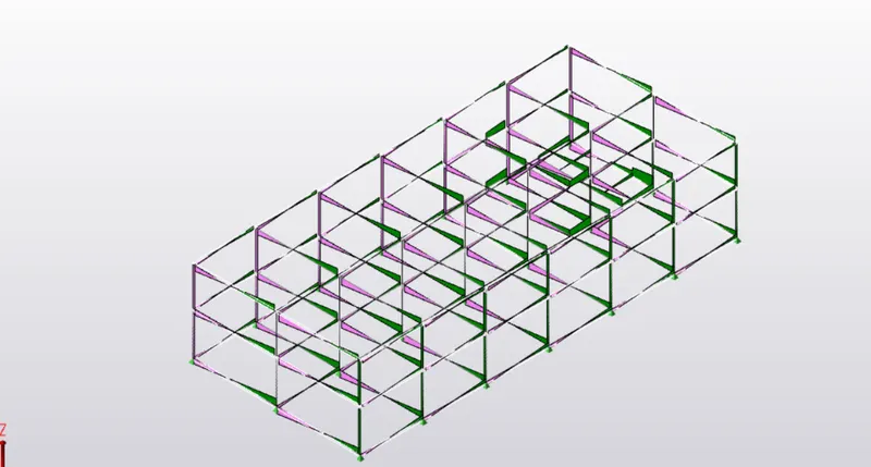
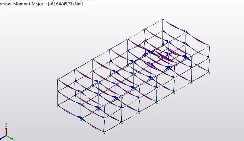
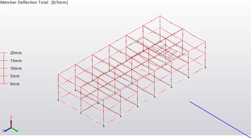
now click each member ,right click and design the member ,remove the failures.
review the model until it passes or shows warning.
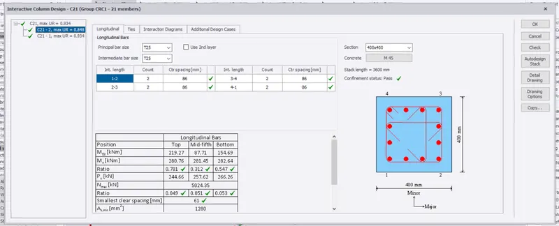
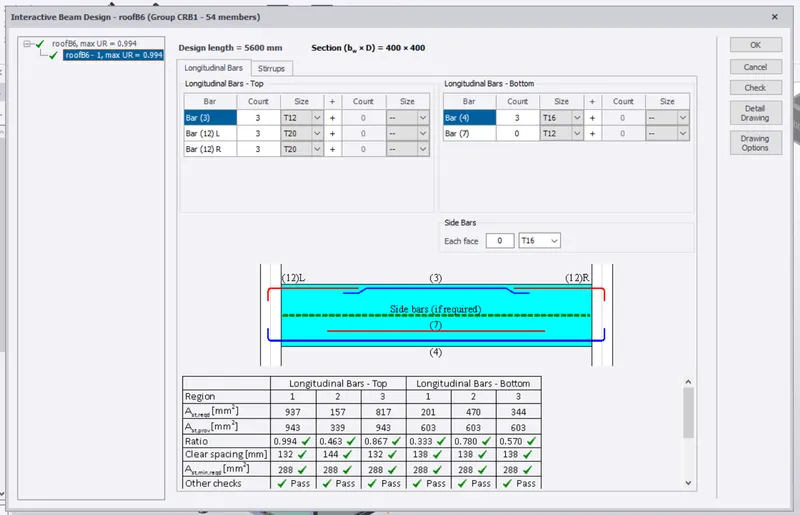
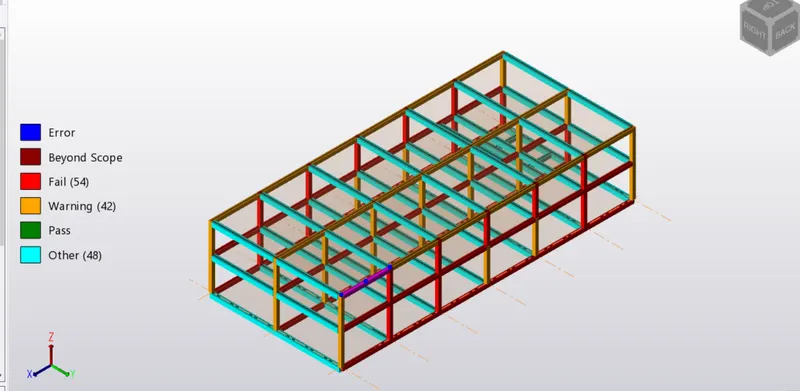
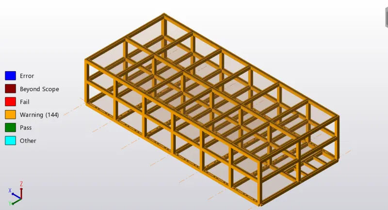
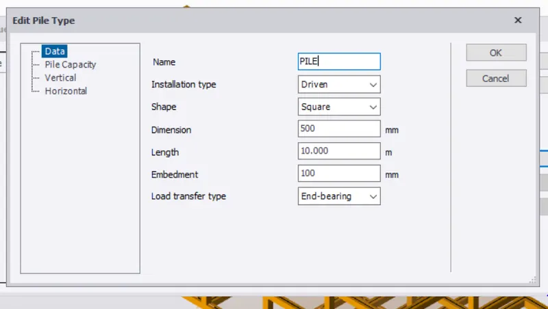
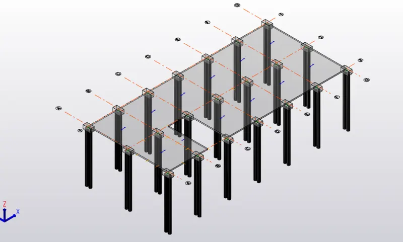
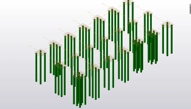
now to design the foundation, go to design select settings and select foundation, give the input parameters.
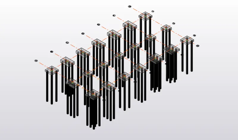
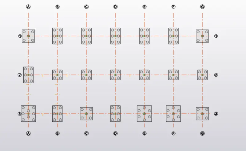
go to pile caps and draw it at the base of the model.
after drawing right click and design the member .
check for failures and correct them.
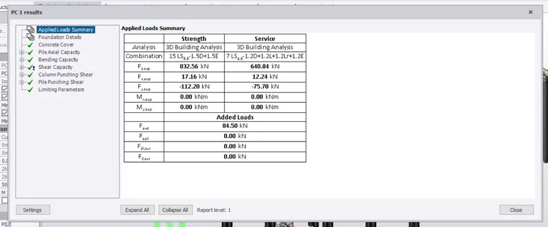
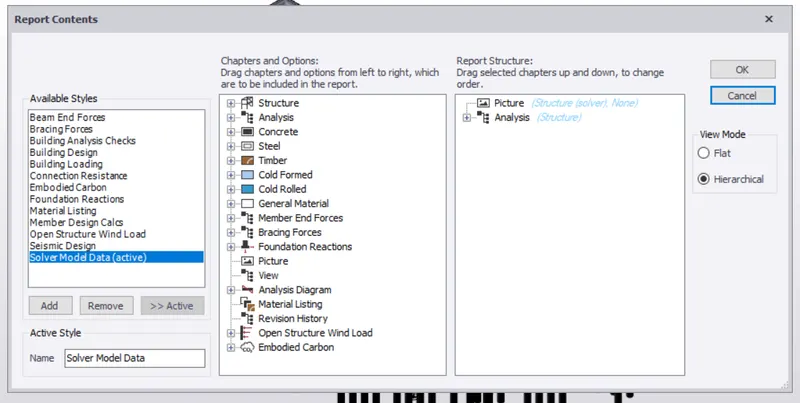
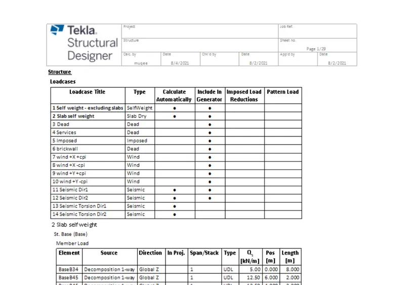
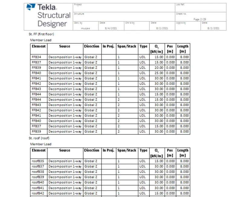
now to obtain the report, go to report select model report and select the load cases, combinations.
obtain the report of load cases and combinations of the model.
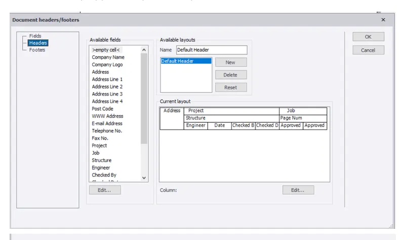
with the help of edit header we can make changes in the name settings of the project.
validate the model.