Project 2
| PROJECT - 2 |
AIM : To find maximum heat generation of the battery & SOC of the battery at 2*104 seconds of the battery operation.
GIVEN :
Battery Resistance = 0.0005 `Omega`
Delta Time = 0.1
Entropic Factor = 2.
| Time | Time Step | Battery Current |
| 00:00.4 | 0.1 | -0.9632 |
| 00:00.5 | 0.2 | -0.952 |
| 00:00.6 | 0.3 | -0.9072 |
| 00:00.7 | 0.4 | -0.9632 |
| 00:00.8 | 0.5 | -1.0304 |
| 00:00.9 | 0.6 | -0.9632 |
| 00:01.0 | 0.7 | -1.0304 |
| 00:01.1 | 0.8 | -1.008 |
| 00:01.2 | 0.9 | -0.9856 |
| 00:01.3 | 1 | -0.9632 |
| 00:01.4 | 1.1 | -0.9184 |
| 00:01.5 | 1.2 | -0.9296 |
| 00:01.6 | 1.3 | -0.9296 |
| 00:01.7 | 1.4 | -0.9296 |
| 00:01.8 | 1.5 | -0.9184 |
| 00:01.9 | 1.6 | -0.9408 |
| 00:02.0 | 1.7 | -0.896 |
| 00:02.1 | 1.8 | -0.9072 |
| 00:02.2 | 1.9 | -0.9072 |
| 00:02.3 | 2 | -0.9408 |
| 00:02.4 | 2.1 | -0.9296 |
| 00:02.5 | 2.2 | -0.9296 |
| 00:02.6 | 2.3 | -0.9968 |
| 00:02.7 | 2.4 | -0.9968 |
| 00:02.8 | 2.5 | -0.9408 |
| 00:02.9 | 2.6 | -0.9408 |
THEORY :
- Heat Generation in Battery.
There are two sources of heat generation in a battery -
|
1. Joule Heat : |
It is the physical effect by which the passing of current through an electrical conductor produces thermal energy. Also called resistive heating, ohmic heating.
|
||||
|
2. Entropic Heat : |
It is the rate of change of battery's open circuit voltage wrt. temperature.. It is a function of temperature and SOC. For this model purpose it is considered as a factor of 2 to Joule Heat. |
| `therefore\ \Heat\ \Gen\erated = Jou\l\e\ \Heat + Entro\p\ic\ \Heat` |
- State Of Charge (SOC) of Battery.
It is defined as the ratio of the available capacity Q(t) and the maximum possible charge that can be stored in a battery.
| `SOC = (Q_t)/(Q_m)` |
A Simulink model is made for SOC measurement : -
Blocks Used-
|
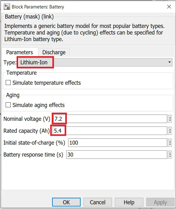
1 . Battery |
It implements a generic battery block for most popular battery types.
|
||
|
2. Bus Selector |
- This blocks accepts a bus as input and outputs the elements selected by user separately. - In this model Measurement Bus from battery is taken and connected with scope for 2 elements viz. SOC & Current. |
||
|
3. Controlled Current Source |
- It converts its input signal into an equivalent current source. - The current generated is driven by the input signal of the block. |
||
|
4. From Workspace |
- It is used to read data from MATLAB workspace. - In MATLAB workspace data is imported from excel sheet. |
||
|
5. Powergui |
- It sets the simulation type, simulation parameters and preferences. - For this model continuous simulation type is selected. |
SIMULINK MODEL :
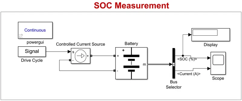 |
- In this model, A drive cycle source/signal is connected to battery via a Controlled Current Source block to control the current via the battery according to the input cycle.
- Output from battery is given to bus selector and then to scope and display.
- The model is run for 208 seconds to measure SOC.
OBSERVATIONS :
- Max Heat Generated:-
Max Battery Current = -0.896
Time = 2 min = 120 seconds.
Joule Heat = `I^2*R*t` = `(-0.896)^2*0.0005*120 = 0.04816\ \kJ`
Entropic Heat = 2*(Joule Heat) = 0.09632 kJ
Total Heat Generated = Joule Heat + Entropic Heat
= 0.04816 + 0.09632
Max Heat Generated = 0.14448 kJ
- SOC Measurement:-
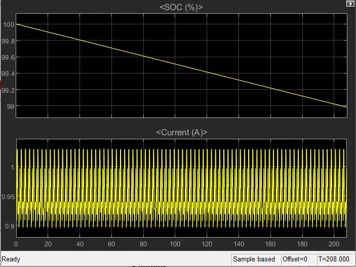 |
SOC = 98.98 %
|
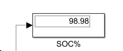
- When the model was run for 208 seconds, the SOC is 98.98 %.
CONCLUSION :
Maximum Heat Generated for the given drive cycle is 0.14448 kJ.
Battery SOC at 208 seconds for the given drive cycle is 98.98%.
----------------------------------------------------------------------------------------------------------------------------------