Project 2
Model & Design a Proposed PEB Warehouse using STAAD. Pro with following Technical specification.
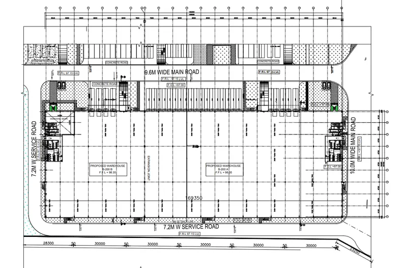
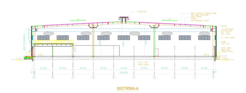
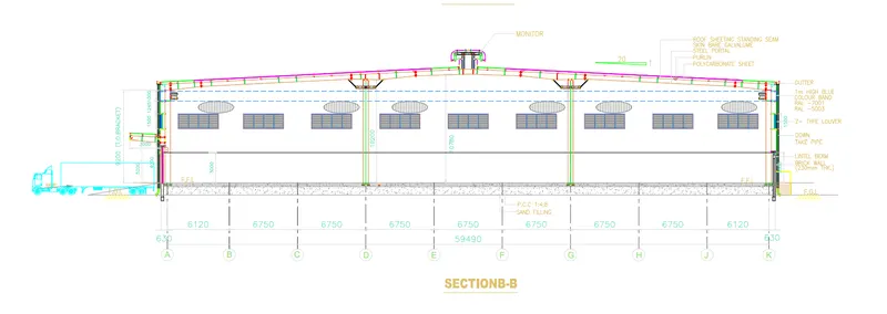
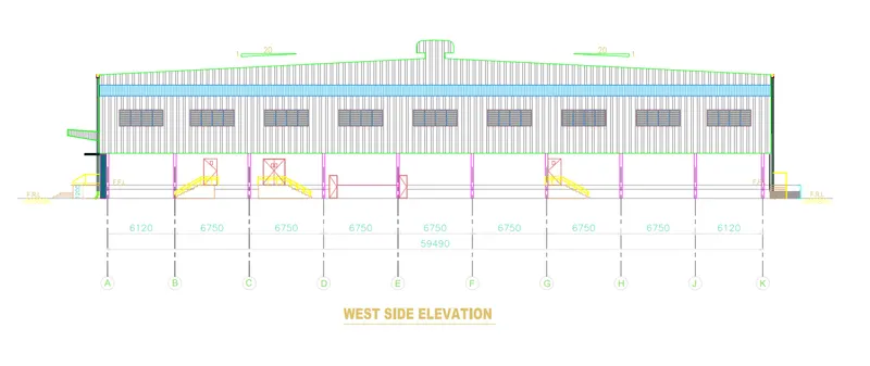
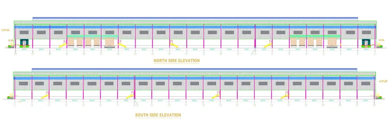
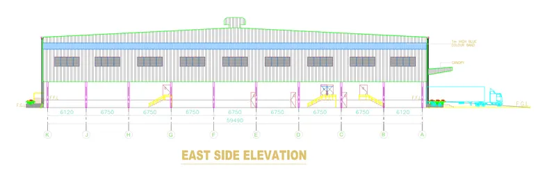
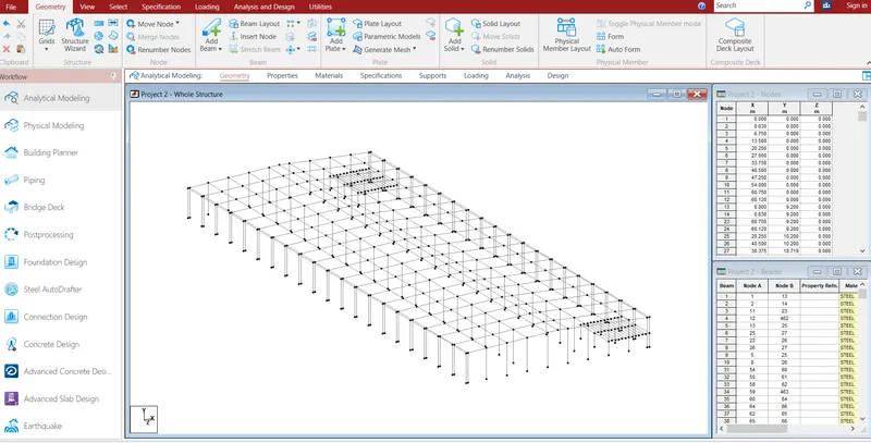
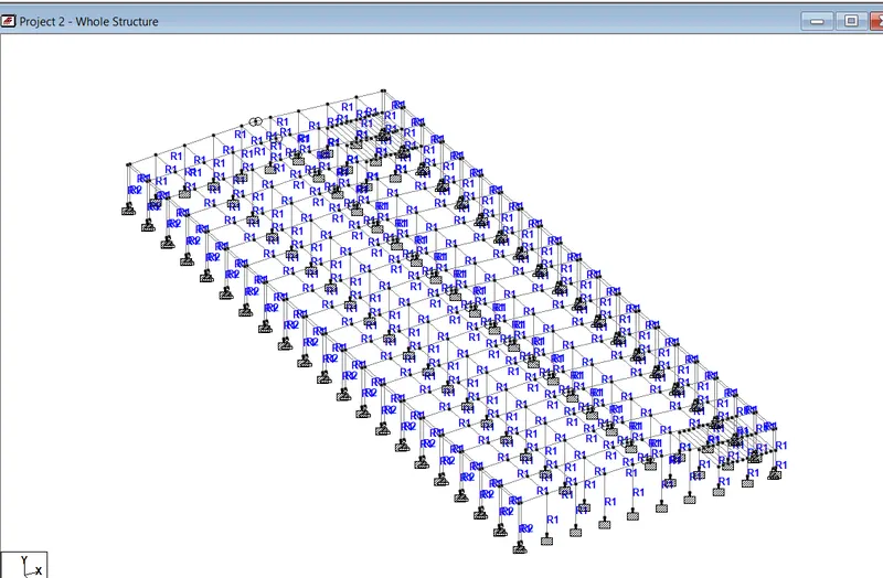
Modelled PEB frame in STAAD pro
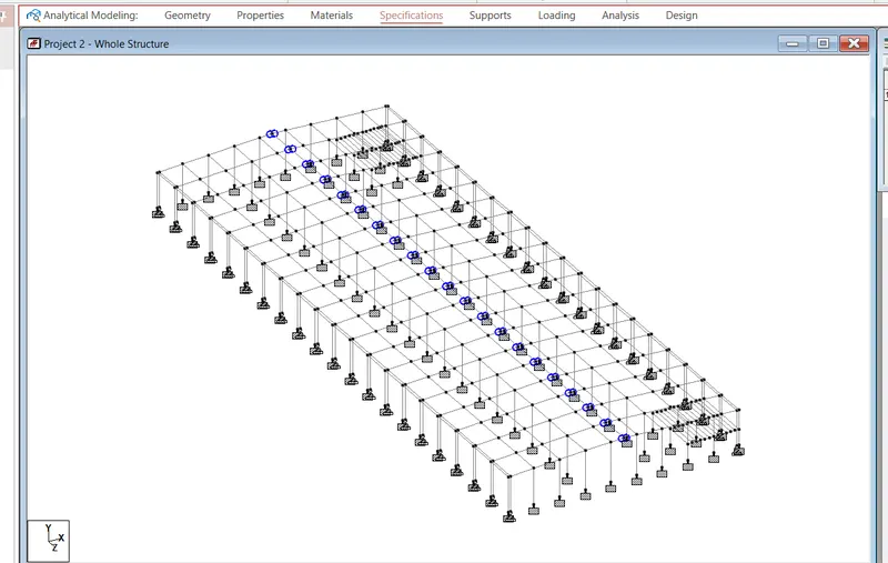
Supports are added to the column as needed and releases and specifications are also applied wherever necessary in the modelled frame
All the section properties and materials are apllied to all the members
Calculation of Design Loads on PEB warehouse:-
Dead load
1.D.L on rafter
- Weight of roof sheet =5Kg/m2
- Weight of purlin and sag rods = 5Kg/m2
- Additional weight = 5Kg/m2
- Total weight of rafter =15kg/m2
- D.L on rafter =15*10*8 =1200N/m =1.2Kn/m
1.D.L on purlin = 10*10*8 =800N/m=.8KN/m
2.Mezz slab self weight (150mm thick slab) =0.15*25 =3.75KN/m2
3.Floor finishes and additional load on mezzaline floor = (150+500)Kg/m2 =KN/m2
4.Weight of 230mm thick brick wall (4m height ) on mezzaline floor =20*.23*4 =18.4KN/m
Live Load
- Live load on roof and canopy = 57Kg/m2*10* 8=4.56kN/m
- L.L on mezzaline floor =400Kg/m2 =4KN/m2
Collateral load
Collateral load on roof
- Load on electrical fitting s= 0.1KN/m2
- Load on sprinklers = 0.03kN/m2
- Load on rockwool insulation and dubble wrap insulation =0.15kN/m2
- Load on solar panels = 0.15Kn/m2
- Load on ceiling =0.1Kn/m2
Total Collateral load on roof =0.53*8 =4.24Kn/m
1.Collateral load on mezzaline floor (due to false ceiling and electrical fittings) =0.2*8 =1.6KN/3
2.Collateral load on column due to bracket beam
- Load due to service line supported on the beam spanning 8m width =150kg/m*8*10 =12Kn
- Moment acting on column due to service line =12*0.75 =9knm
3.Collateral load on jack beam due to service line = 2.5Kn/m
4.Collateral load on mezzaline false ceiling = 3.2Kn/m
Wind Load
Basic wind speed =39m/s
K1 =1.00
K2 =1.05 (Terrani Catogory-1. Building height at eaves = 10.50 m)
k3 =1.00
K4 =1.00 (For other structures)
Kd =0.9
Ka(rafter )-0.8 or as per tributary area.
Ka(Column) - 0.8245 or as per tributary area.
Ka(Purlin) - 0.9721 or as per tributary area.
Ka(Side Runner) - 0.978 or as per tributary area
Kc -0.9
Design wind pressure =pd= kd*ka*kc*0.6*(Vb*K1*K2*K3*K4)^2 = 0652kn/m2
Should not be less than 0.7Pz =0.7*1.006 =0.704 kN/m^2
Cpe -As per table 5 & 6 of IS 875(part 3)-2015
h/w =10/60 =0.6
L/w =170/60 =2.83
Cpe on wall :
| Direction | A | B | C | D |
| 0 deg | 0.7 | -0.25 | -0.6 | -0.6 |
| 90deg | -0.5 | -0.5 | 0.7 | -0.1 |
Cpe on roof :
Roof angle =2.86
| Durection | EF | GH | EG | FH |
| 0 deg | -0.86 | -0.4 | ||
| 90 deg | -0.8 | -0.4 |
Cpi =0.2
Wind load on columns =(Cpe -Cpi)*A*Pd
Wind about X direction +Cpi on wall A = (0.7-0.2)*8*0.704 = 2.816kn/m
Wind about X direction +Cpi on wall B = (-0.25-0.2)*8*0.704 =-2.534kN/m
Wind about X direction +Cpi on wall C & D =(-0.6-0.2)*6.75*0.704 =-3.802KN/m
Wind about X direction - Cpi on wall A = (0.7+0.2)*8*0.704 = 5.069kn/m
Wind about X direction - Cpi on wall B = (-0.25+0.2)*8*0.704 =-0.282kN/m
Wind about X direction - Cpi on wall C & D =(-0.6+0.2)*6.75*0.704 =-1.9 KN/m
Wind about Z direction +Cpi on wall A = (-0.5-0.2)*8*0.704 =-3.942kn/m
Wind about Z direction +Cpi on wall B = (-0.5-0.2)*8*0.704 =3.942kN/m
Wind about Z direction +Cpi on wall C =(0.7-0.2)*6.75*0.704 =2.376KN/m
Wind about Z direction +Cpi on wall D =(-0.1-0.2)*6.75*0.704 =-1.425KN/m
Wind about Z direction - Cpi on wall A = (-0.5+0.2)*8*0.704 =-1.689kn/m
Wind about Z direction -Cpi on wall B = (-0.5+0.2)*8*0.704 =-1.689kN/m
Wind about Z direction - Cpi on wall C =(0.7+0.2)*6.75*0.704 =4.276KN/m
Wind about Z direction -Cpi on wall D =(-0.1+0.2)*6.75*0.704 =0.475 KN/m
Wind load on rafters =(Cpe -Cpi)*A*Pd
Wind about X direction +Cpi = (-0.86-0.2)*8*0.704 = -5.970Kn/m on side A rafter
Wind about X direction +Cpi = (-0.4-0.2)*8*0.704 =-3.378 kN/m on side B rafter
Wind about X direction - Cpi = (-0.86+0.2)*8*0.704 = -3.716Kn/m on side A rafter
Wind about X direction - Cpi = (-0.4+0.2)*8*0.704 =-1.125 kN/m on side B rafter
Wind about Z direction +Cpi = (-0.8-0.2)*6.75*0.704 = -4.752Kn/m on side C rafter
Wind about Z direction +Cpi = (-0.4-0.2)*6.75*0.704 =-2.851 kN/m on side D rafter
Wind about Z direction - Cpi = (-0.8+0.2)*6.75*0.704 = -2.851Kn/m on side C rafter
Wind about Z direction - Cpi = (-0.4+0.2)*6.75*0.704 =-0.850kN/m on side D rafter
Wind Load on Canopy :
Cp -As per table 8 of IS :875 (part 3)-2015
Roof angle 2.86deg
Cp -ve =1.08
Cp +ve =0.35
W.L on canopy (upward) =1.08*8*0.704 =6.082kN/m
W.L on canopy (Downward) =0.35*8*0.704 =1.971 kN/m
Seismic load :
As per IS 1893:2016
Seismic zone -III -Z =0.16
Rf -4.0
I-1.0
SS -3.0
- 25% L.L on roof is considered for calculation of seismic forces
- 100% of collateral load is considered for calculation of seismic forces
- 50% (live load +Collateral load) on mezzanine floor is considered for calculation of seismic forces
- 100% of Dead load is considered for calculation of seismic forces,
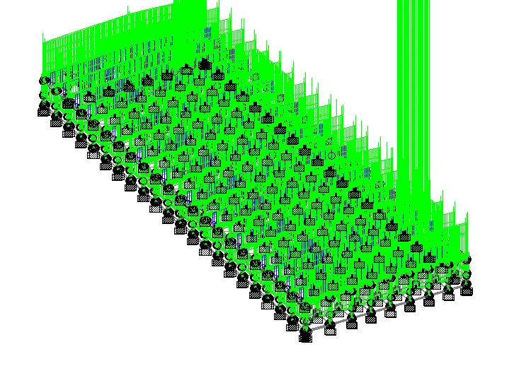
Loading has been applied on the model
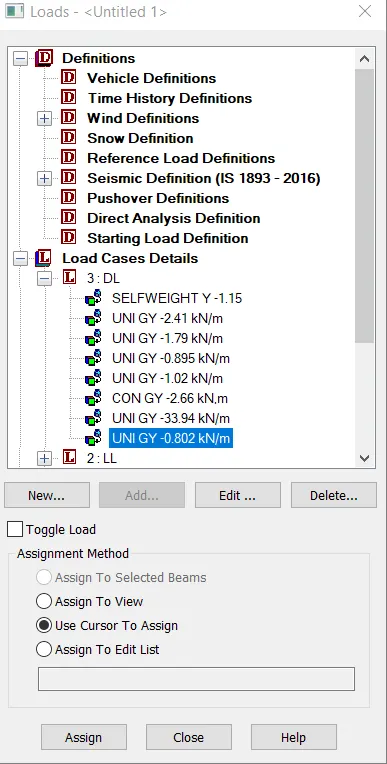
Load on modelled structure
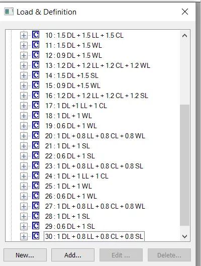
All the load combinations are applied
Design parameters
IS 800LSD
FYLD =345000 for portal frame and mezz bea,s
FYLD = 250000 for bracings
Beam =-1
STP =2 for welded sections
Main = 250 for tie beam
Ly =Lx =1.5m for rafter
Ly =Lx =3.25m for columns
Ly =Lx =4.43 for colums supporting canopy
Lz =11m for internal columns
Ly = Lx =0.5m for mezzanine floor beams
Lz =6.75m for mezzanine floor beams
Ly =1.7m
Ratio =1
Run the analysis on the PEB structure and check for errors.
Result : PEB Warehouse has been successfully modelled and designed .