Project 2
Develop general arrangements for the RC office building. Analyze and design the building as per IS standard code in TEKLA STRUCTURAL DESIGNER. Refer the attached plan and elevation. The building to be designed for dead, live, wind and seismic loading.
Report of each member to be generated and extract drawings for structural plans, beam reinforcement details from the software
AIM:
To Develop general arrangement for the RC office building. Analyze and design the building as per IS standard code in TEKLA STRUCTURAL DESIGNER. Refer the attached plan and elevation. The building to be designed for dead, live, wind and seismic loading.
and to Report of each member to be generated and extract drawings for structural plans, beam reinforcement details from the software
TOOLS REQUIRED:
new
file
grid
construction level
grid
beam
column
manage property set
slab
project window
property browser
seen content
save as
load
load cases
load combinations
dead load
live load
seismic wizard
IS code
excel sheet
wind load
analysis
1st order linear analysis
check member
interactive design
model report
show report
settings
roof panel
wind panel
foundation
catalog
pile base column
drawing setting
layer style
layer configuration
sub surface
frames
area load
full UDL
construction lines
PROCEDURE:
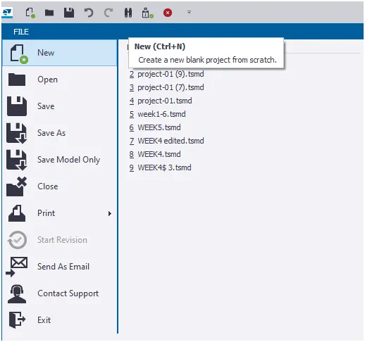
1.Firstly let us open a new file in Tekla software using new icon present in file tab.
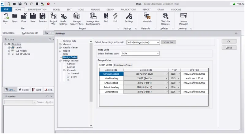
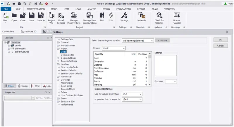
2. Now let us select the settings icon from the home tab and After selecting the settings icon a dialog box appears then let us modify settings according to our model that includes design codes, units.
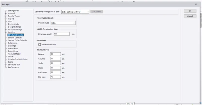
3. Now we will set up the model for the given parameters by using structure defaults.
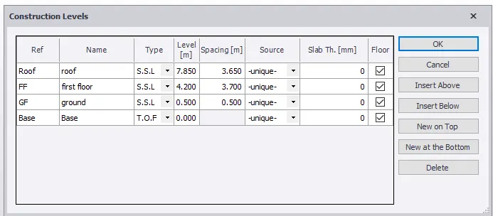
4. Now let us primarily model the construction level and name them according to our plan.
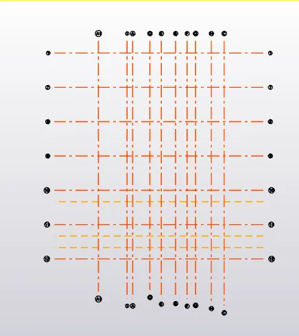
5.now select any construction level which can be accessed through project browser and now according to the model plan provided in the attachment model the grid lines, we can make use of the parallel quick option to model grids.
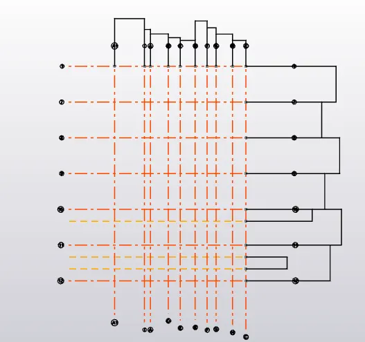
now let us dimension those grids by using dimension icon present in the model toolbar.
column modeling
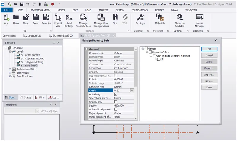
6. Now let us model column for the model for that Now select the manage property set icon present in the home tab
7. After selecting the manage property set icon a dialog box appears, let us select concrete column and select the required parameters( grade, crossectional area)
8.now select column icon present in the model toolbar and according to the plan, model the columns in our model.
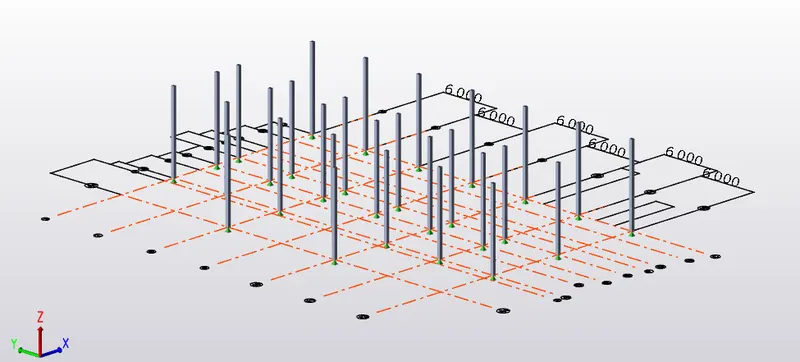
9.using the properties window we can alter the properties of the column
modelling beams for our model
10. for that let us model beams for that similar to columns let us create new property beam with the help of manage property set icon
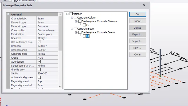
, Using project window let us select a construction level say ground floor. followed by the first floor and roof.
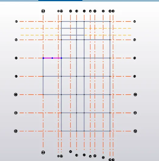
now our model after beams modeled
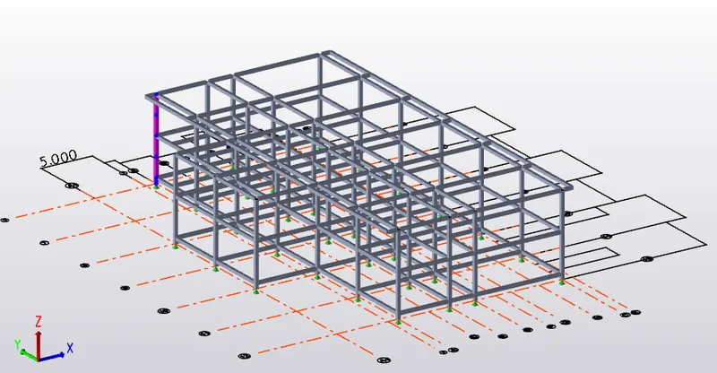
slabs icon
12. for that select slab icon present in the model toolbar before that let us create a new property set using
manage property set.
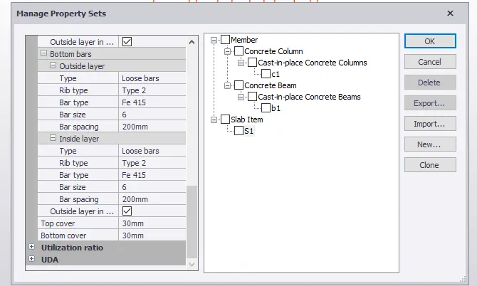
13. providing slab to model for ground floor which can be accessed through project browser followed by modeling in first floor.
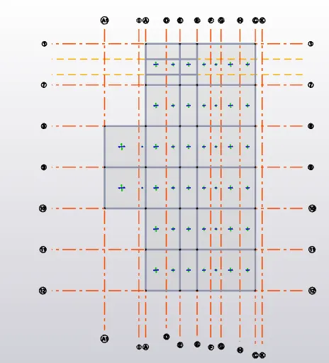
view in 3D
14. Now let us model staircase for that
select the corners where we are designing staircase and right-click on them
lots of options that appear select add to substructure option and name it
now access it through project browser and select slop sloped frames option and select the corners
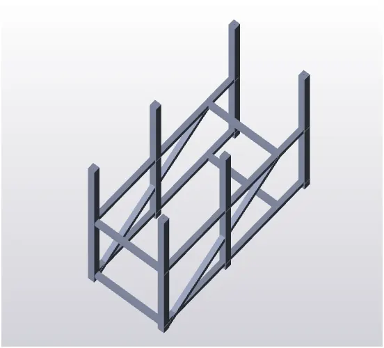
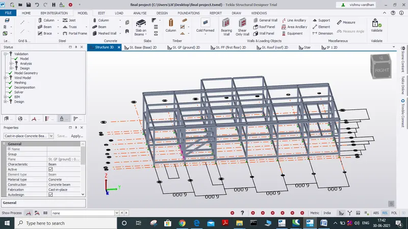
we can see that we have modeled stairs to our model.
now let us apply loads to our model
15. DEAD LOAD
- finishers of 50 mm
50 mm X 24 ( acc to IS CODE) = 1.2 KN/M
- Slab thickness as per design
it is automatically calculated in Tekla software
- brick wall load
it is generally given by the formula
=HEIGHT X UNIT WEIGHT X BRICKWALL THICKNESS
- from ground floor to the first floor
height = 3.7 m
unit weight = 20 kn/m
brick wall thickness let us assume 150 mm
dead load from ground floor to the first floor
= 3.7 m X 20kn/m^3 x 0.15m = 11.1KN/M
- from FIRST FLOOR floor to roof bottom
- height = 3.65 m
unit weight = 20 kn/m
brick wall thickness let us assume 150 mm
dead load from the first floor to roof bottom
= 3.65m X 20kn/m^3 x 0.15m =10.95 KN/M
- ROOF WALL LOADING
- check for the slope of the roof in or model it is 0 degrees
- for every raise in 10 degrees, we must reduce load acting by 0.02.
- as per IS code, we are going to apply an area load of 1.5 KN/M^2
= 1.5-0(0.02)=1.5KN/M
roofing load to be applied on the model is 1.5 KN/M
- APPLYING DEAD LOAD ON THE MODEL
16. Click on the load option and select the load cases icon.
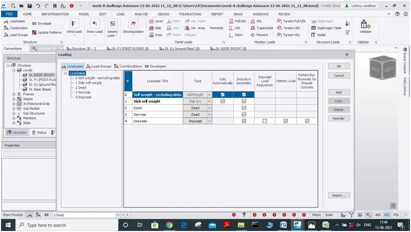
17.A dialog box appears, check for the dead load is if not there, add it and Then go to load icon and from the drop-down box select dead load.
for finishers
select area load and apply on the construction level and using the property window assign the value which we got by calculation. (1.2 KN/M)
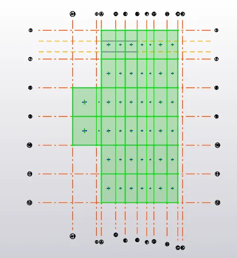
18. for brick wall loading select load type as full udl load and according to our calculated values apply it for both the first floor as well for ground floor
FOR GROUND FLOOR TO FIRST FLOOR
BRICK WALL LOAD TO BE APPLIED IS 11.1 KN/M
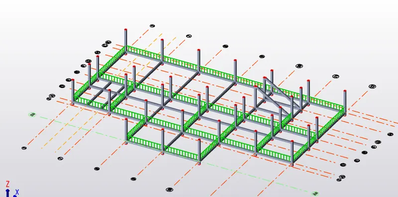
FOR THE FIRST FLOOR TO ROOF BOTTOM
BRICK WALL LOAD TO BE APPLIED IS 10.95 KN/M
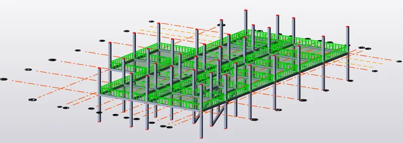
19. now let us apply roof load
select area load option and go to roof with the help of project window and by assigning the load as 1.4KN/M
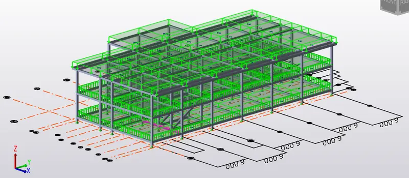
final 3D view after dead loads are applied on our model
now let us apply live load on our model
20. select the load cases icon option and add a new load case under imposed load category and name it as
imposed/live load.
21. now arrange is code (IA 875 PART-2) AND NOTE THE REQUIRED LOAD VALUES FOR OUR MODEL

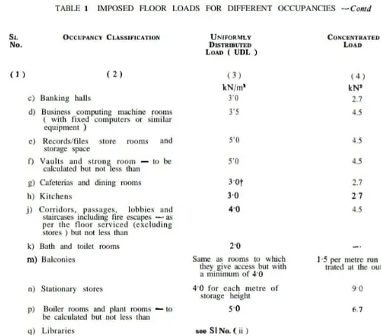
22.FROM the drop-down box select load as live load, now select area load and according to the defined value as per IS CODE and assign load value acc to the purpose it serves
to say let us apply live load for the corridor
say let us select area load
now assign the load as 4.5 KN/M
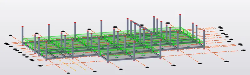
ground floor view after applying live load
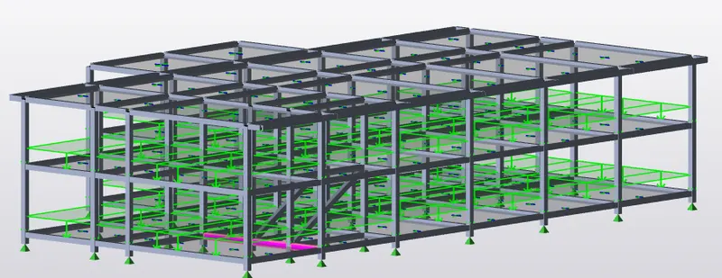
view of our model in 3D after applying live load to our model
23. Before applying wind load let us model roof panel and wind panel to our model
for applying wind panel select the wall panel icon and select the corners of the wall for which we are going to
model roof panels
* continue to do it for the remaining walls.
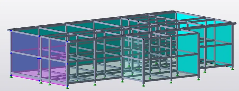
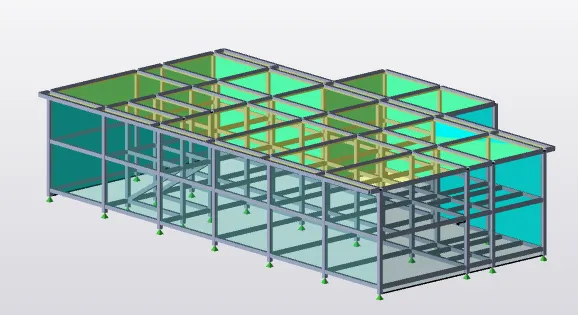
24. in a similar way of what we have modeled wall panel we can model roof panel with the help of roof panel icon by selecting the corners of the roof.
3D view of the structure after modeling roof panel
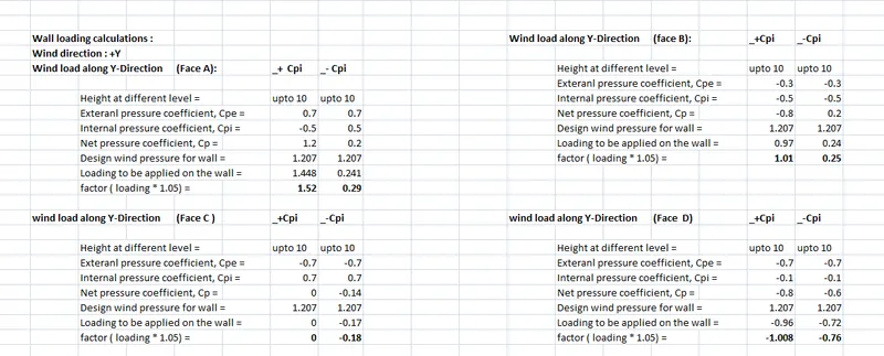
25. now let us perform wind load calculations to be applied to our model
1.For performing wind load calculation let us make use of excel sheet so let us open excel sheet
2.Now let us assume and assign the given details i.e
- Basic wind speed = 50m/s
- Terrain category 2
- now let us find out the dimensions of the model using the dimension icon and note it down in the sheets.
- Now let us find the coefficient K1, K2, K3, K4
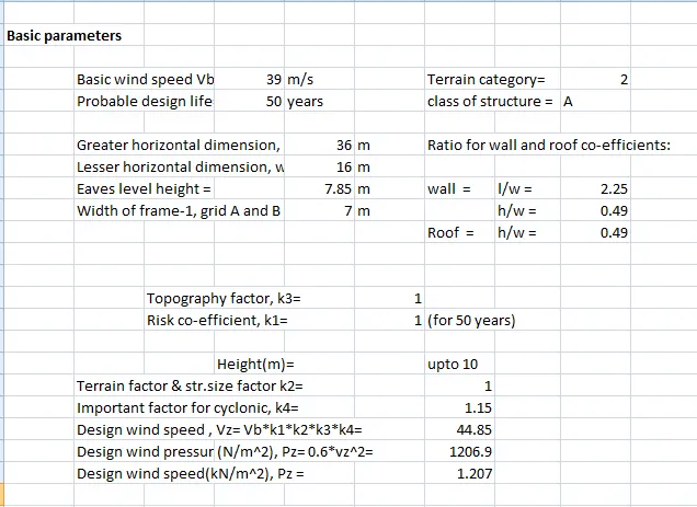
- Now after calculating K1, K2, K3, K4 we can calculate design wind speed followed by design wind pressure
by the formulae
Vz=Vb X K1 X K2 X K3 X K4
Pz=0.6 VZ^2
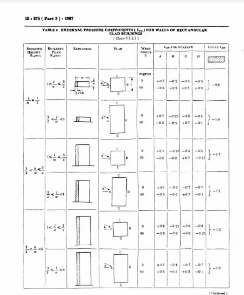
by calculating l/w,h/w ratios and looking for Is 875 part 3 for the values to be implemented in our model
and calculate the load to be applied to our model in all the directions
26. and now let us apply load to our model
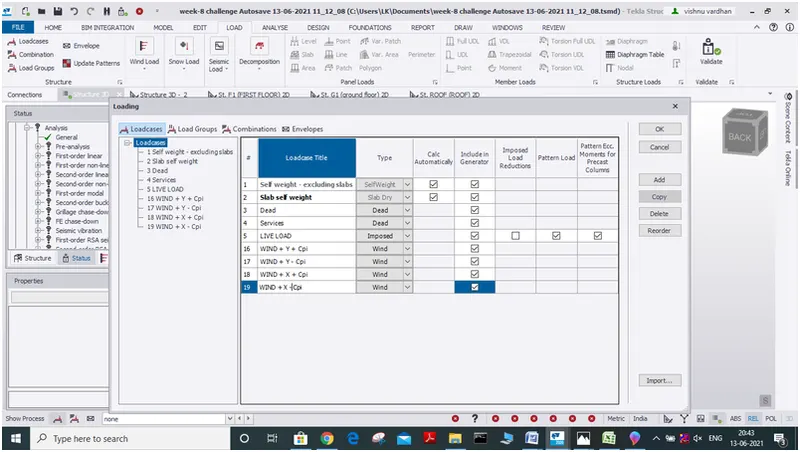
1. for that Now let us select load cases icon and add 4 loads and assign them to wind load and name them as
WIND + Y + Cpi
WIND + Y - Cpi
WIND + X + Cpi
WIND + X - Cpi
2. Now from the drop-down box select the load as any one of the created wind loads
say WIND + Y + Cpi
3. Now select the area load option and for the following load group change the alignment to global y-direction and assign the value of load from the calculation for the face that is selected.
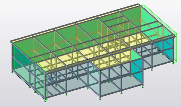
4. In the same way apply the load WIND+ Y + Cpi for the other face that is along the y-axis
5. similarly apply other wind loads in other faces of the model.
6.similarly apply loads on the faces that are along the faces of the x-axis.
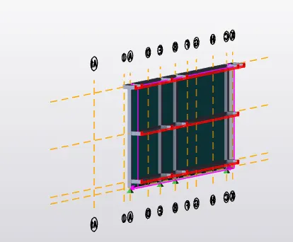
7. We can also make use of the frame icon to apply wind load and check how the wind load is acting is it acting away or towards the structure.
27. now let us apply seismic load to our model
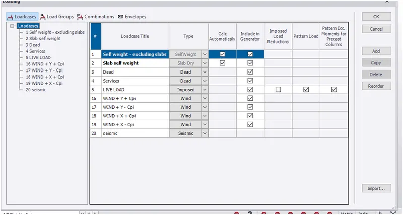
1. Now select the load cases icon present in the load toolbar then a dialog box appears add a new load by clicking on the new option and assign the type of load as seismic and name it as seismic load.
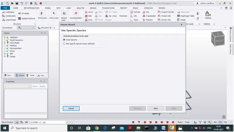
2. now select the seismic wizard icon present in load toolbar.
a new dialog box appears asking for analysis procedure to be used
let us select code spectra and click next.
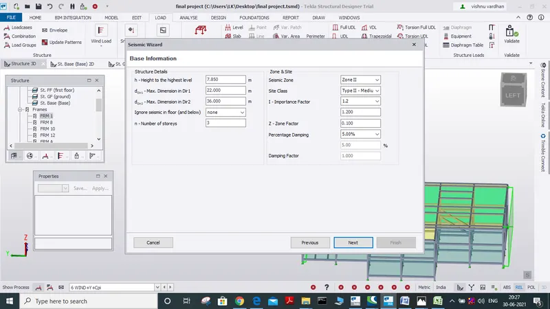
3.now a new dialog box appear where we can see some information is directly assigned from the model and also select the seismic zone as 2
( given) and click next
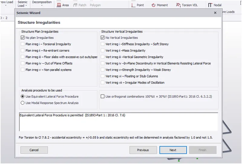
4. a new dialog box appears now select no plan irregularities
analysis procedure select as use equivalent lateral force procedure
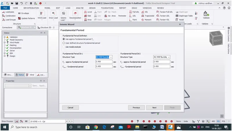
5. fundamental period dialog box appears then select the option as below and click next.
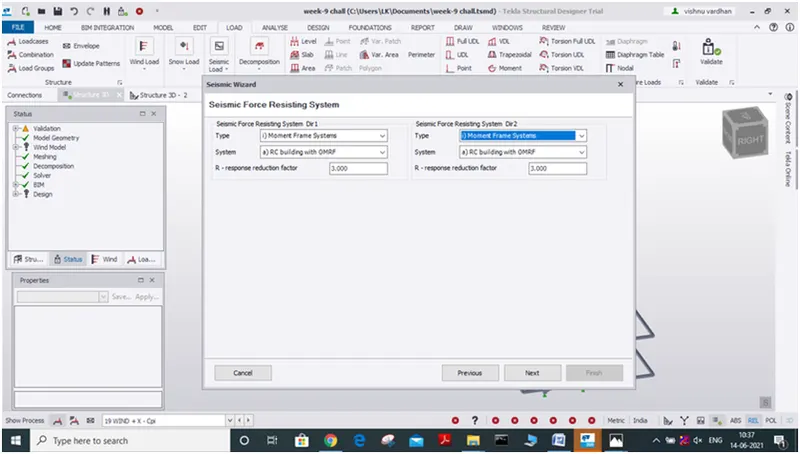
6. seismic wizard force-resisting system dialog box appears, assign them as follows
then click next
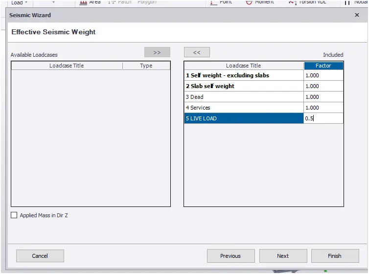
7. now effective seismic weight dialog box appears select the load and assign its factor and click next.
ask to location let us skip and select finish.
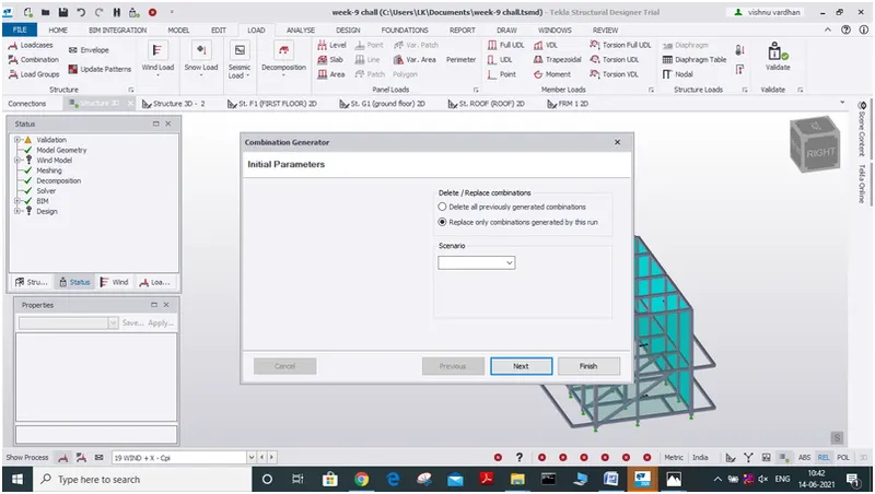
8. now combination generation dialog box appears,
select the option replace only combinations during the run and click next
9.now a new dialog box appears
asking load combinations for combination followed by service
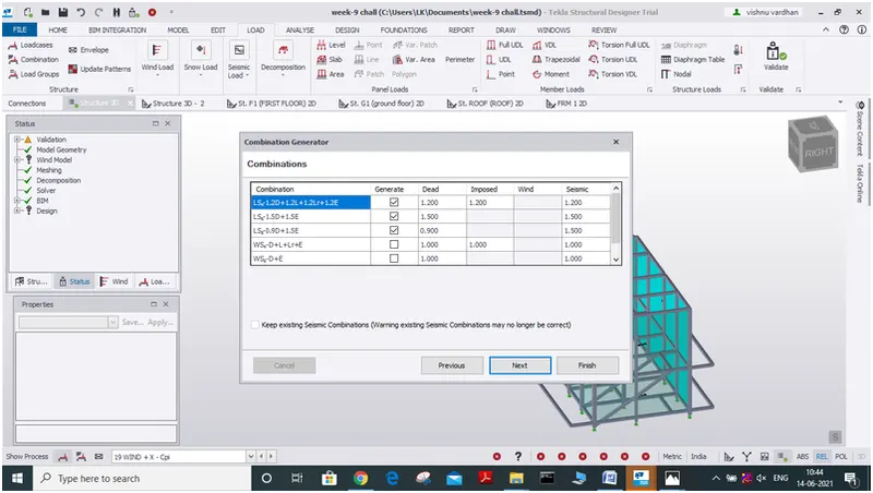
select the required load combination and click finish
10. we can see new load cases are generated for seismic loading.
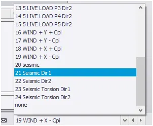
11. from the drop-down menu we can select the load cases to see how a seismic load is acting
28. now let us check 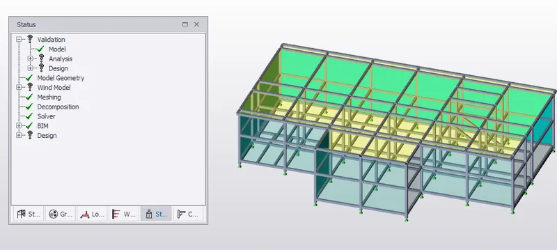 the model before analysing the model for that let us make use of validate icon.
29. now let us analyse the model
1. now before performing analysis we can check for some settings for that open settings icon present in the home tab
2. A dialog box appears now select 1st order linear analysis and check for iteration and tolerance.
similarly, check for modification factor and adjust it to 1.
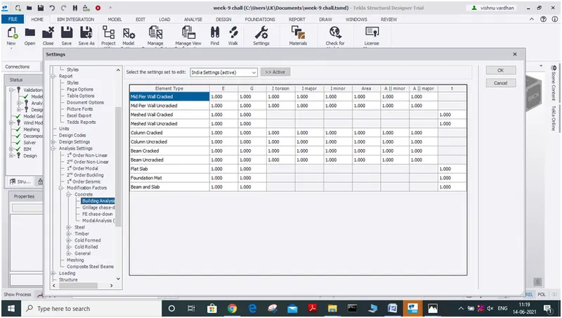
3. Now let us perform analysis of the model for that select the analysis icon and select 1st order linear analysis.
4. after selecting 1st order analysis a new dialog box appears it asks for load cases and load combinations
to be considered for analysis let us select all the load cases and load combination then click ok.
5. then the analysis is done and we can see the analysis reports in the property window
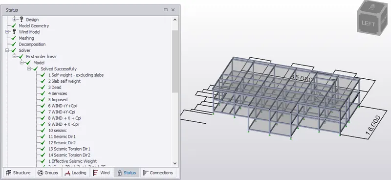
- as we can see our model has been analyzed and no need of any alterations to the model as the model passed the tests.
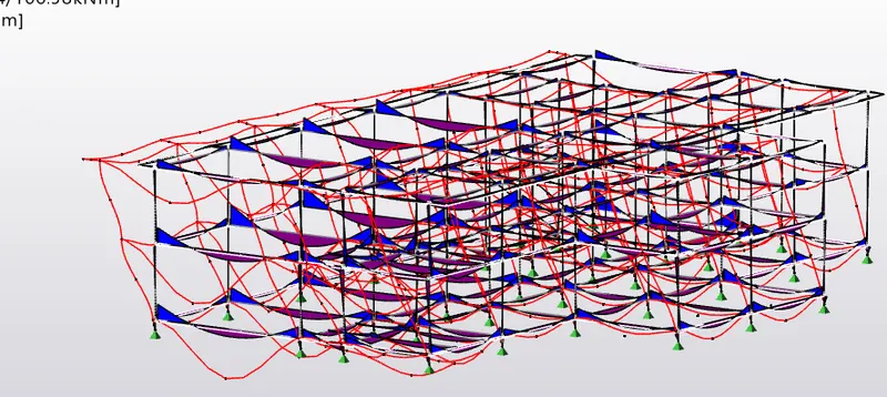
- now let us see the deflection, shear force, bending moment of the model
- so for that let us go to review view of the model.
- now let us look at how the deflection of the model for different load combinations by simply changing load combinations from the drop-down box.
load combinations as well
now similarly we can also check for the bending moment of the model due to load combinations
simply by selecting moment major/moment minor,shear major/minor
shear major for different load combination can be seen by changing load combinations
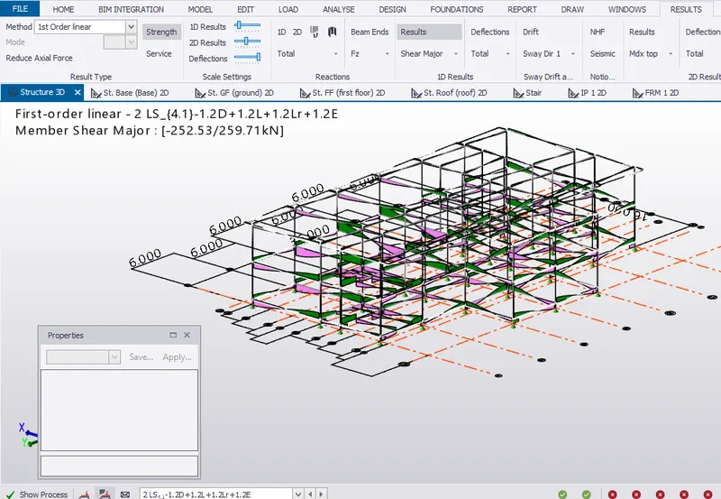
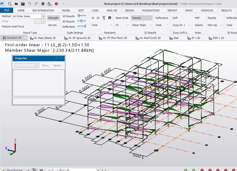
similarly for moment major
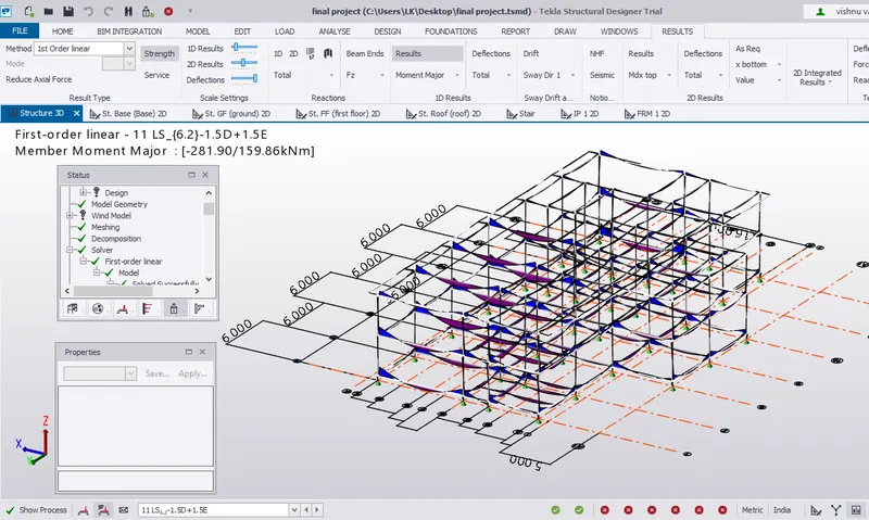
in similar way we can observe deflections for different load cases/combinations.
30. design of column for our model
1. now select any of the column member from the model and right-click on the member
let us select say C14
2.now a lot of options will appear after right-clicking on the member.
3. From that we will select the interactive design option followed by selecting static.
4. a new dialog box appears, check whether it passes the tests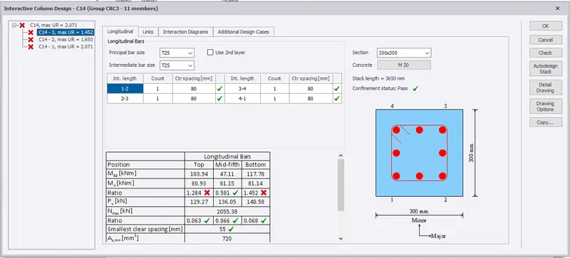
here our member fails in one test so we have changed its properties to make the member pass the test
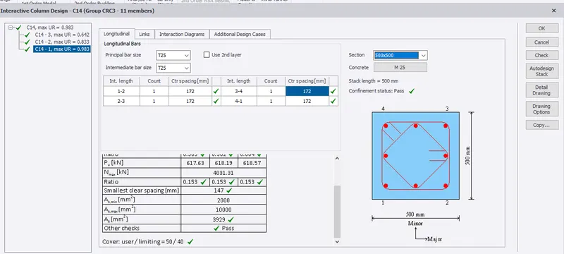
- once this clears all the tests we can use the same properties to similar members click ok
- there is a new dialog box that appears stating that apply the same change to all the members let is click ok
we can check whether the changed properties are applied on the other members so let us select any other column C11
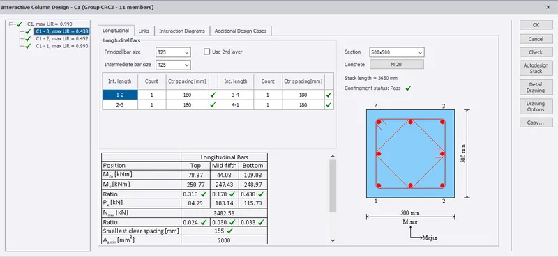
WE CAN CLEARLY SEE THAT THE DESIGN CHANGES ARE APPLIED TO THE REMAINING COLUMN MEMBERS.
31) now we can design beam members.
1. select a beam member and right-click on the beam followed by selecting interactive design option followed by static option from the dialog box.
2. a new dialog box appears showing whether the member passes the tests
for the member we have selected has failed in a test
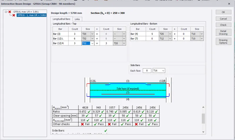
3.now let us modify its properties such that it much clear the tests
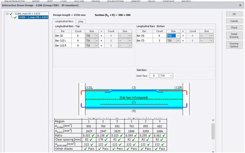
4.there is a new dialog box that appears stating that apply the same change to all the members let is click ok
we can check for other members whether the property is applied
SIMILARLY, WE HAVE MODIFIED THE PROPERTIES OF THE COLUMN AS WELL SUCH THAT IT HAS CLEAR THE
TEST CONDITIONS
32)DESIGN OF SLAB
1.Click on any of the slab item and right-click on it, once you right-click on the slab item a large no of options that appear
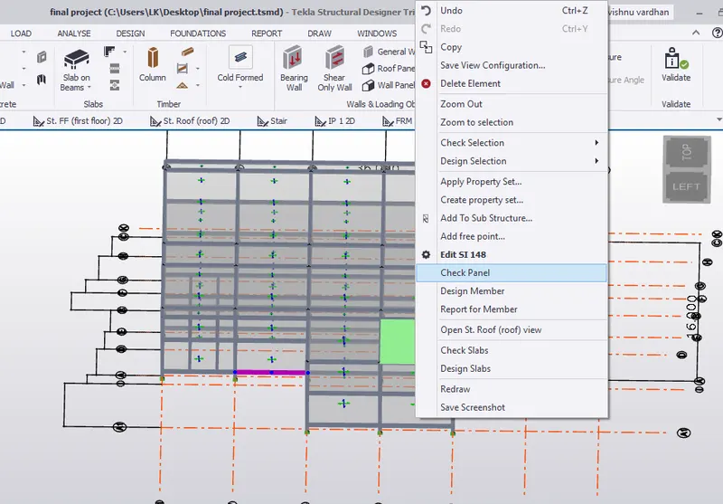
- select the check panel icon a new dialog box appears
- When you click on the check panel option here it displays no-load combinations exist. if it displays no-load combination after selecting check panel option we have to load new load combination once again.
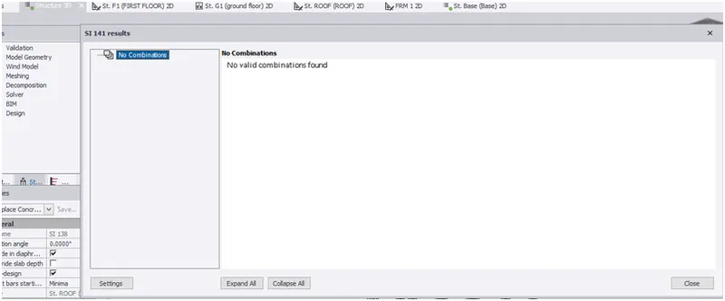
4.now for loading load combinations we have to select the load combinations icon present in load toolbar.
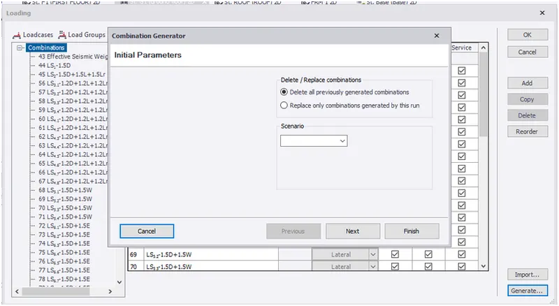
5.after selecting load combination a dialog box appears, select the generate icon then a new dialog box appears select the option delete all previous load combinations.
6. then select the load combinations that are to be considered for the analysis and design.
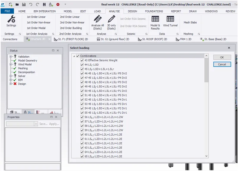
7.now let us perform analysis for that let us select 1st order linear analysis, after selecting a dialog box appears which displays load combinations,load cases select the required load combinations and cases and click ok.now check for errors and correct them by varying properties of members.
8.now select analyse all static icon present in analyse tab now we can design the slab member
- now let us right-click on slab member and select check panel
- Now we can see the status of our member whether our slab member clears the tests/requirements
- here we can see that our member fails in some tests for that we have to change the properties (reinforcement properties, slab properties, grade of concrete)of the model using property window
- from the check panel option we can see that in which tests it fails and calculations are shown, we can make use of these calculations to change the values of reinforcement.
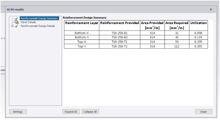
14. now we can apply similar properties of slab for similar slabs for this we can make use of copy property icon present in review view.
BY THE HELP OF SEEN CONTENT WE CAN VIEW THE REQUIRED ELEMENTS.
- In a similar way we have to design for other slabs by selecting the check panel option and changing the properties of concrete.
33) DESIGN OF FOUNDATION
1. go to the foundation toolbar and click on catalog icon
2. a dialog box appears and assign the values as below and click ok
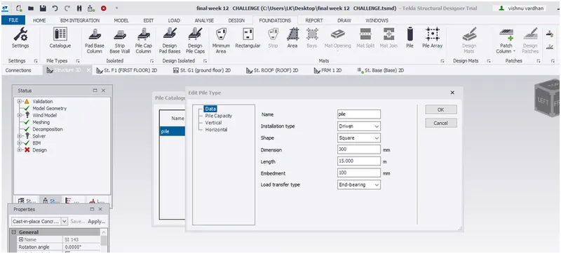
3. now let us go to base level using the project browser and select the pile cap column icon.
4. now let us model the foundation just by select a point near the column and dragging it and foundation is modeled.
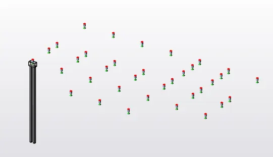
5.Now right click on the foundation member and select the option check member
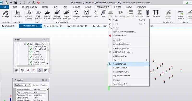
6. after selecting check member icon a new window appears which shows whether our member clears all the tests/requirements
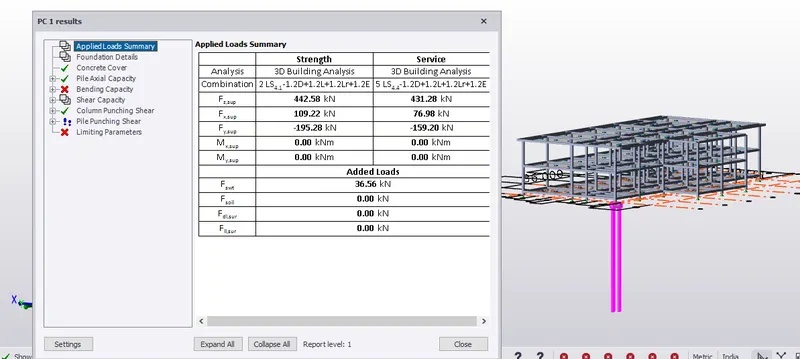
7.if the members fail in any tests we have to modify its properties using property window such that the foundation member clears all the tests.
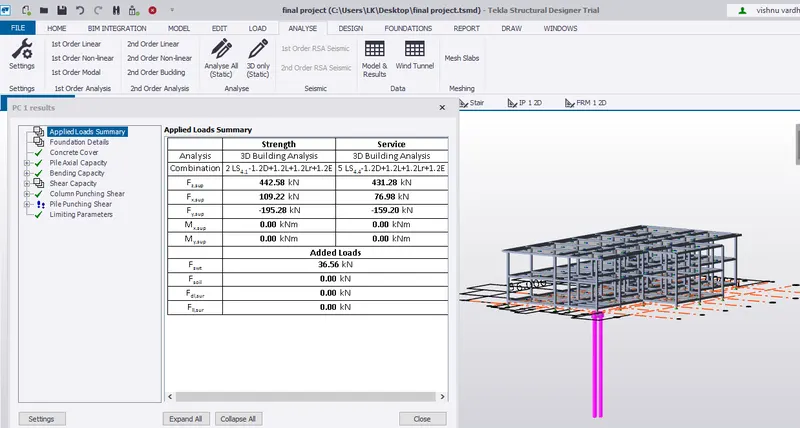
8.now in the similar way, we can model the foundation to remaining column members and check the foundation member using check panel icon.
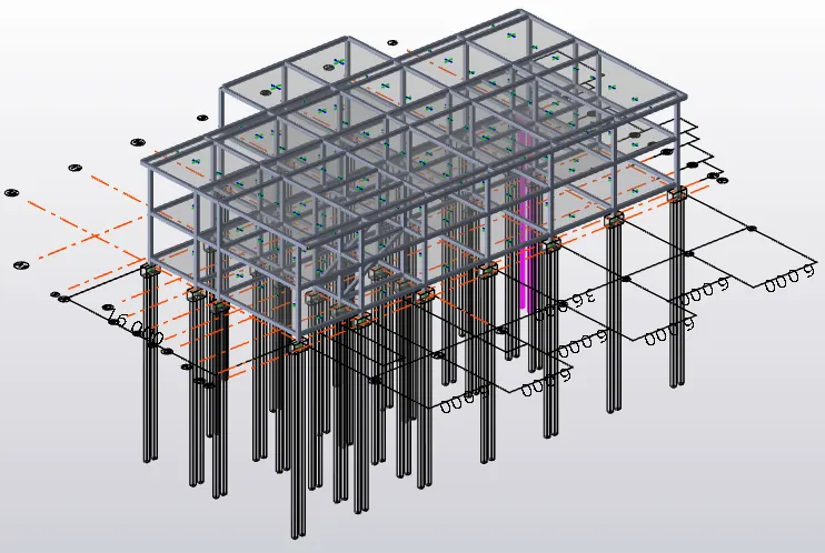
AND IN 3D
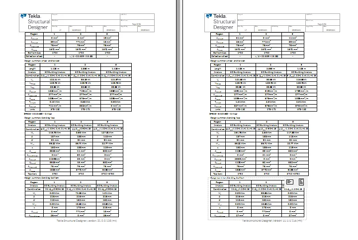
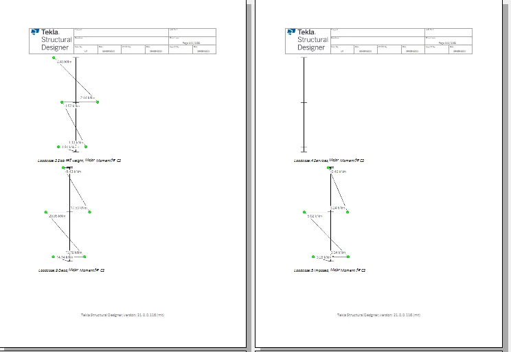
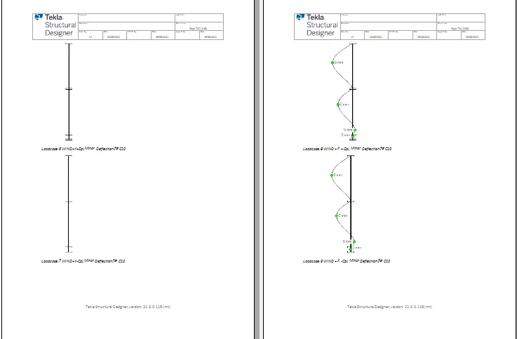
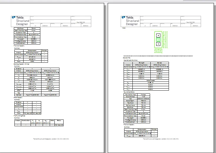
34. now let us generate report to our model
1. for that let us Now click on the model report toolbar present in the report toolbar.

2. A new window appears from the window we can select the features that we wanted to show in our report and click ok.
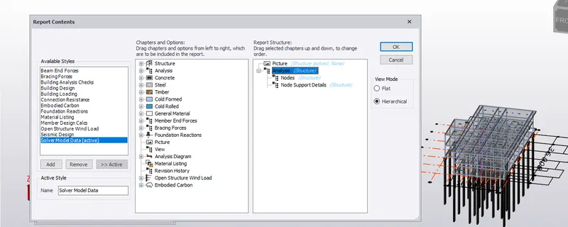
3. now click on the show report icon, the report is displayed with selected parameters and on the right side of report we can see index icon which can help us in navigating to the selected parameter
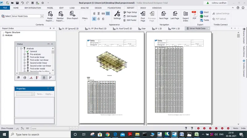
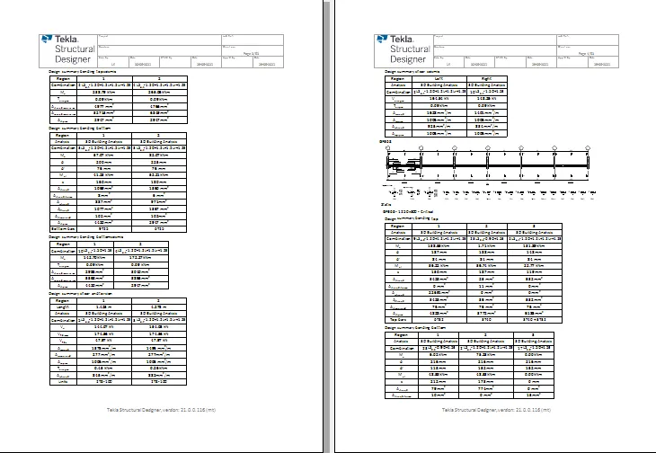
- for our model let us select parameters as load summary, analysis, etc
35)now let us Update the layers settings in the model and generate plan drawings and details from the model.
1. for that primarily select the settings icon present in the draw toolbar.
2.After selecting the settings icon a new dialog box appears and from layer configuration icon we can select the required parameters.
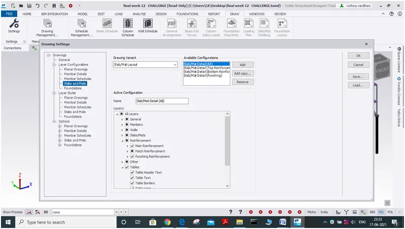
3.now select the layer styles icon here we can change the colors, grid type, font for different elements.
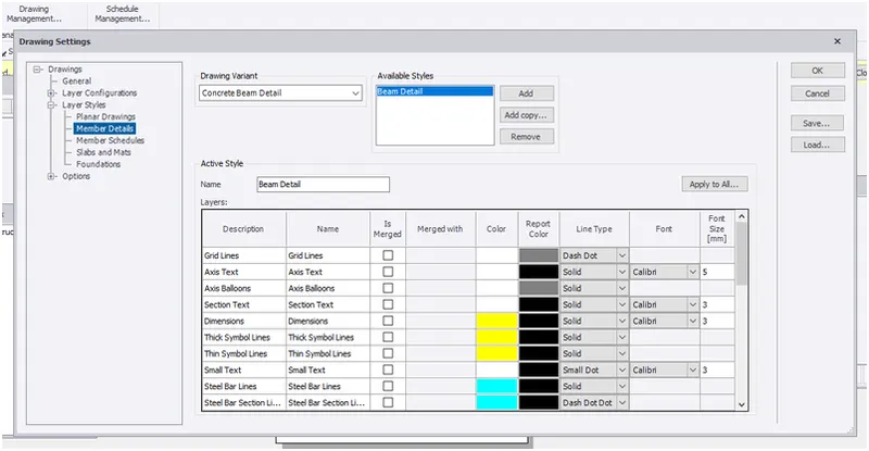
4. we can use different colours for resembling different elements
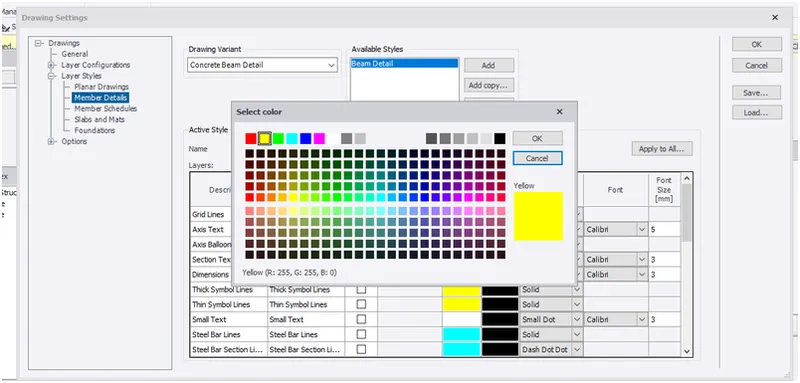
in the same way, we can change font size, line type etc in our drawing and after that we can save it using the save icon and click ok.
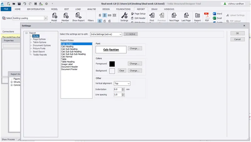
5. now let us select the settings icon from the report toolbar
6.after clicking on the settings icon a new window open where we can edit the style, table format, calculation heading etc
FINALLY SAVE THE PROJECT USING SAVE AS ICON.
RESULT:
we have Developed general arrangement for the RC office building. Analyze and design the building as per IS standard code in TEKLA STRUCTURAL DESIGNERby Refering to the attached plan and elevation. The building to be designed for dead, live, wind and seismic loading.
Report of each member to be generated and extract drawings for structural plans, beam reinforcement details from the software
we have modeled
grids
columns
beams
slab
wall panel
roof panel
foundation
to our model and our final view after modeling of the members is
we have applied loading on our member due to the
dead load
live load
wind load
seismic load.
and loaded our required load combinations.
and then we have analysed our model and also checked the models deflection,shear major/minor,moment major/minor
due to different load combinations
* then we have designed
column,
beam
slab
and checked whether our member passes the tests of load combinations.
* Finally we have generated a report for our model