Project 2
1. Design a Warehouse Building located in Chennai using STAAD Pro Connect Edition. The specification must be as follows:
|
Width |
30m |
|
Length |
50m |
|
Eave Height |
9m |
|
Bay spacing |
6m |
|
Soil type |
Medium |
|
Safe Bearing Capacity |
200 kN/m2 |
|
Roof slope |
1 in 12 |
Assume suitable sections for structural elements. Follow IS800:2007, IS1893 and IS 875
- Prepare a Design Basis Report for the project
- Create structural model using STAAD Pro Connect Edition
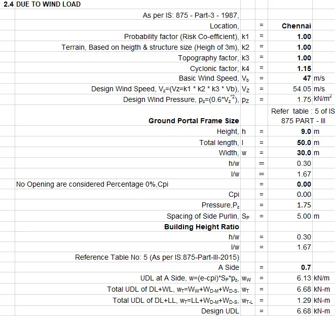
- Prepare DL, LL, WL and EQL load calculations as per IS 875 standards
- Design using MS – Excel
- Steel column
- Rafter
- Base plate
- Pedestal
- Purlin
- Design Foundations using STAAD Foundation.
- Attach necessary sketches and drawings wherever required.
- All stipulations, assumptions and design parameter must adhere to Indian Standards.
Ans=
AIM:- To Design a Warehouse Building located in Chennai using STAAD Pro Connect Edition. Then prepare detailed reports on the following list-
- Prepare a Design Basis Report for the project
- Create structural model using STAAD Pro Connect Edition
- Prepare DL, LL, WL and EQL load calculations as per IS 875 standards
- Design of steel column using MS-excel.
- Design of rafter using MS-excel.
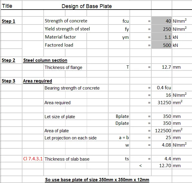
- Design of base plate using MS-excel.
- Design of pedestral using MS-excel.
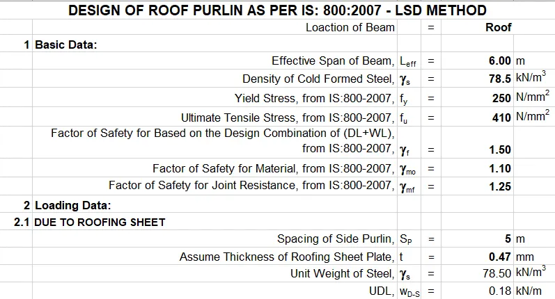
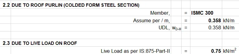
- Design of purlin using MS-excel.
INTRODUCTION:- In this project I will design a Warehouse Building located in Chennai, where plan dimension is 30m in width and 50m in length, eave height is 9m and bay spacing is 6m, roof slope is 1 in 12. Beside this, the soil type is medium soil and safe bearing capacity of soil is 200 KN/m2. Moreover, I have used serveral Indian codal provision like- IS-800 : 2007, IS-808, IS-1893, IS-875 etc while executing the design. Apart from that, I used excel file while design steel column, rafter, base plate, pedestral, Z-purlin.
PROCEDURE:- Here first I will mention question one by one then answer then in the same manner.
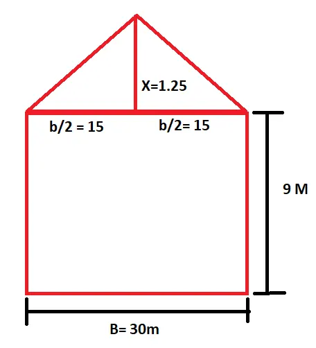
1) Calculation of ridge height:-
Given data-
Width = 30m
Height = 9m
Length = 50m
Bay spacing = 6m
Calculate the central ridge height if roof slope is 1 in 12
Lets assume ridge height is "X".
As per formula
X/(b/2) = 1/12
or, X/(30/2) = 1/12
or, X = 15/12
X = 1.25 m
1) Calculation of Dead load:-
Self weight of structure:-
Factor of safety = 1.15
UDL on Rafter (Main frame):-
Weight of roof sheeting = 5 Kg/m2
Weight of sag rods and braces = 5 Kg/m2
Collateral load = 10 Kg/m2
Total load = 20 Kg/m2 = 0.2 KN/m2
UDL on Rafters:-
Bay spacing = 6m
UDL = 0.2 X 6 = 1.2 KN/m
UDL on Rafters from purlin:-
Choose suitable purlin section for weight of purlin (IS-811)
Say Z = 270 X 75 X 20 X 2.55 = 8.77 Kg/m
weight on rafters from purlin = (Number of purlin X Length of purlin)/Length of rafter
= ( 5 X 6 X 8.77)/15
= 17.54 Kg/m = 0.175 KN/m
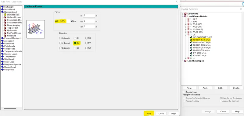
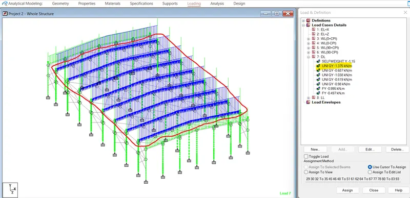
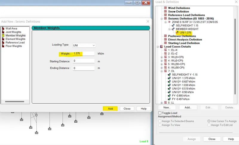
UDL on main frame = 1.2 + 0.175 = 1.375 KN/m
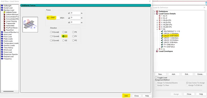
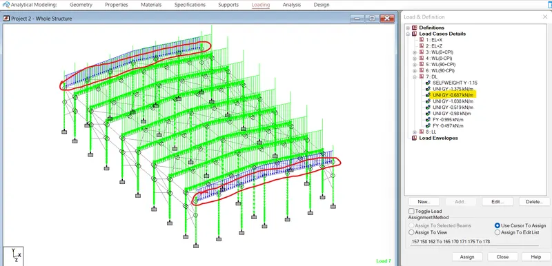
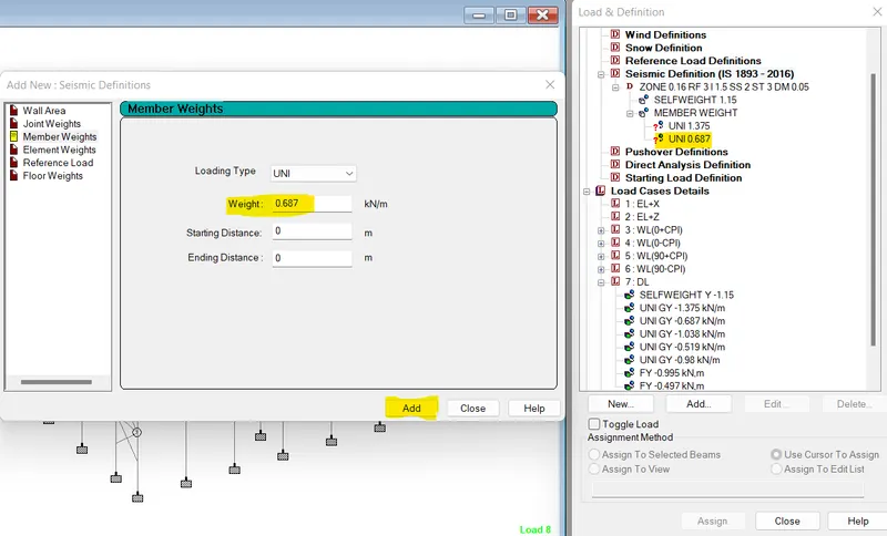
UDL on gable frame = 1.375/2 = 0.687 KN/m
UDL on Column (Main frame):-
Weight of side wall sheeting = 5 Kg/m2
Weight of sag rod and braces = 5 Kg/m2
Load from sag rods & braces = 10 Kg/m2 = 0.1 KN/m2 = 6 X 0.1 = 0.6 KN/m
Weight of grit (270 X 75 X 20 X 2.55) = 8.77 Kg/m
Weight on column = (5 X 6 X 8.77)/6 = 43.85 Kg/m = 0.438 KN/m
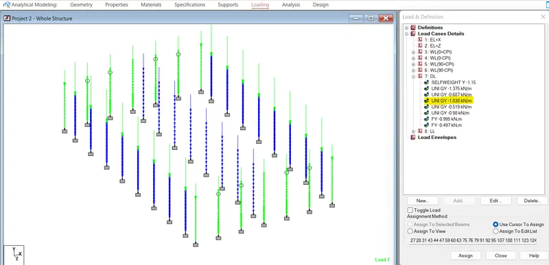
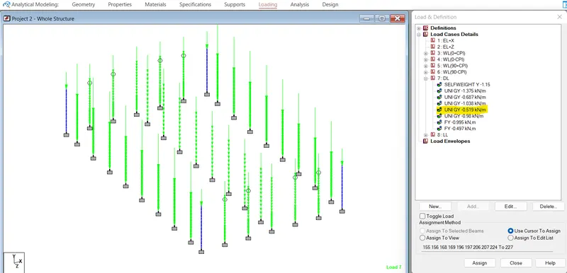
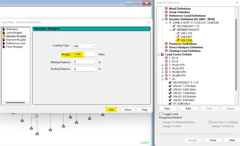
Total Load = 0.6 + 0.438 = 1.038 KN/m
UDL on Column (Gable frame):-
Total load = 1.038/2 = 0.565 KN/m
Load on wind column:-
Load from sheet and sag rods = 0.1 X 6 = 0.6 kN/m
Weight of grits (230 X 75 X 20 X 2) = 6.32 KG/m
Load on wind column = (6X 6.32 X 6)/6 = 37.92 Kg/m = 0.38 KN/m
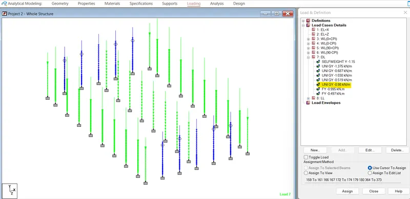
Total load = 0.6 + 0.38 = 0.98 KN/m
Dead Load on eave strut & Gutter:-
Point load:-
Weight of Eave strut = CS 270 X 75 X 20 X 3.15 = 10.7 Kg/m
Weight of eave gutter = 0.25 X 0.25 X 0.001 = [0.25 + 0.25 + 0.25] X 0.001 X 7850 =5.89 Kg/m
Load due to eave strut & gutter = 10.7 + 5.89 = 16.59 Kg/m
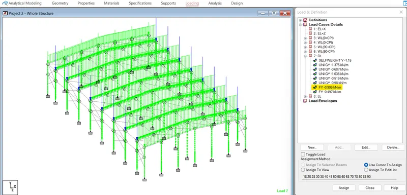
Load due to eave strut & gutter (Main frame) = 16.59 X 6 = 99.54 Kg = 0.995 KN
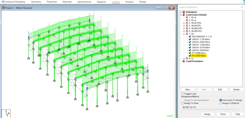
Load due to eave strut & gutter (Gable frame) =0.497 KN
2) Calculation of Live load:-
Live load on roof = 0.75 KN/m2 (IS 875- II)
UDL on Rafter:-
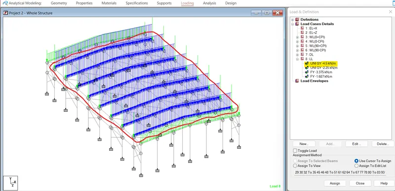
Main frame rafter = 0.75 X 6 = 4.5 KN/m
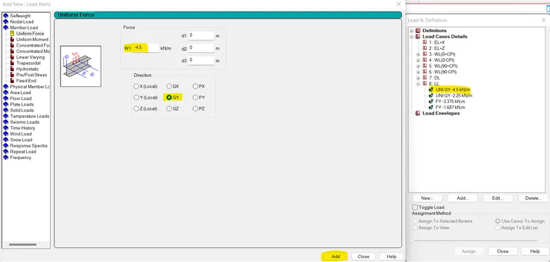
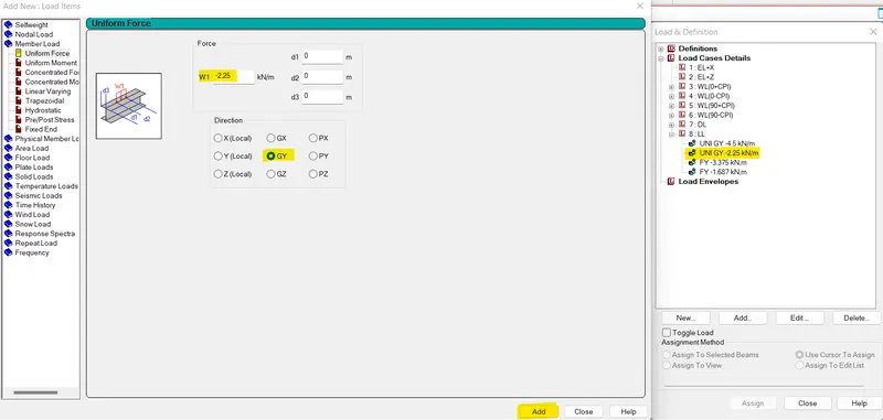
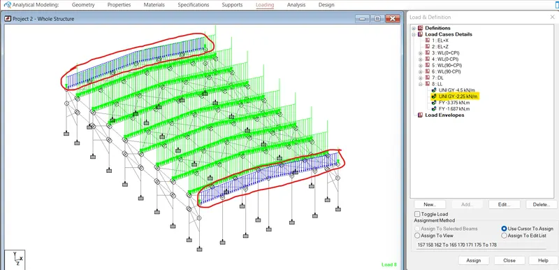
Gable frame rafter = 0.5 X 4.5 = 2.25 KN/m
Eave gutter (250 X 250 X 1mm)
Load due to weight of water in gutter:-
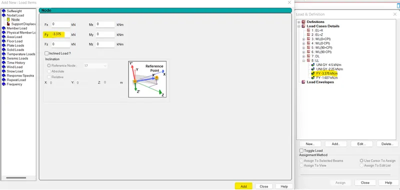
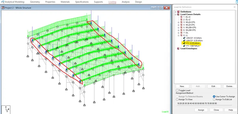
Main frame = [0.25 X 0.25 X 9 X 6] = 3.375 KN
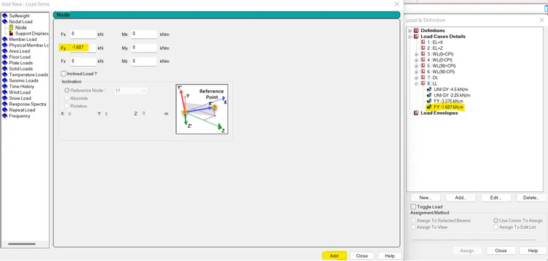
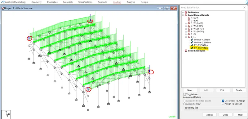
Gable frame = [0.5 X 3.375] = 1.687 KN
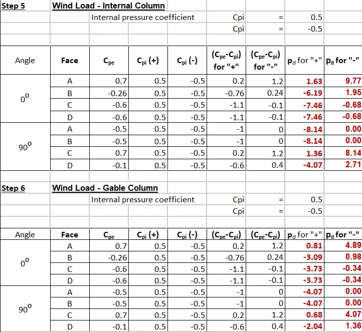
3) Calculation of wind load:-
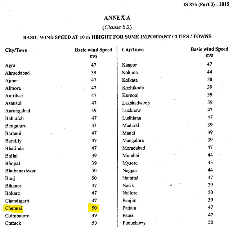
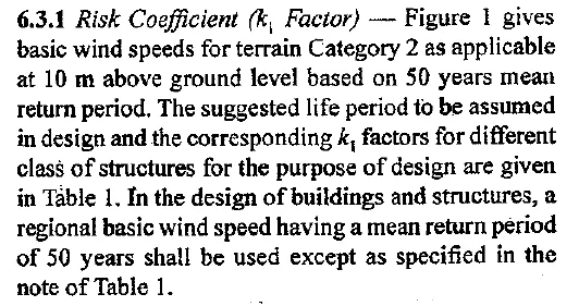
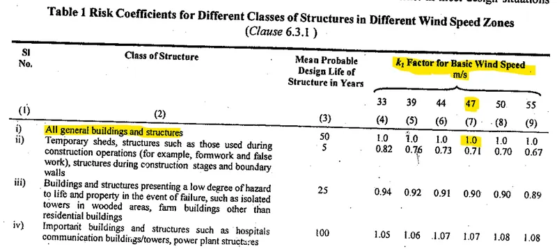
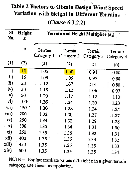
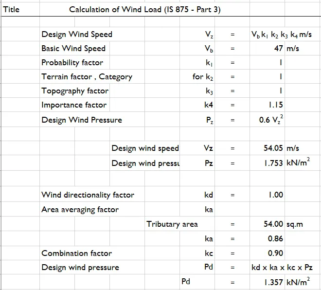
Value of K2 will be taken as 1
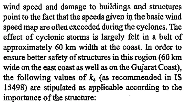
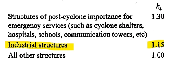
As Chennai falls under cyclonic region the value of K4 will be taken as 1.15

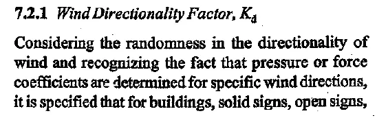
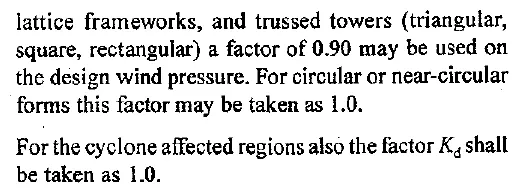
As Chennai is in the East coast of India, thus it will be considered in cyclone affected area and value of Kd = 1
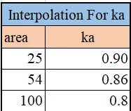
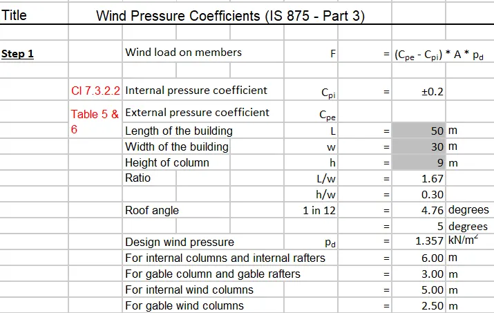
Then we calculate Tributery area as = (C/C bay distance X Height of the shed) = (6 X 9)= 54 sqm.
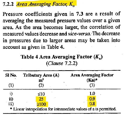
We will take the value of Ka = 0.86 by interpolation method
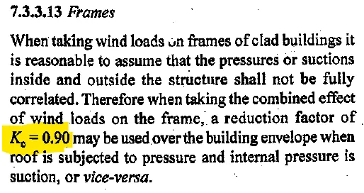
We will take the value of Kc is 0.90
4) Creation of model and assigning of property and analysing of model:-
Step-1:-
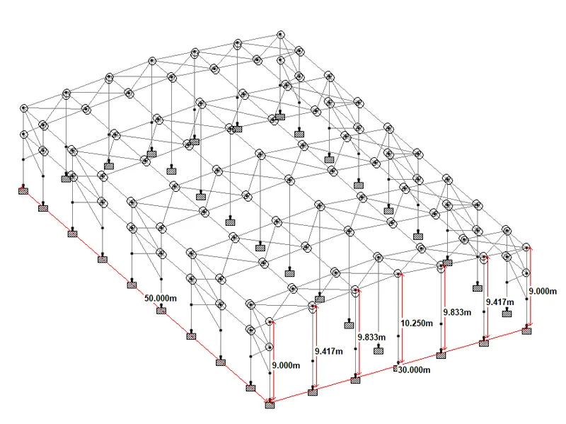
Create the same model in truss
I considered 1 in 12 slope for roof and from the calculation x= 1.45m then middle column height is (7+1.45)=8.45m
Step-2:-
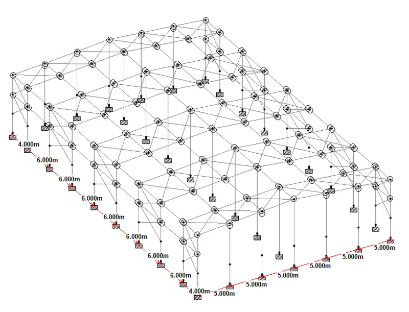
Dimensions of bay and gable column
Step-3:-
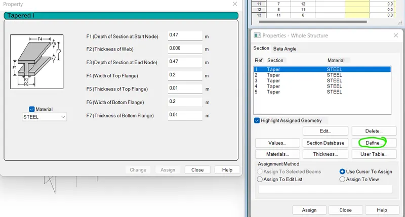
First add member properties
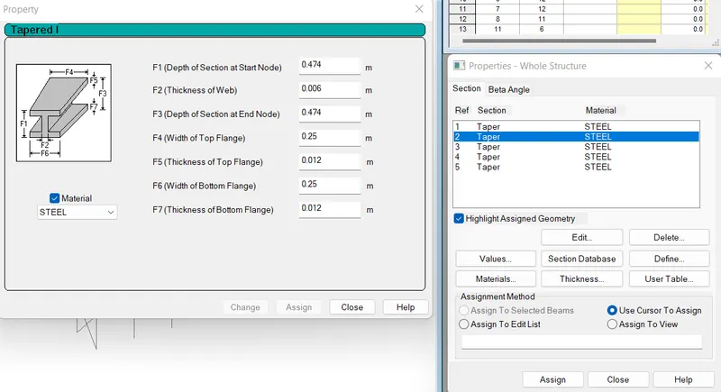
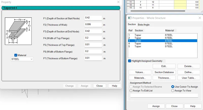
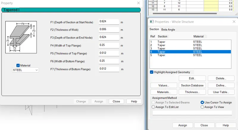
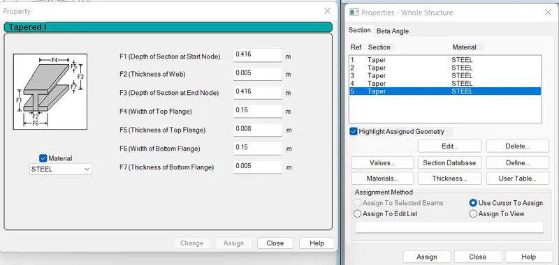
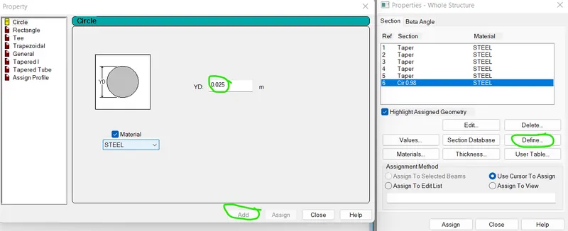
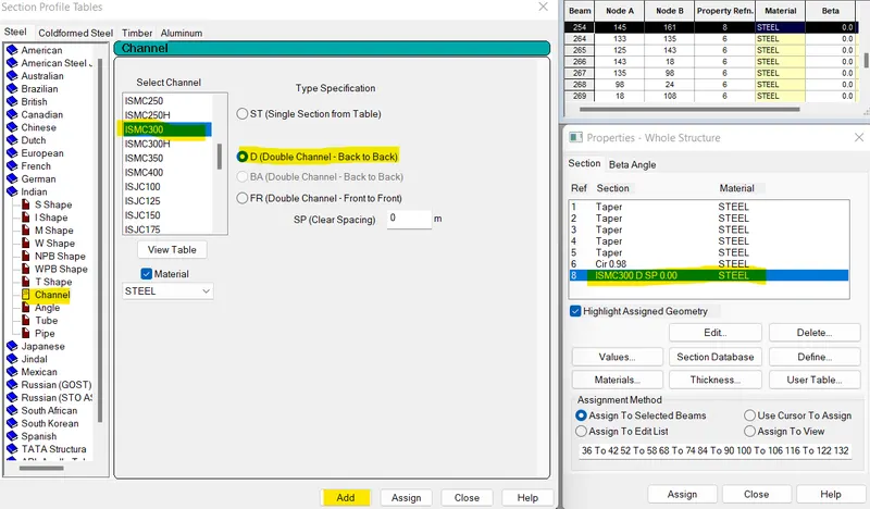
Step-4:-
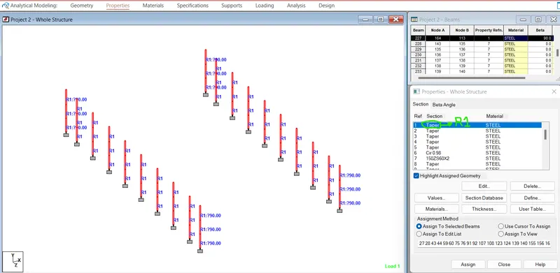
Then assign member property
For main column
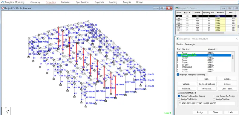
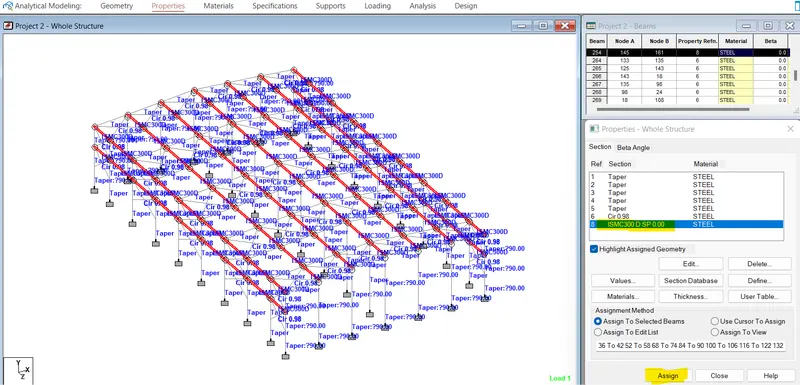
Assign property for middle column
Assign property for Gable column-
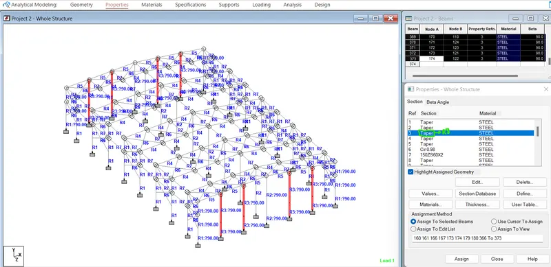
Assign member property for main Rafter-
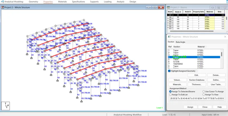
Assign material property for Gable end Rafter-
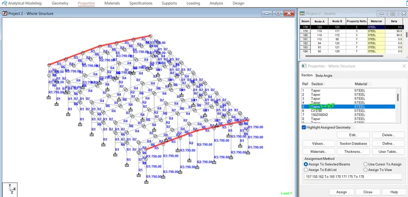
Assign bracing material property
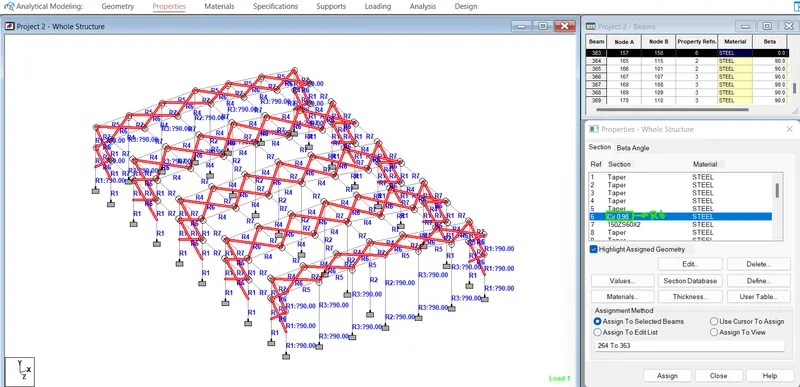
Assign purlin material property
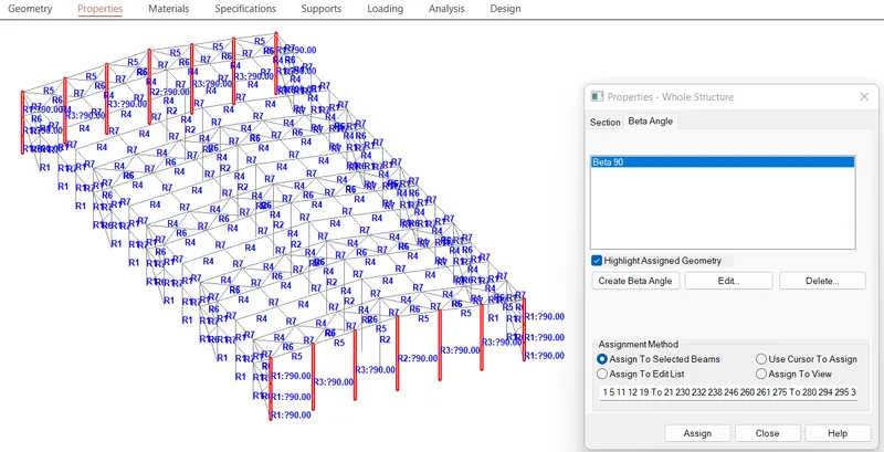
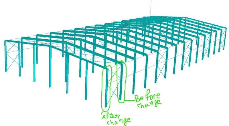
Change the beta angle for the gable end columns
Step-5:-
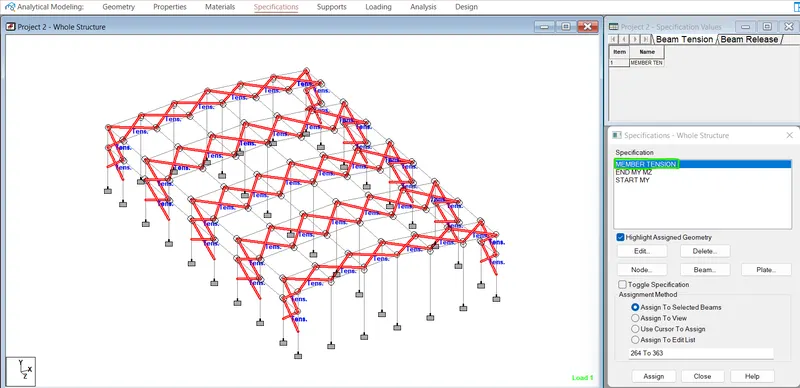
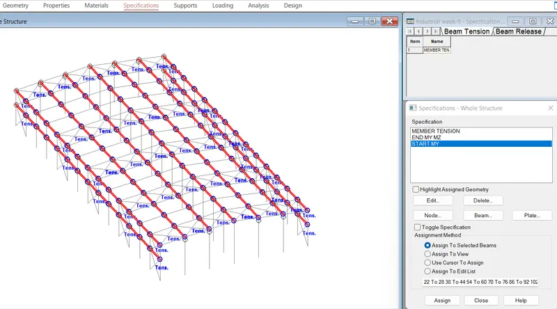
Then define bracing members as Tension member.
Go to specification tab > define beam > Tension member and assign it to all bracing members
Step-6:-
Then define release moment for end and start
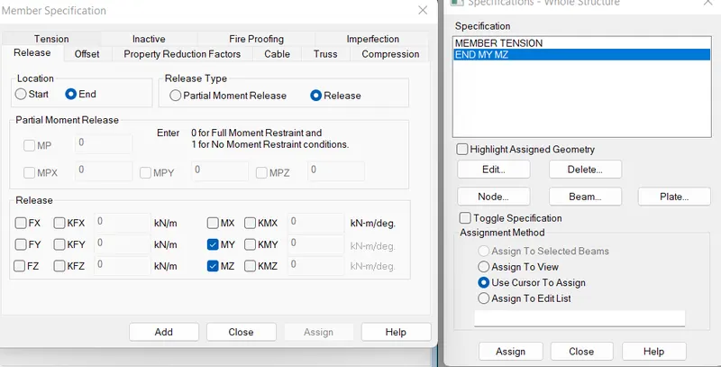
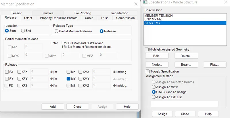
Then assign end relase to gable end columns
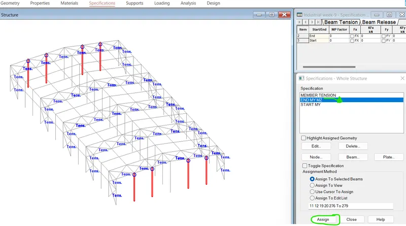
Now release the start and end moments for purlin members
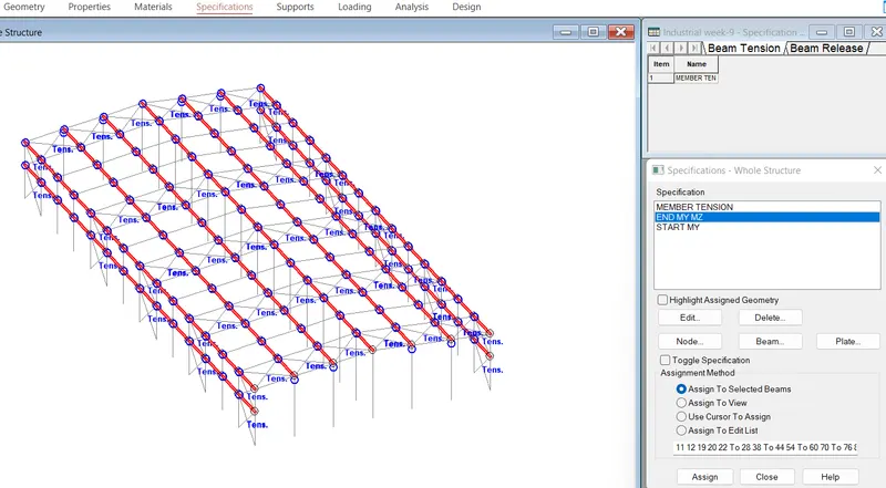
Step-7:-
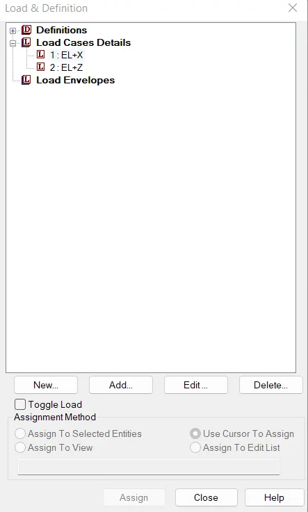
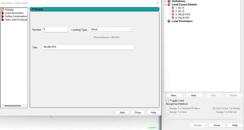
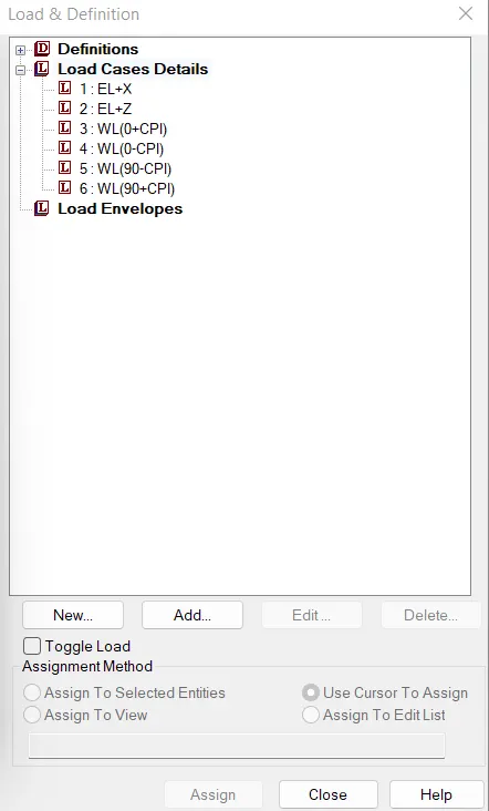
First seismic load cases in +X and +Z direction as the structure is symmetrical
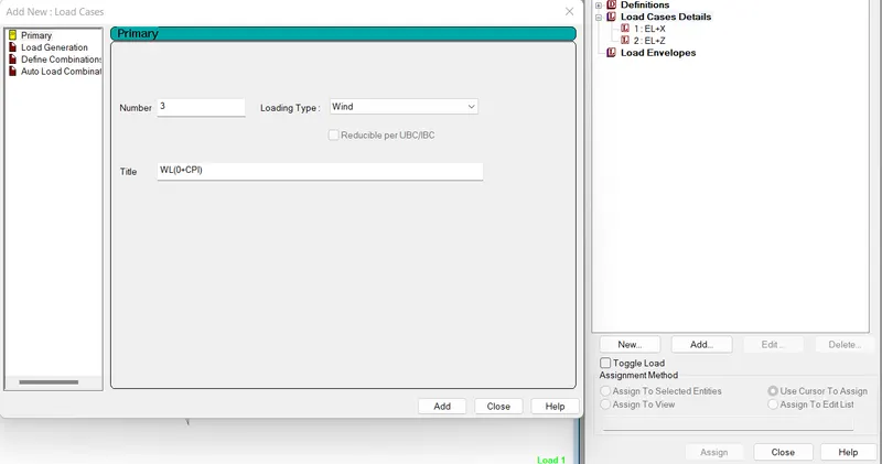
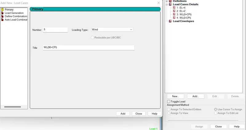
Add Wind load cases
Step-8:-
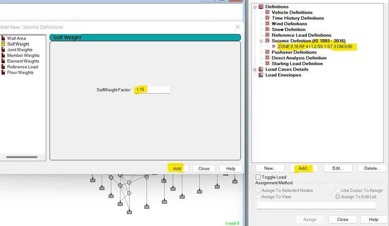
Define seismic load defination
first select the code as IS-1893-2016
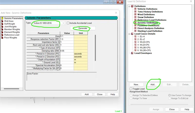
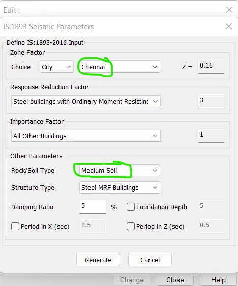
Select all the parameter as cited in the image
Step-9:-
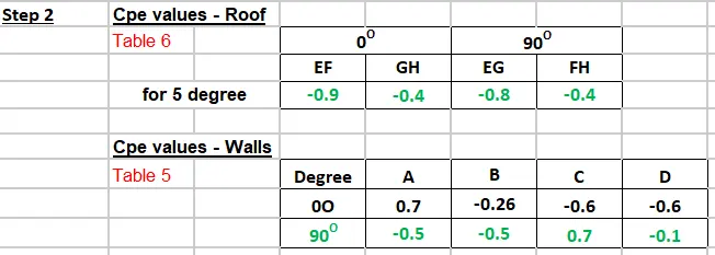
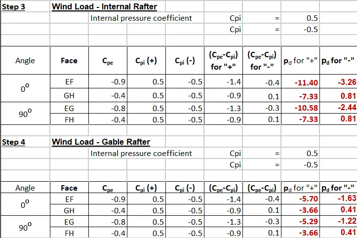
Then add WL(0+CPI) value
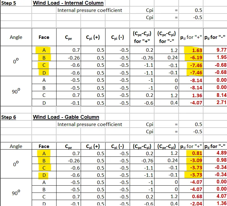
For A side main column
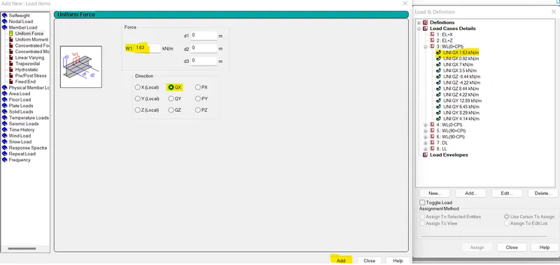
For A side Gable column
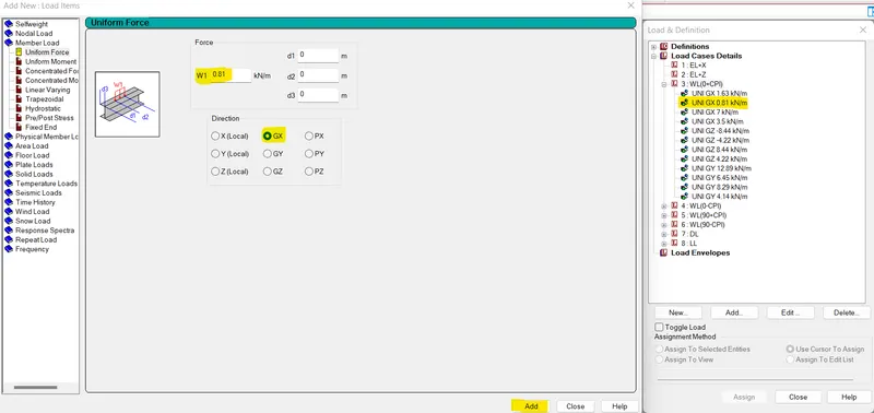
For B side Main column
For B side Gable column
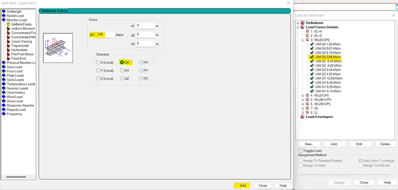
For C side main column
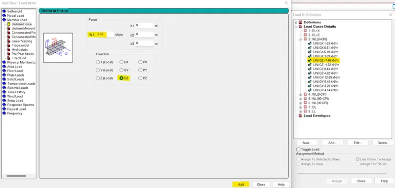
For C side Gable column
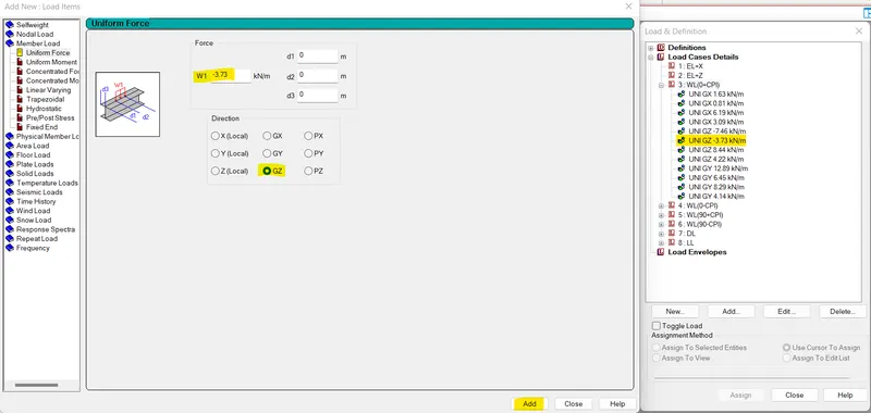
For D side main column
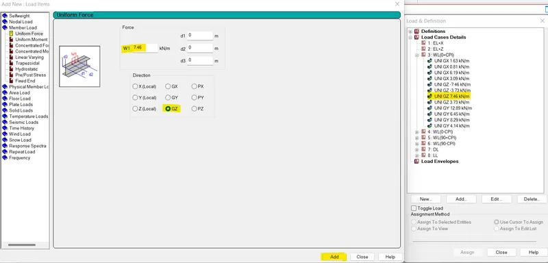
For D side Gable column
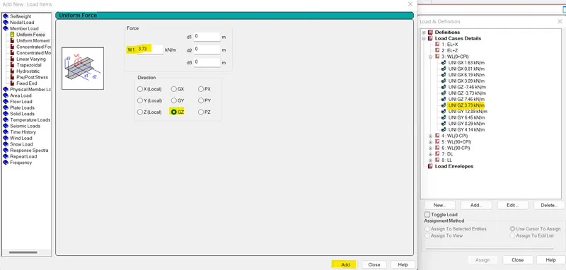
For Internal rafter and Gable rafter
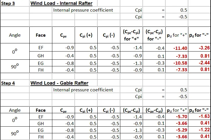
For EF side internal rafter
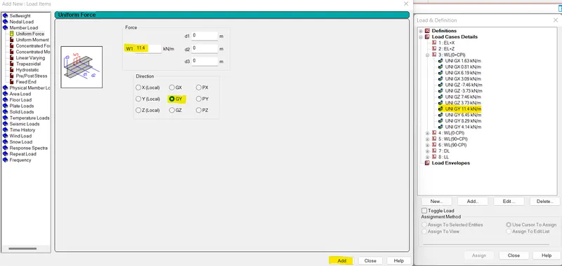
For EF side Gable rafter
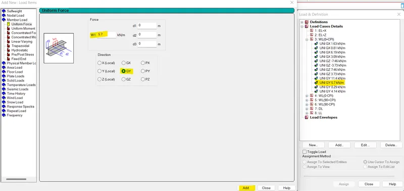
For GH side main rafter
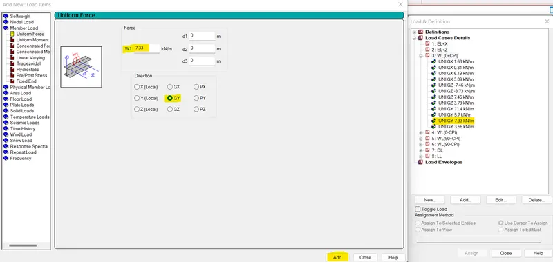
For GH side gable rafter
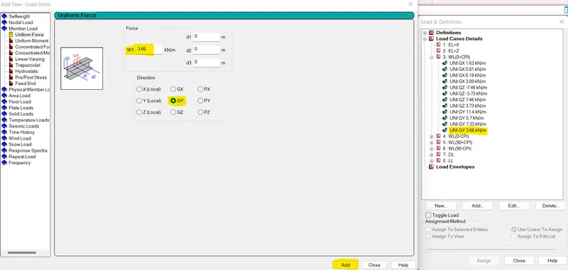
Assign wind loads in proper member
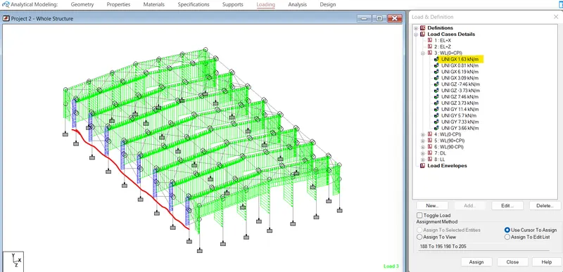
Apply force for A side main column
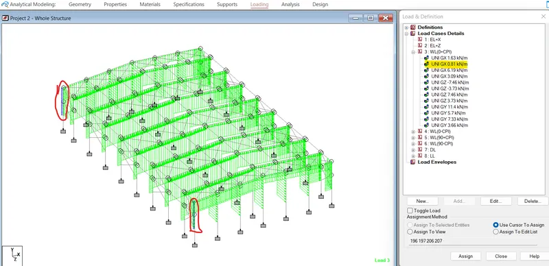
Apply wind force for A side Gable column
Apply wind force for B side main column
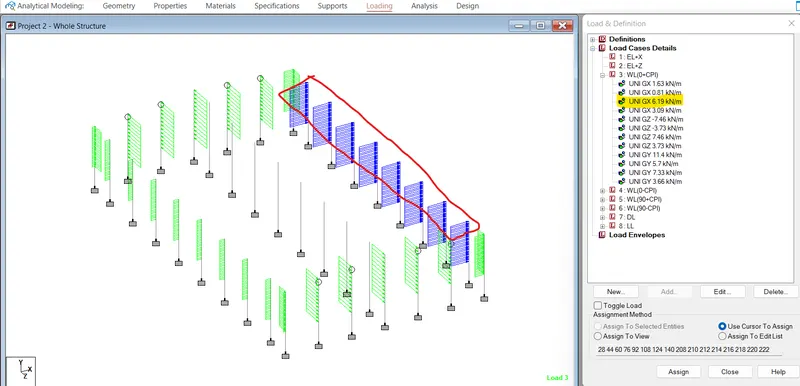
Apply wind force for B side gable column
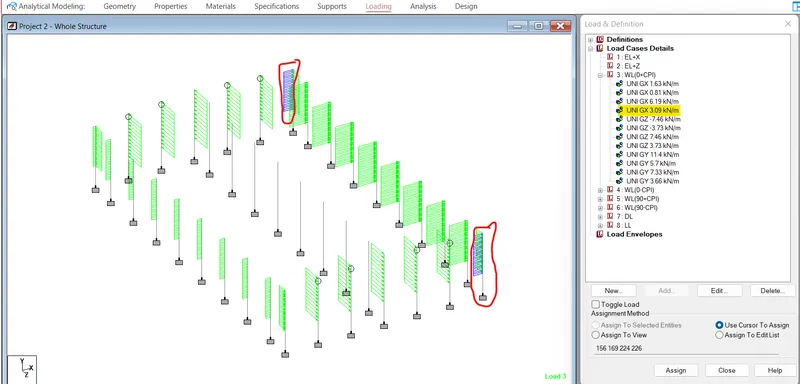
Apply wind load for C side main column
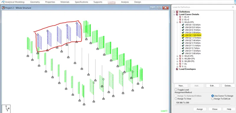
Apply wind load for C side gable column
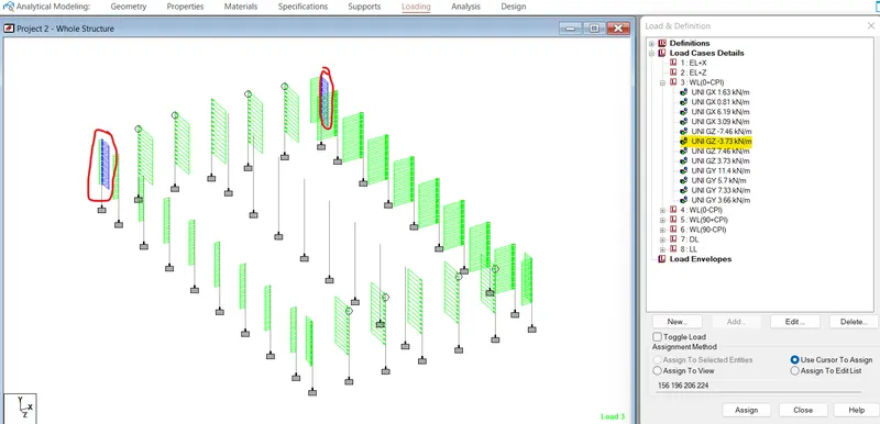
Apply wind load for D side main column
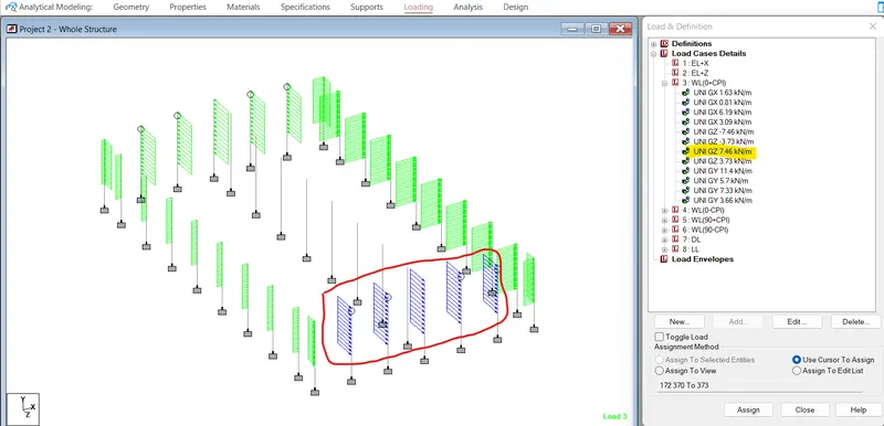
Apply wind load for D side Gable frame
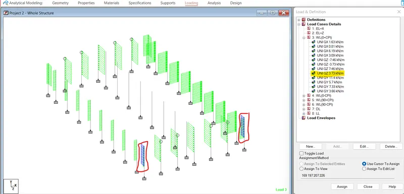
Assign the load for EF side main rafters
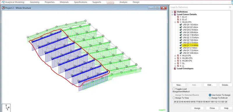
Assign load for EF side Gable Rafter
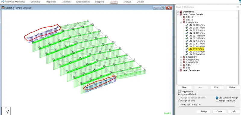
Assign wind load for GH side main Rafter
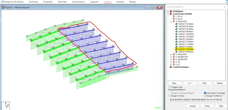
Assign wind Load for GH side gable rafter
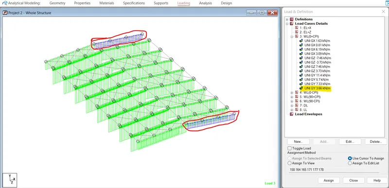
Do the same for WL(0-CPI),WL(90+CPI),WL(90-CPI) AND ASSIGN THOSE LOADS IN THE SAME MANNER
Step-10:-
Add load cases for dead load & live load
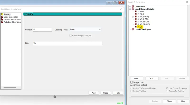
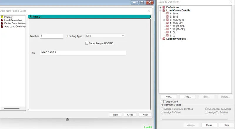
Step-11:-
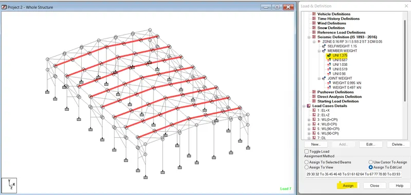
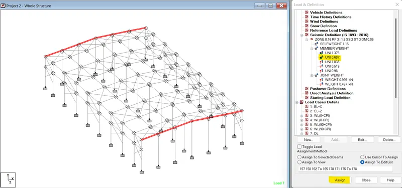
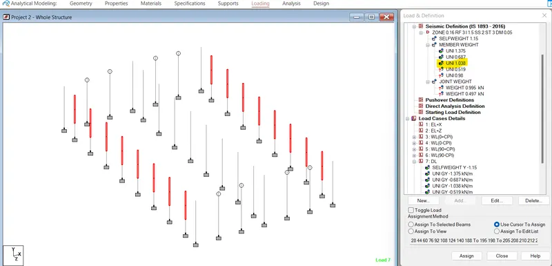
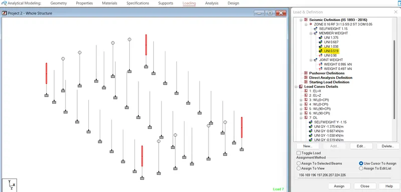
Add different loads under Dead load case
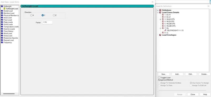
Then assign it to the whole view
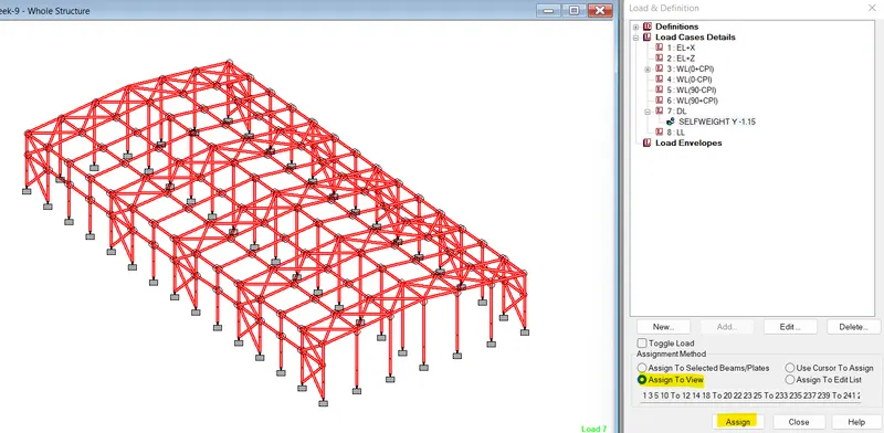
Add another member load cases under dead load
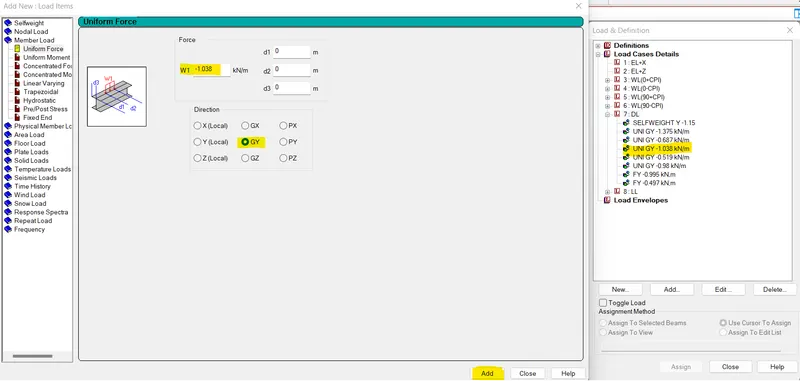
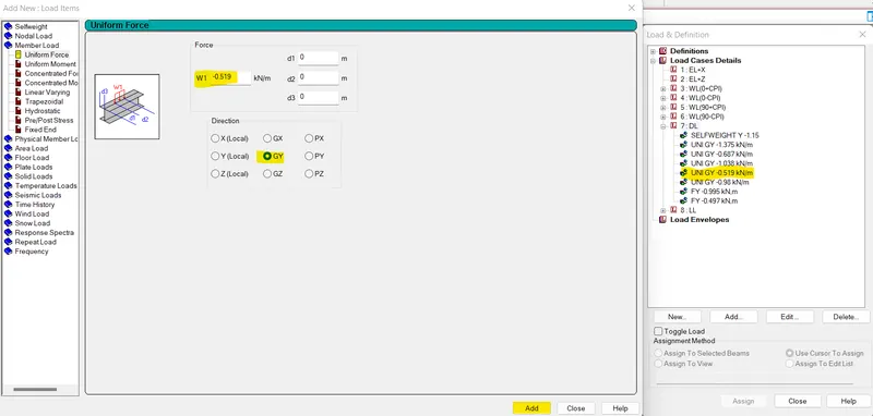
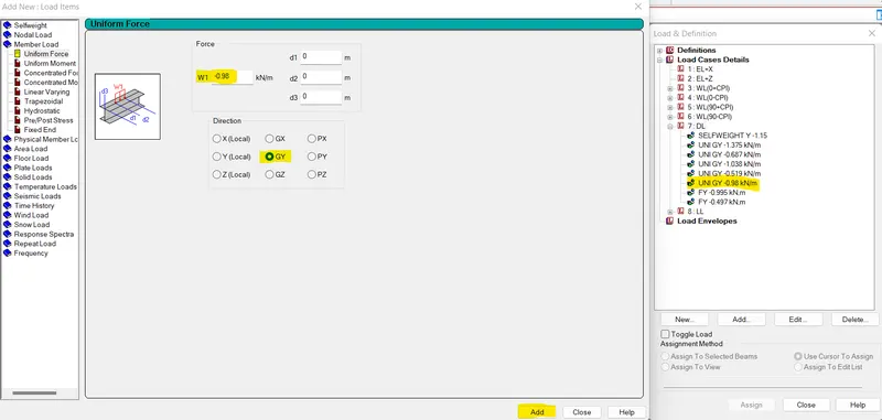
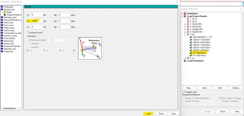
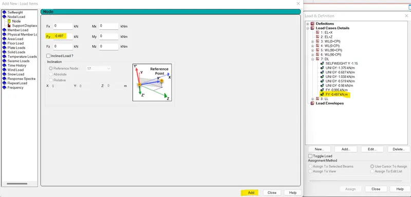
Step-12:-
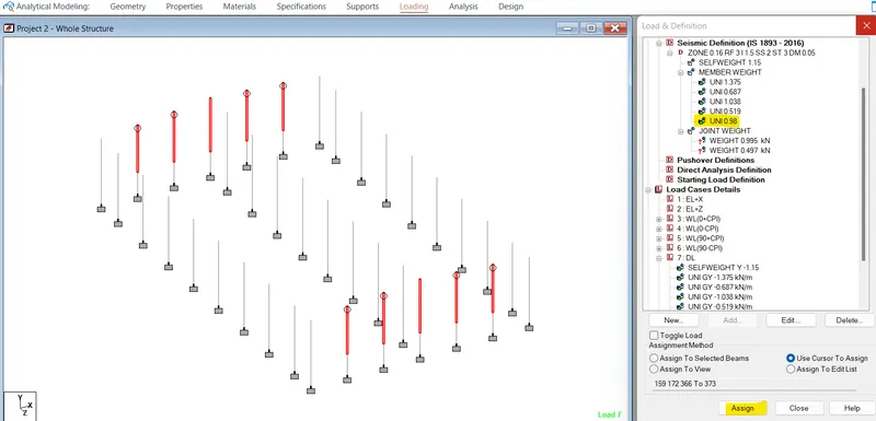
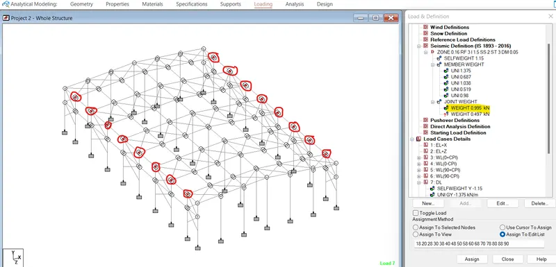
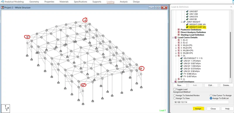
Assign dead loads to the members accordingly
Step-13:-
Define live loads under live load case.
Step-14:-
Assign live loads under live load case.
Step-15:-
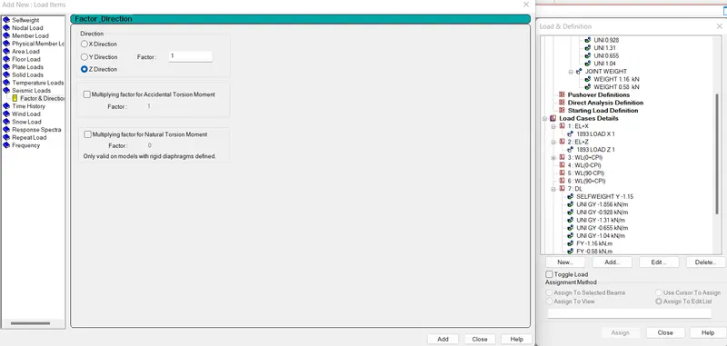
Add seismic load values under seismic load case
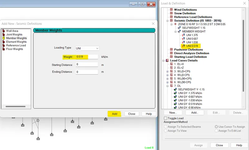
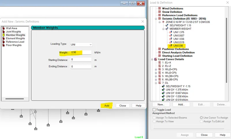
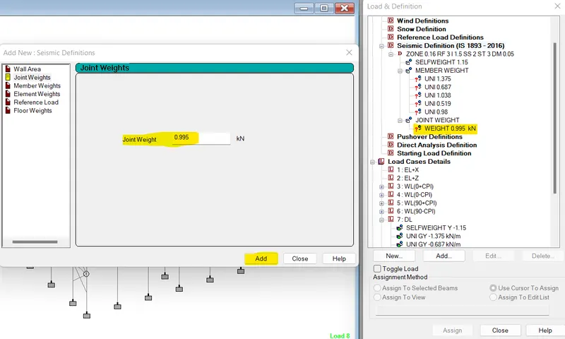
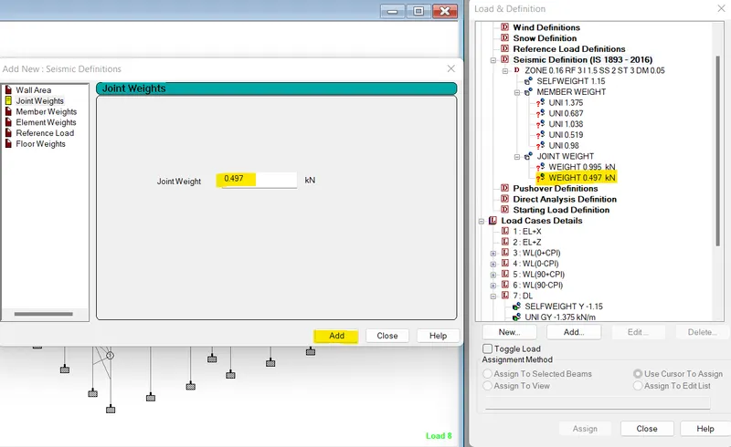
Step-16:-
Assign seismic load values under seismic load case.
Step-17:-
Add seismic load under seismic load cases
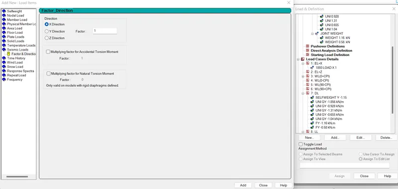
Step-18:-
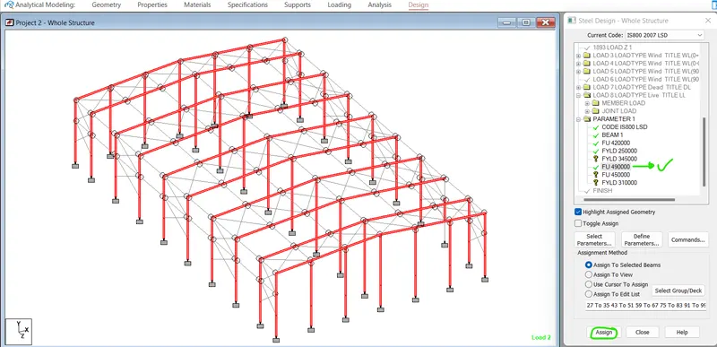
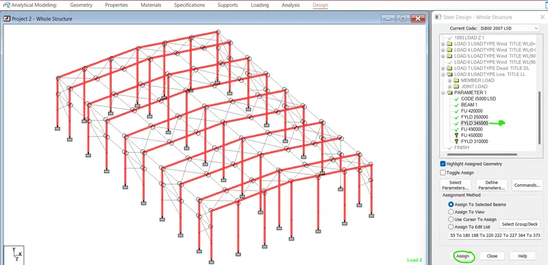
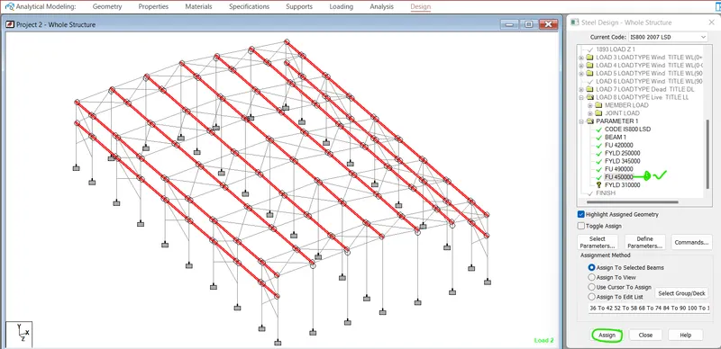
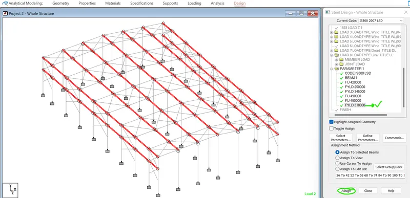
Selection of design parameters
Go to design tab and select steel design code.
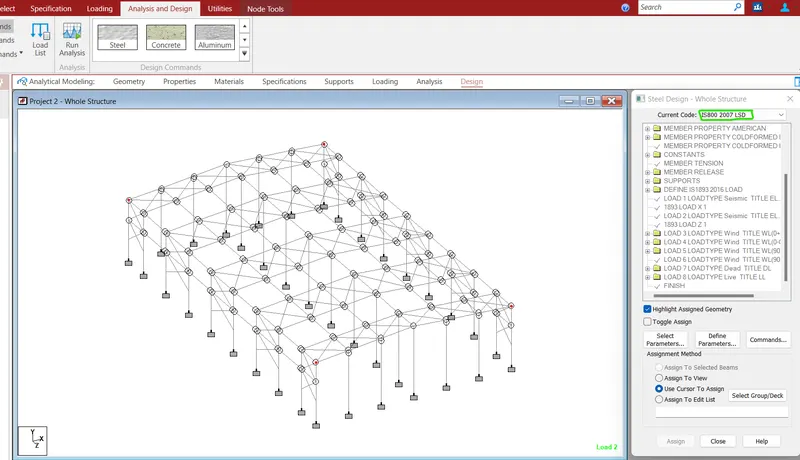
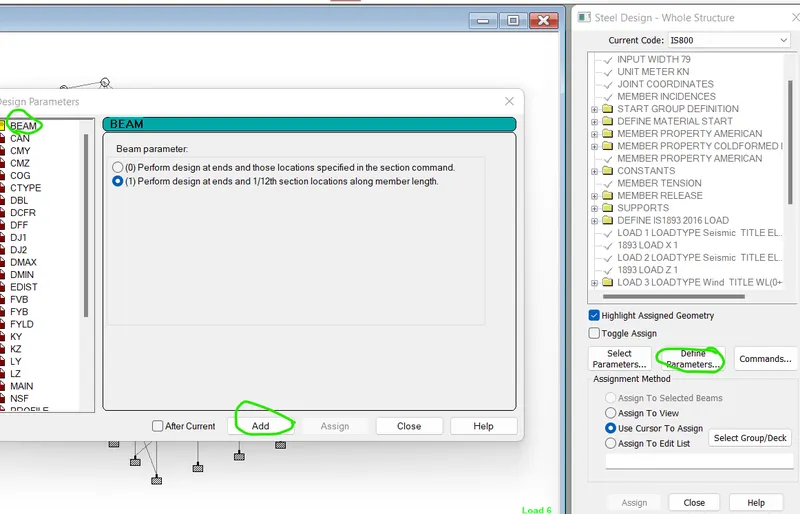
Then define design parameters
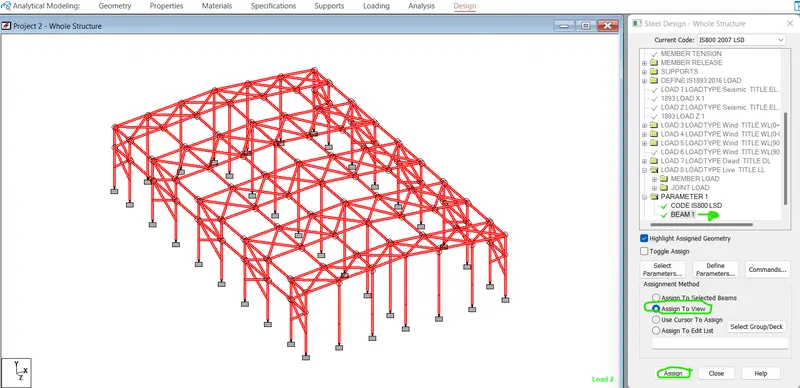
After that assign the beam property to the whole view
Define other parameters
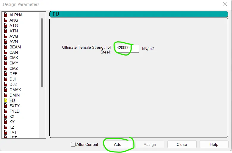
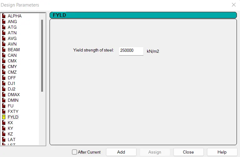
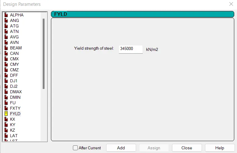
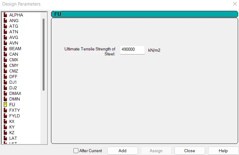
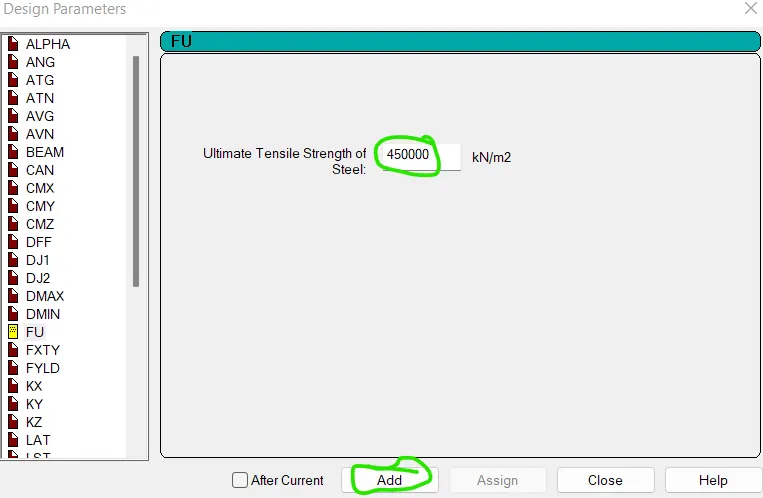
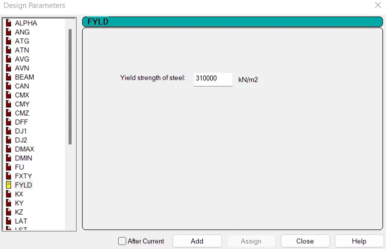
Assign those parameters accordingly
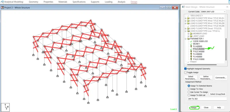
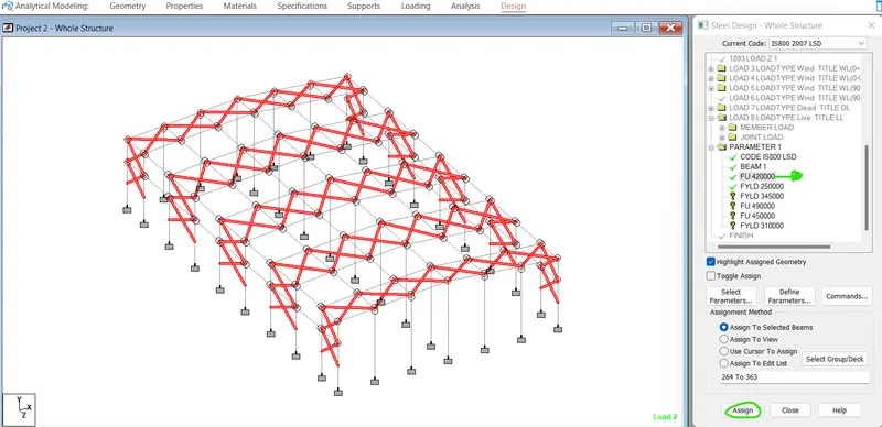
Step-19:-
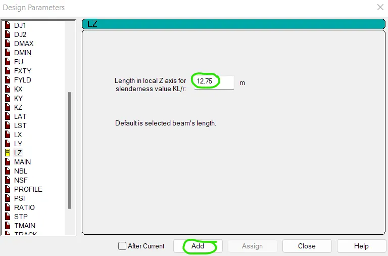
Define and assign Kx,Ky,Kz for Rafter members
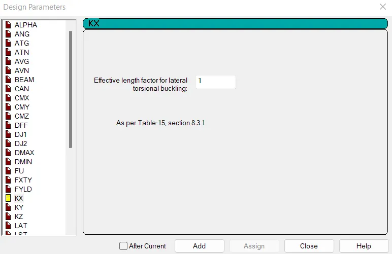
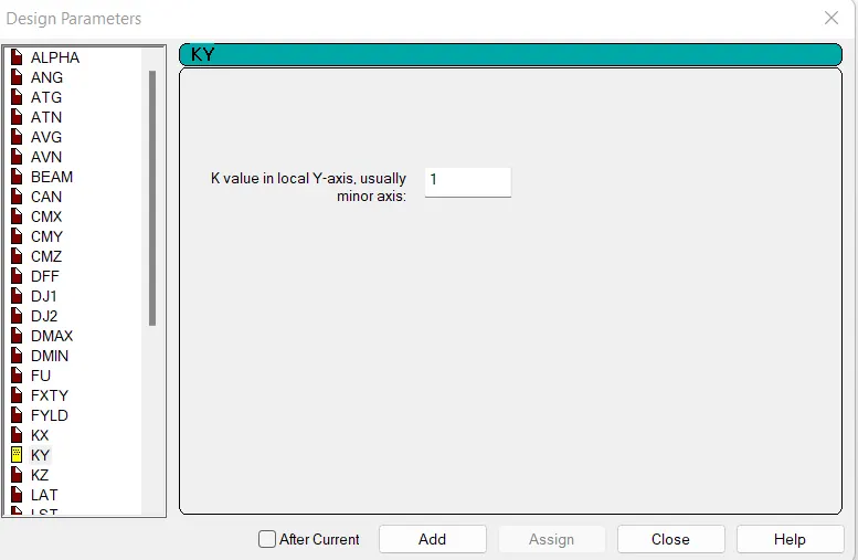
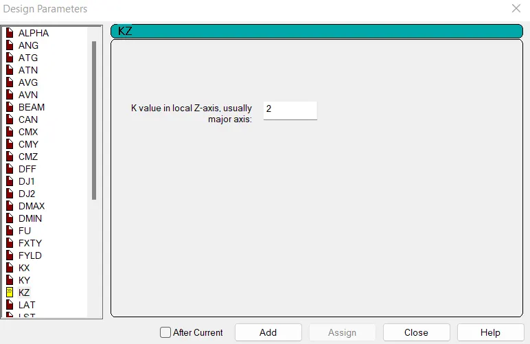
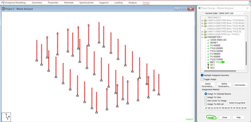
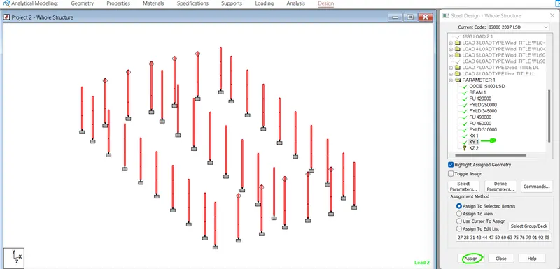
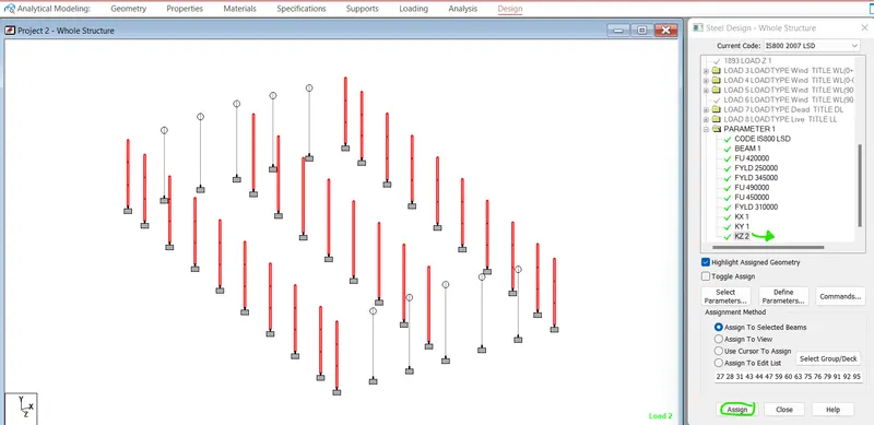
Define Lx,Ly,Lz values
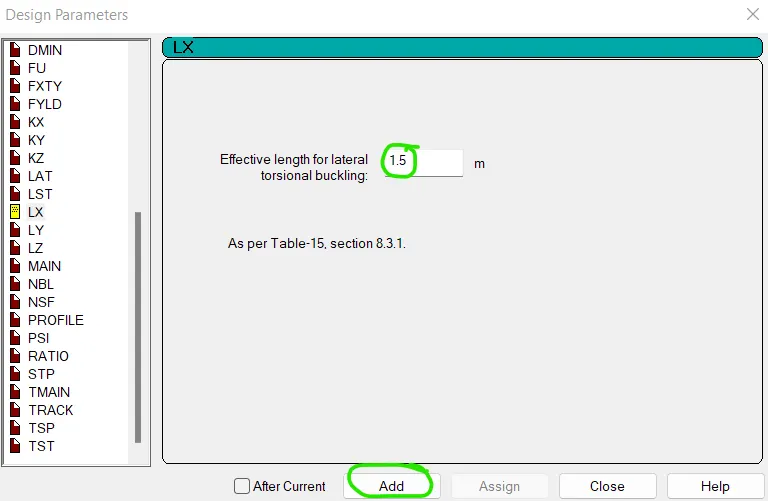
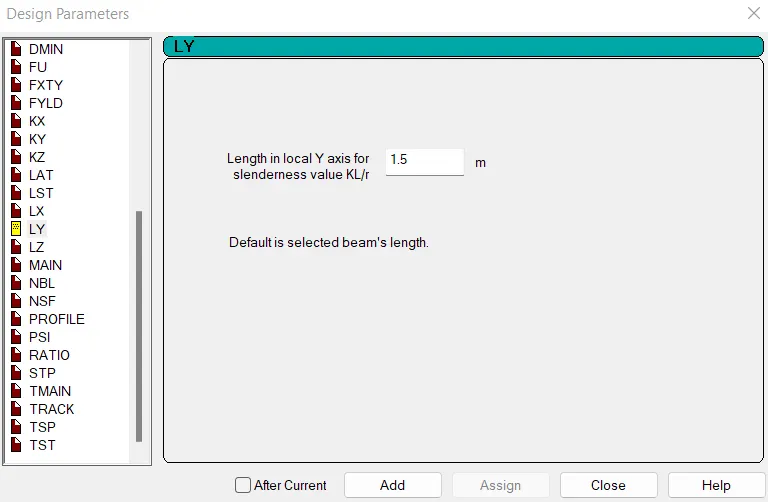
Add Lz value as 0.85 times of width of the building width = (15X0.85)=12.75
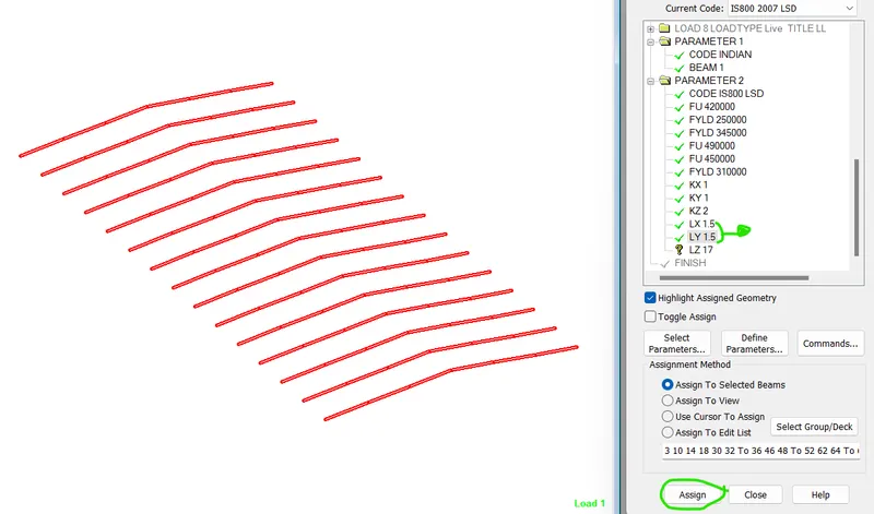
Assign Lx and Ly values to all Rafters
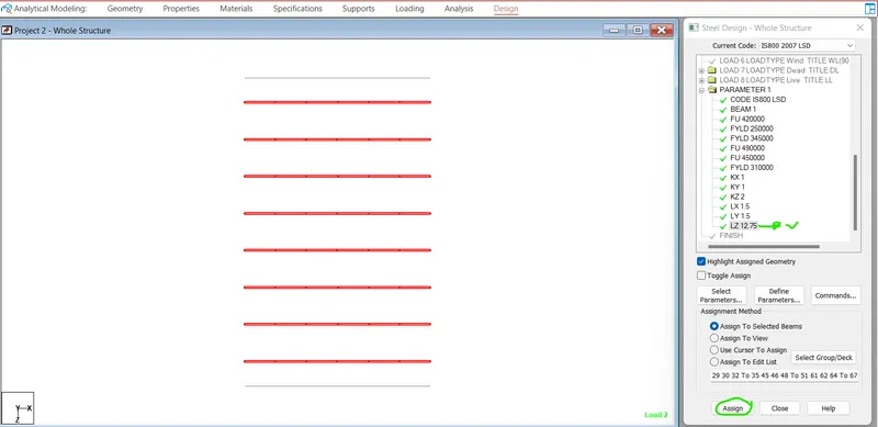
Assign Lz value to gable main rafters
Step-20:-
Define and assign Lx,Ly,Lz for Column members
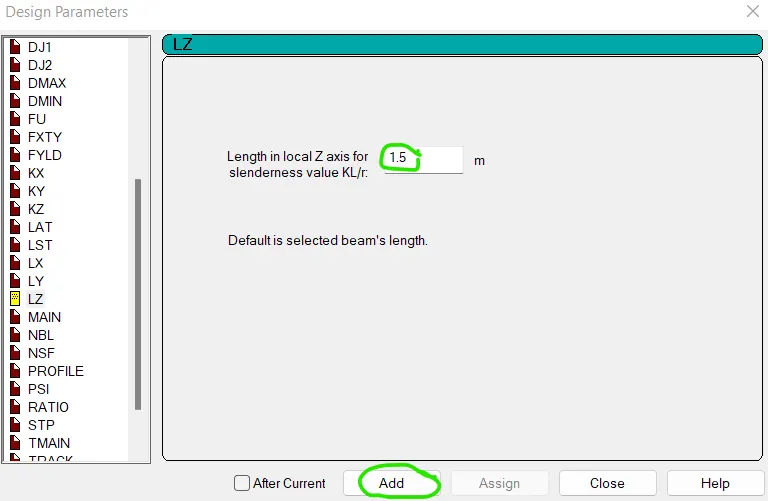
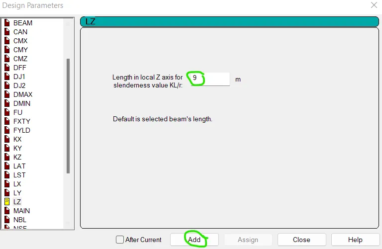
Assign Lx for all main columns except internal middle columns
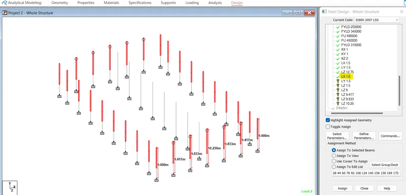
Assign Ly for all main columns except internal middle columns
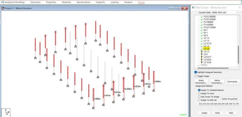
Assign Lz value of 1.5 for corner columns above 3m because of brickwall
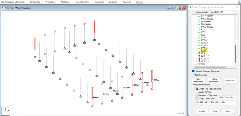
Now assign Lz =9 for main frame corner columns
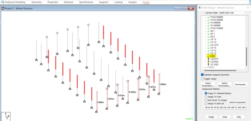
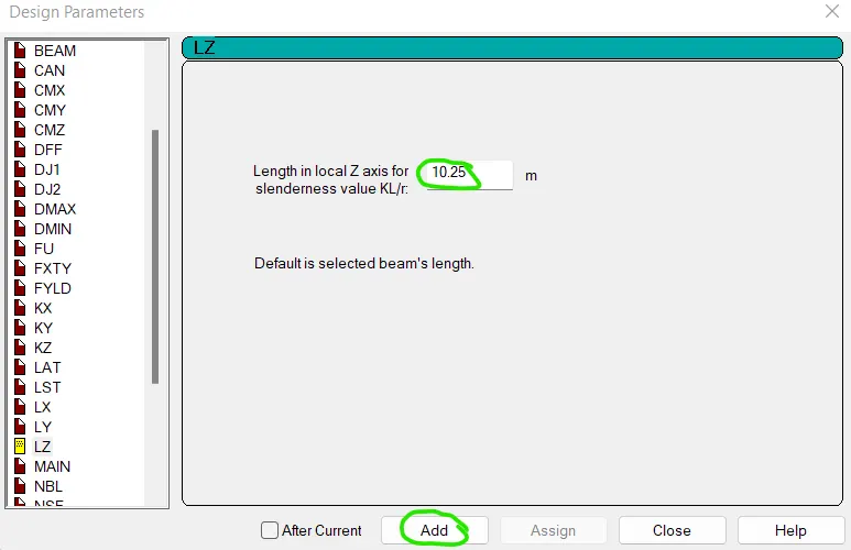
Now assign Lz= 10.25 for gable end central column
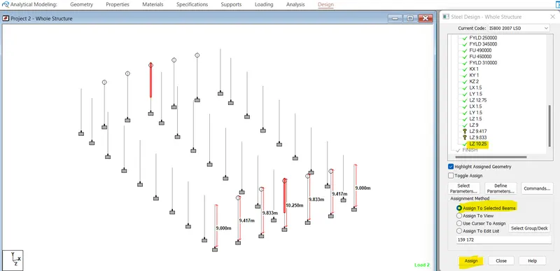
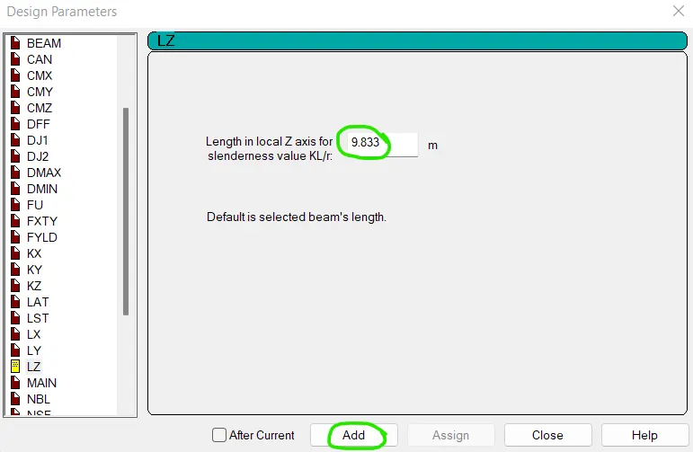
Assign Lz= 9.833
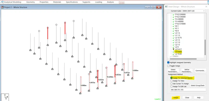
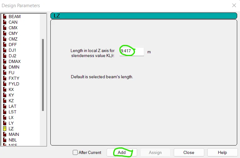
Assign Lz=9.417
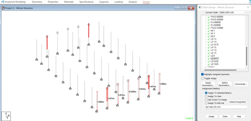
Step-21:-
Define slenderness limit as 180.
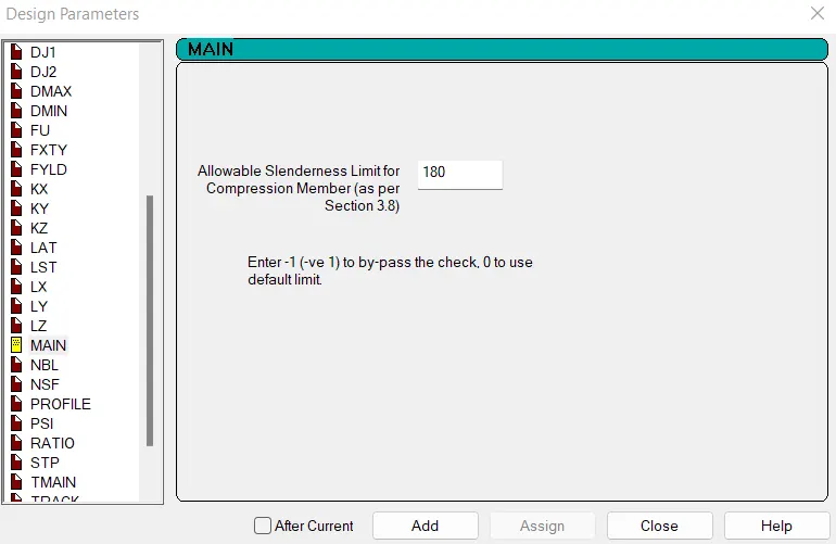
Assign this to all columns
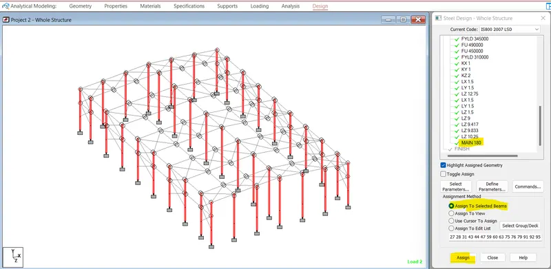
Define Ratio as 1
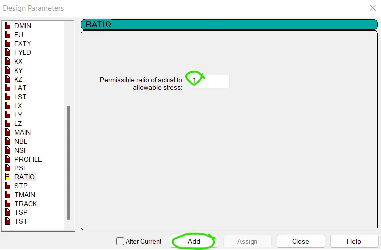
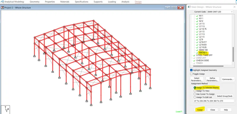
Assign ratio 1 to the structure except bracings
Step-22:-
Define design command
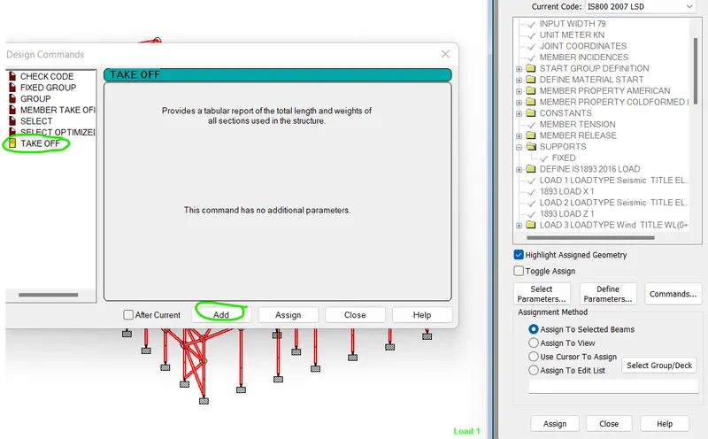
Assign take off to the entire view
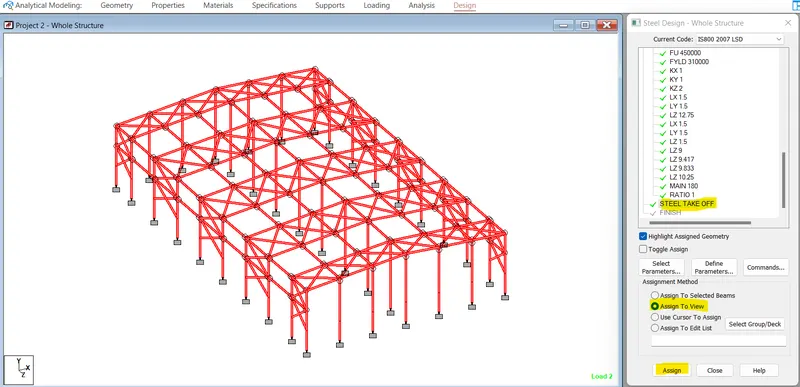
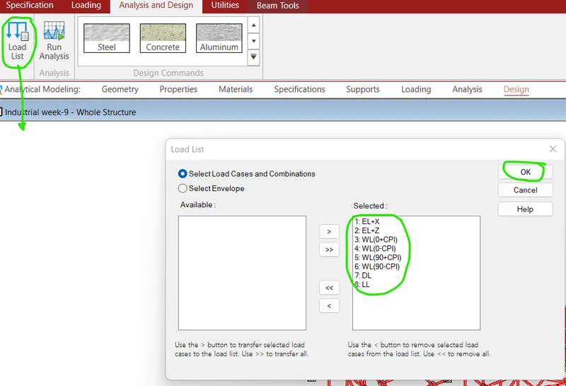
Go to Analysis and design tab and then add Load list
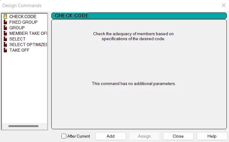
Go to define commands and add check code
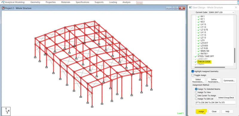
Assign check code to structure except bracings
Step-23:-
Remove other parameters tab there should be only one parameter
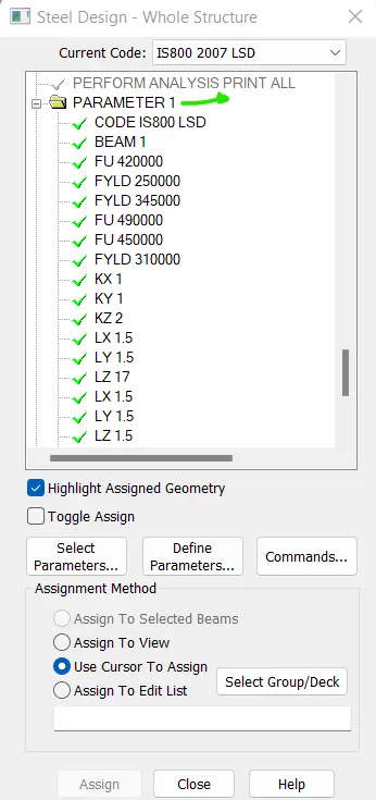
Step-23:-
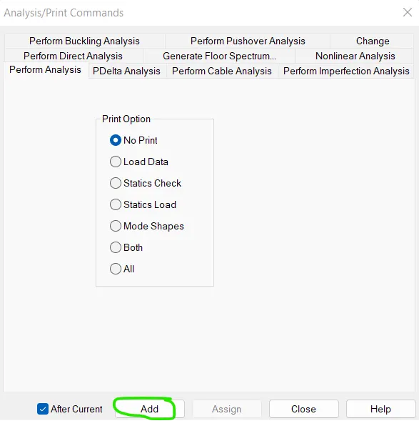
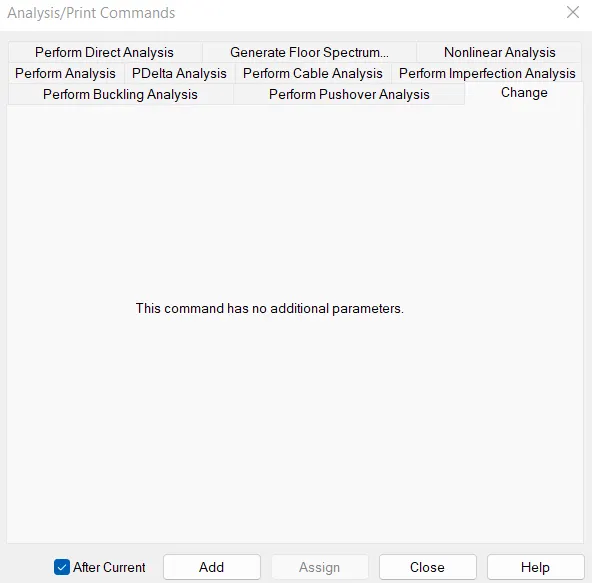
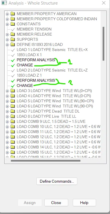
Add perform analysis and change command after each seismic load case and tick after current option.
Step-24:-
Define load combination
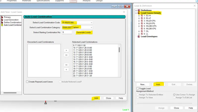
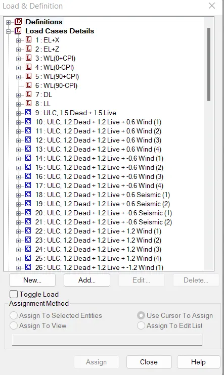
Step-25:-
Run the analysis and go to Post processing mode
Step-26:-
Design basis report
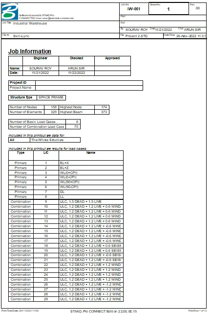
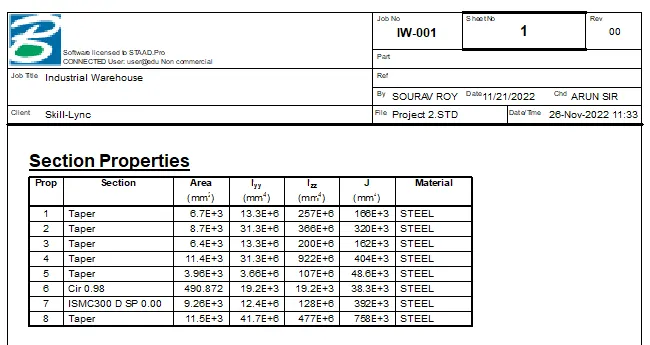
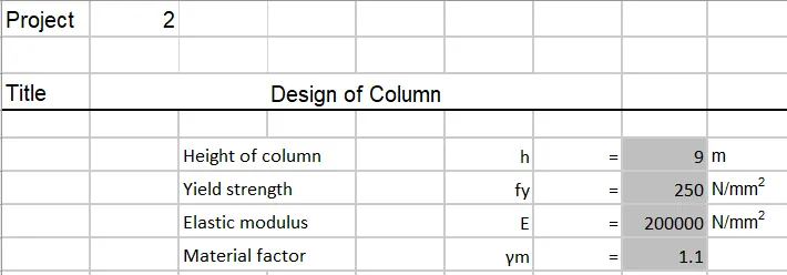
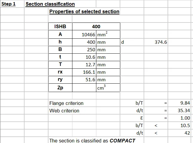
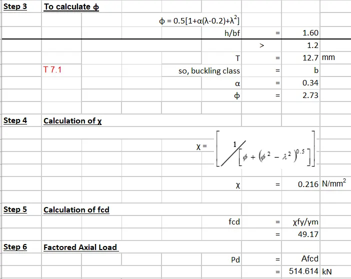
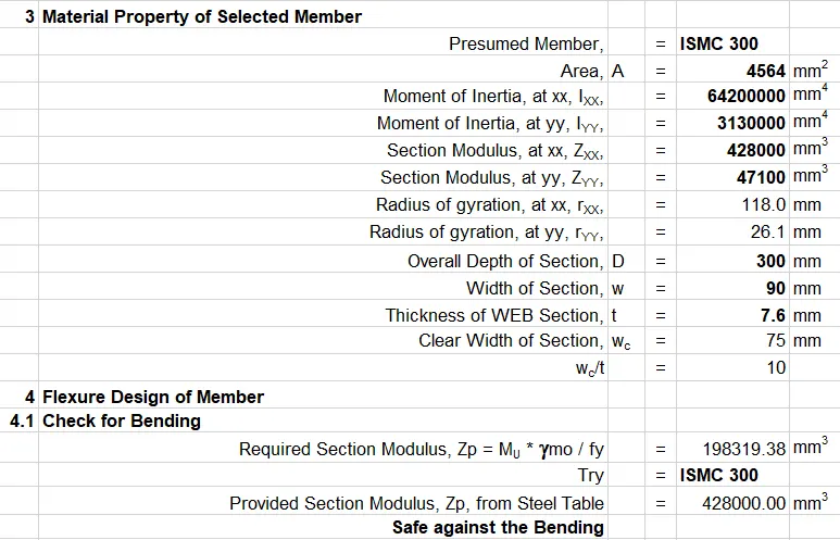
5) Design of Steel Column member in MS-Excel:-

6) Design of Steel Rafter in MS-Excel:-
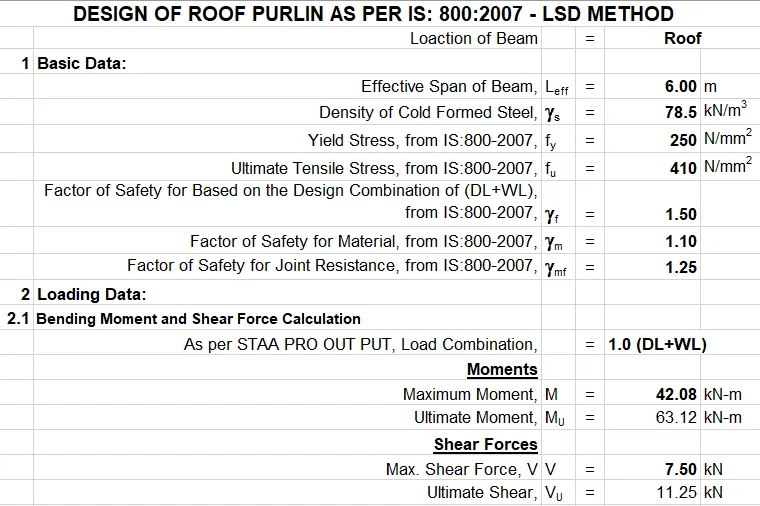
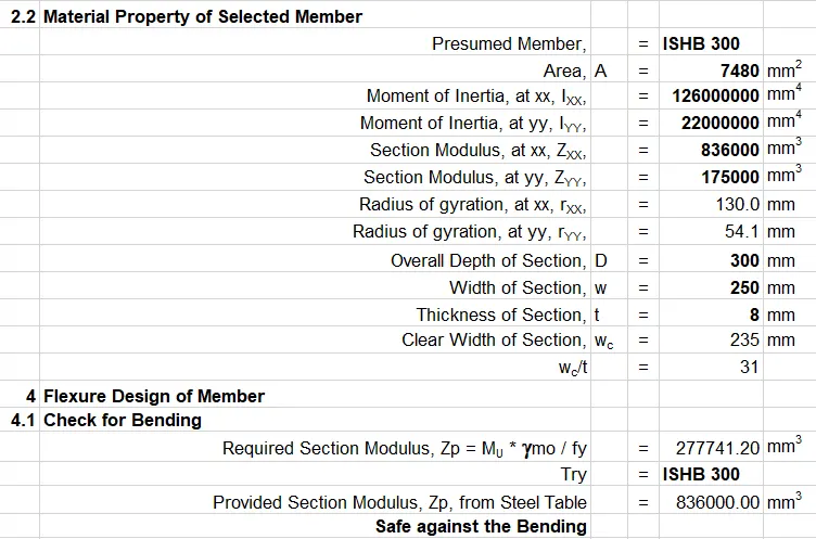
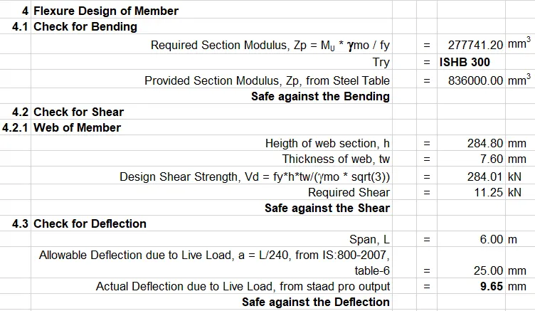
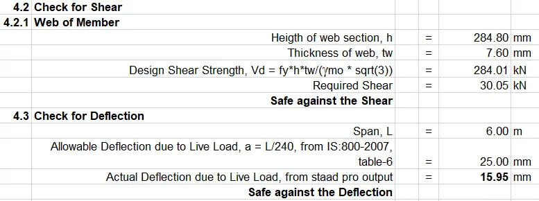
7) Design of Steel purlin in MS-Excel:-
8) Design of base plate in MS-Excel:-
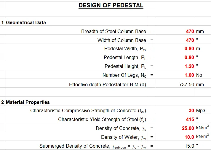
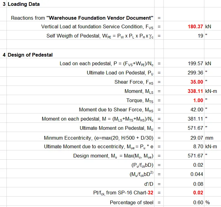
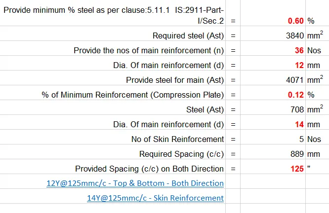
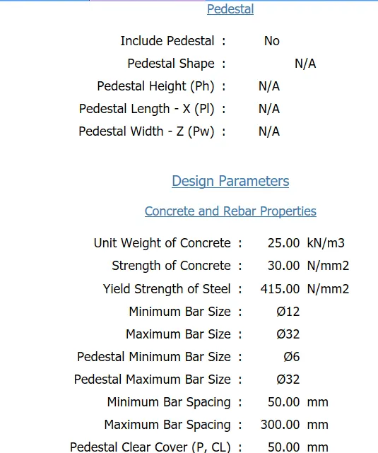
9) Design of Pedestral in MS-Excel:-
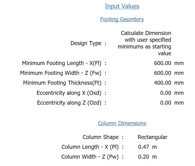
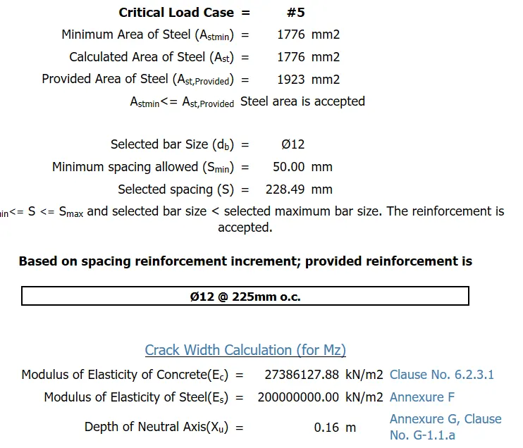
10) Design Foundations using STAAD Foundation:-
Step:-1
i) Open the model
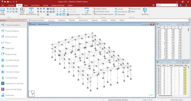
ii) Click on Staad Foundation
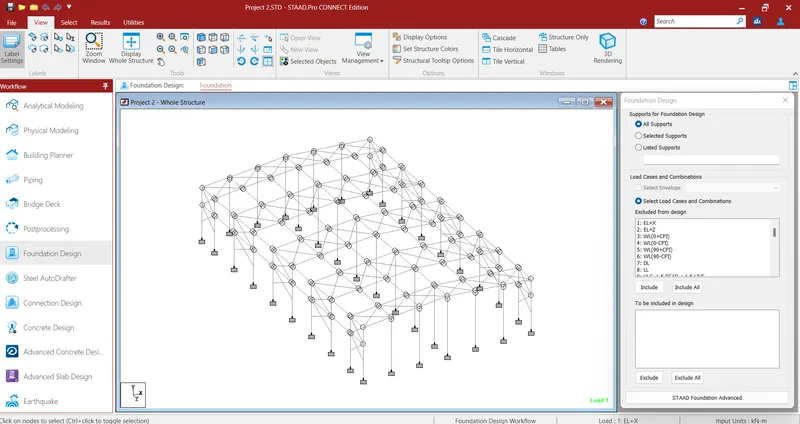
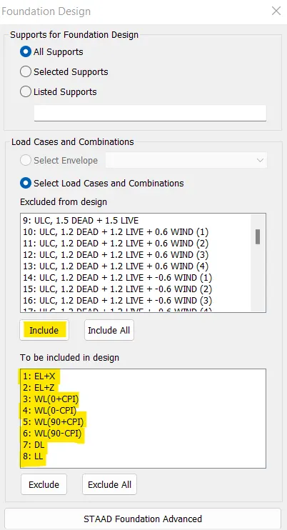
Include only Prime load cases
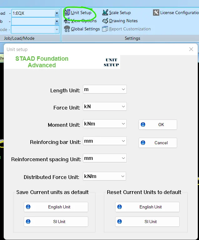
Step:-2
i) Set the unit system
Step:-3
Generate Service and ultimate Load combination
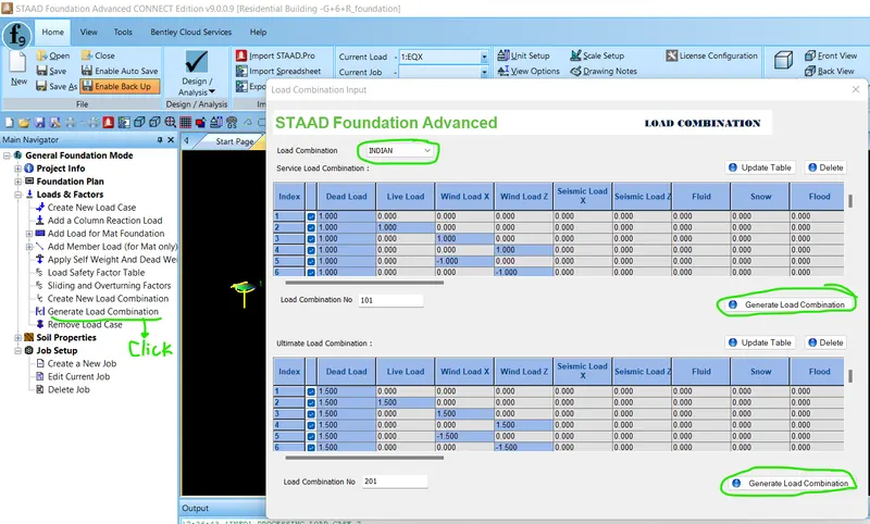
Then click to column reaction load
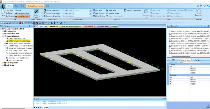
iii) Create a Job
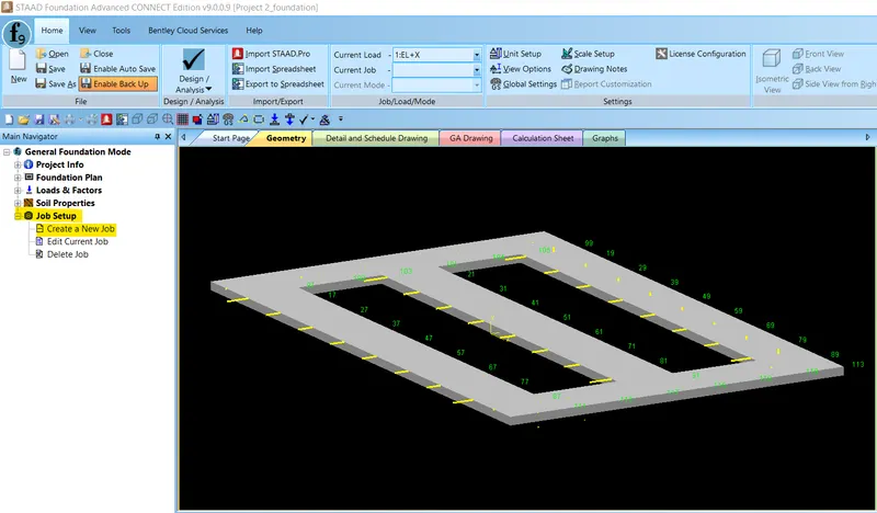
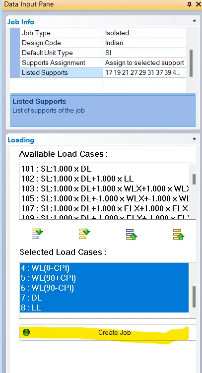
Then click to create job logo.
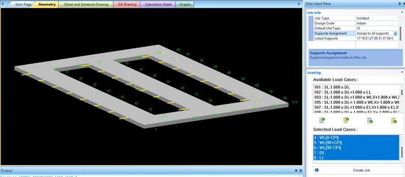
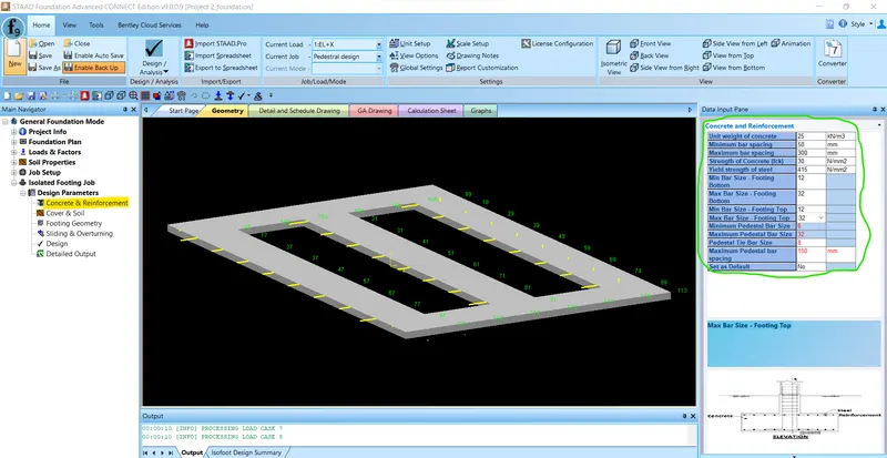
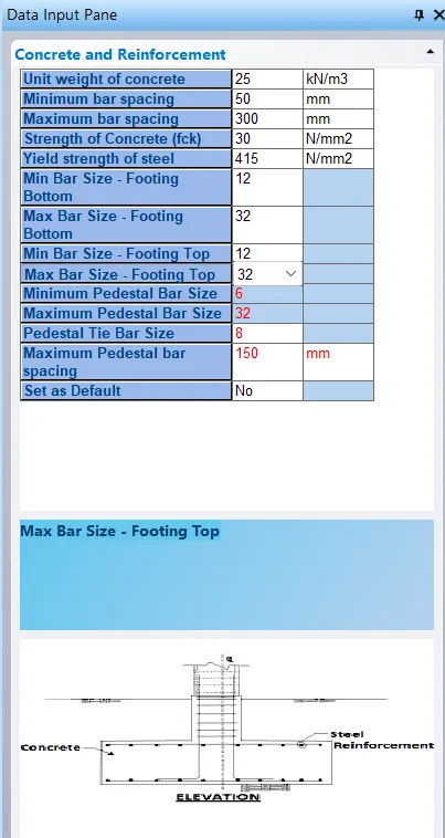
iv) Enter concrete and reinforcement details
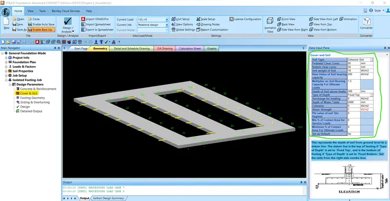
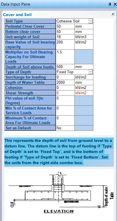
v) Enter Soil property
vi) Enter Footing Geometry
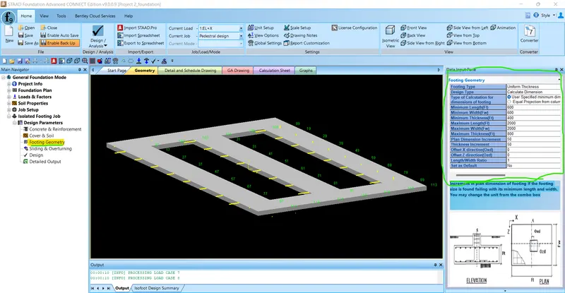
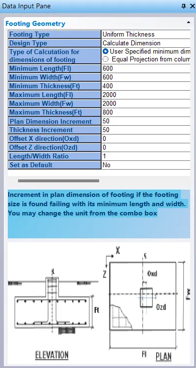
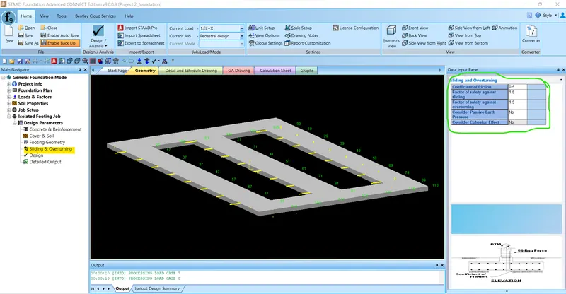
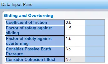
vii) Provide sliding & overturning data
vi) Click on Design
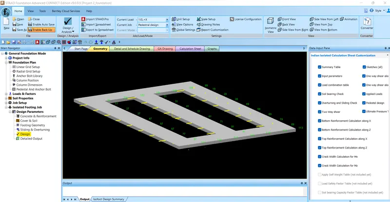
vii) Once design is completed you will see the details of footing
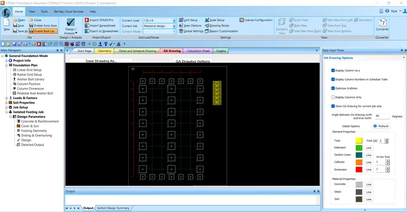
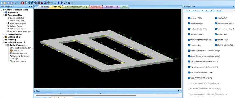
viii) Design output of footing
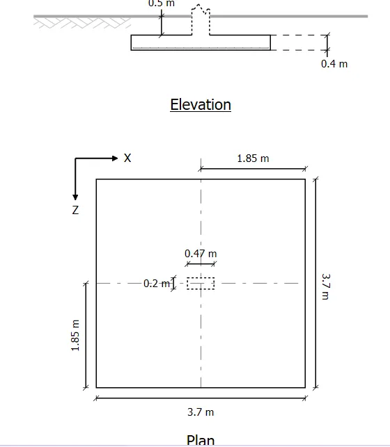
Result:-
The Design of a Warehouse Building (Steel building) is successfully completed. Also following criteria of the question is successfully answered.
- Prepare a Design Basis Report for the project
- Create structural model using STAAD Pro Connect Edition
- Prepare DL, LL, WL and EQL load calculations as per IS 875 standards
- Design of steel column using MS-excel.
- Design of rafter using MS-excel.
- Design of base plate using MS-excel.
- Design of pedestral using MS-excel.
- Design of purlin using MS-excel.
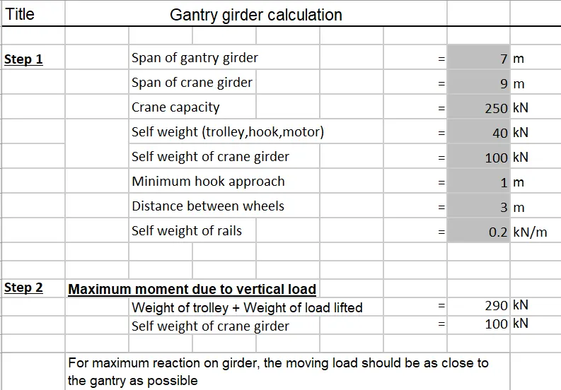
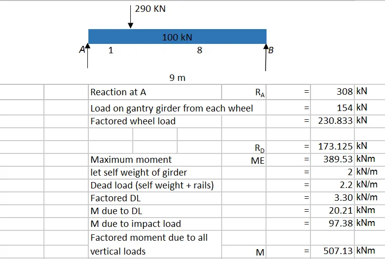
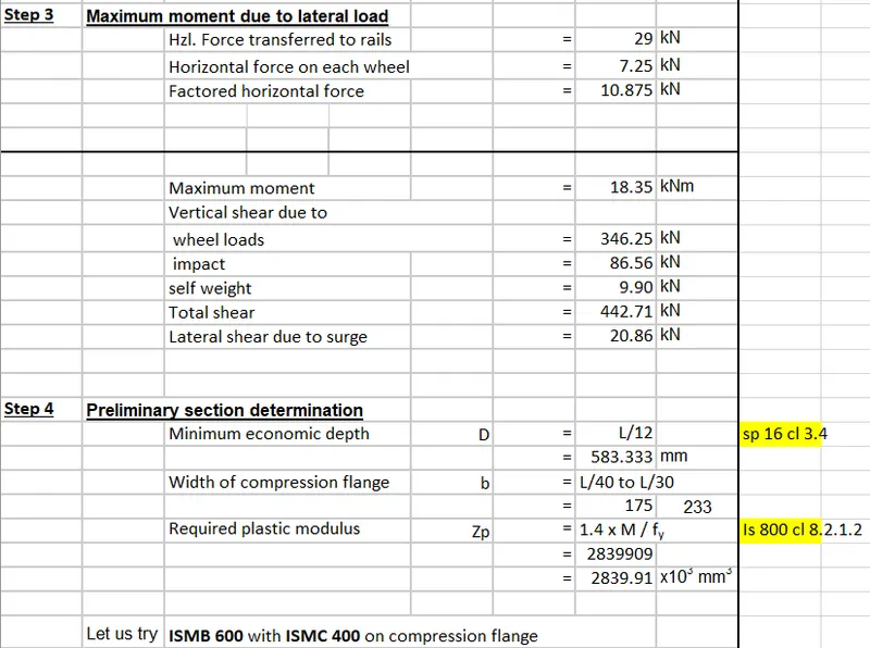
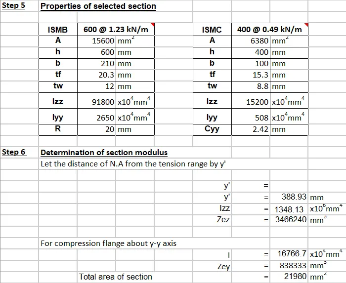
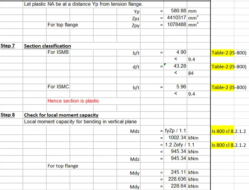
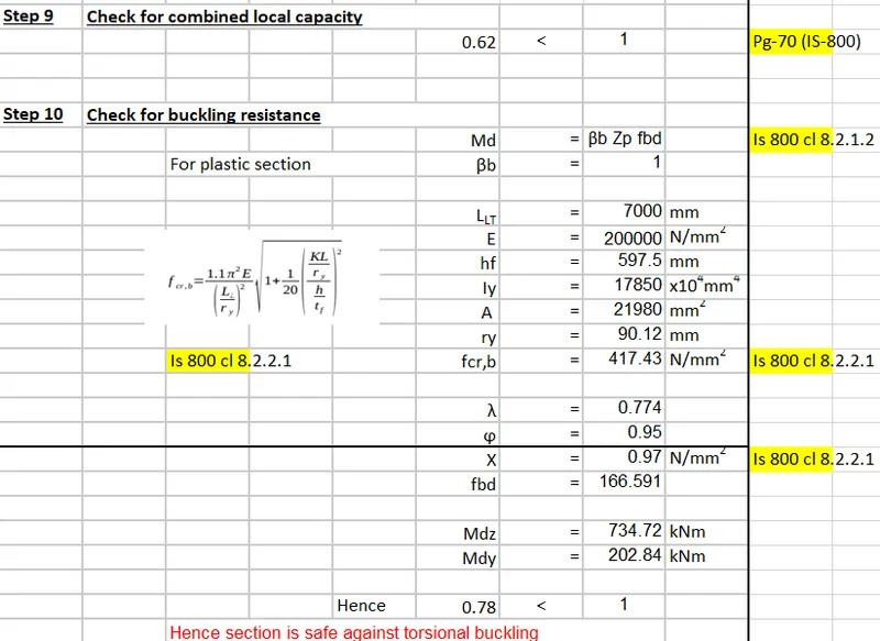
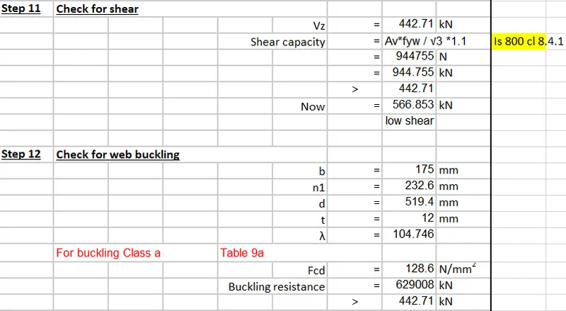
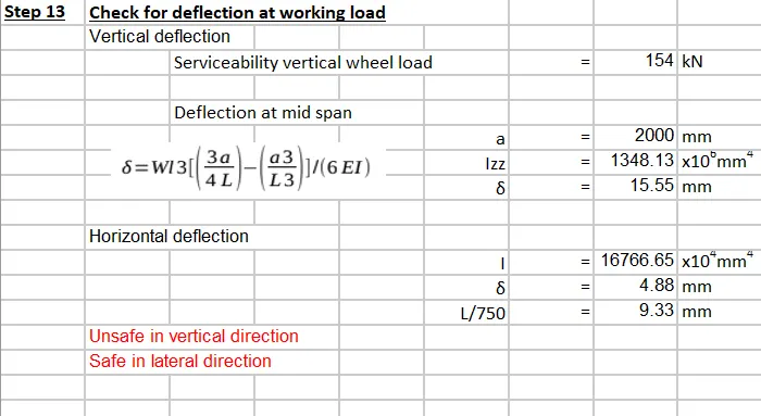
Q.2. Design a simply supported gantry girder to carry electric overhead travelling crane
Given:
Span of gantry girder = 7 m
Span of crane girder = 9 m
Crane capacity = 250 kN
Self-weight of trolley, hook, electric motor etc. = 40 kN
Self-weight of crane girder excluding trolley = 100 kN
Minimum hook approach = 1.0 m
Distance between wheels = 3 m
Self-weight of rails = 0.2 kN/m
Ans=
Conclusion:-
All the results has been displayed and EXCEL files regarding steel column design, wind load calculation, steel rafter design, base plate design, pedestral design, purlin design and simply supported gantry girder is attached in this project. Moreover, I have attached main staad model and analysis file along with staad foundation design file.