Project 2
Question:
- Emulate Torque-Speed characteristics of the designed IPM motor in Ansys Maxwell.
- Change the types of magnets and stator/rotor. Run simulations again and prepare a detailed report of the results.
Objective:
The objective of this simulation is tu observe the effects which different magnects type could have on the Torgue speed characteristics of an IMP motor.
-Since the Transient setup can not be done on this software version we are going to observe the influence the different magnectic types could have on the Mag_B (flux density) and Mag_H(flux) lines of a motor and also observe the torgue troduce when stator is excited.
Mag_B(flux Density) With Magnect type (N36Z_20):
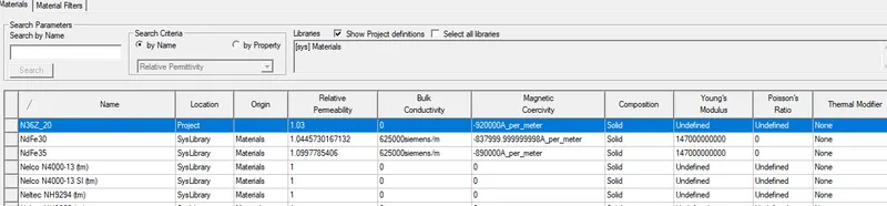
For this simulation the Permanent magnects used is the N36Z_20 type with its characteristic as shown below.
Before starting with the simulation we have to build an IPM motor on Maxwell. So a new project is created for IPM motor.
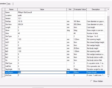
-The data for the slotcore of the stator are entered shown below. This automaticaly builds the slots and stator.
-Next the IPM core or the rotor is build with following datas
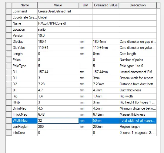
-By copying and pasting rotor then changing infocore value of rotor from 0 to 1 i created the rotor inner magnects and gave them a red colour.
-The lapcoil for the stator is created by enterying lapcoil values and choosing 1 for infocoil parameter.
-Coils are then duplicated and rotated around the Axsis to fill in the slots with coil.
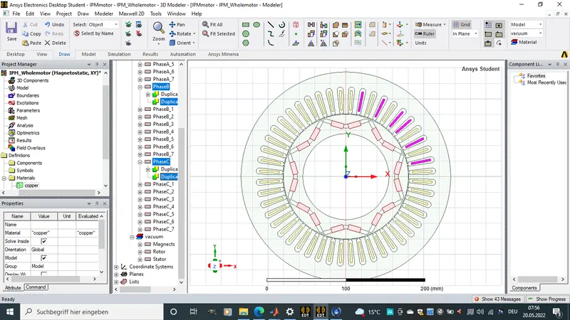
-The IPM motor model is divided to 1/8 along the axsis.
-A line is created along the model.
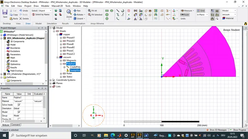
- Face orientation or direction of the permanent magnects is choosen by selecting face mode, then selecting the PM and choosing coordinate system from Modeler on the tool bar. in coordinate system, select creat and face_CS.
-Rotor material setting.
The rotor is set to steal with the name M19_29G. The Relative permeability is set to non linear.
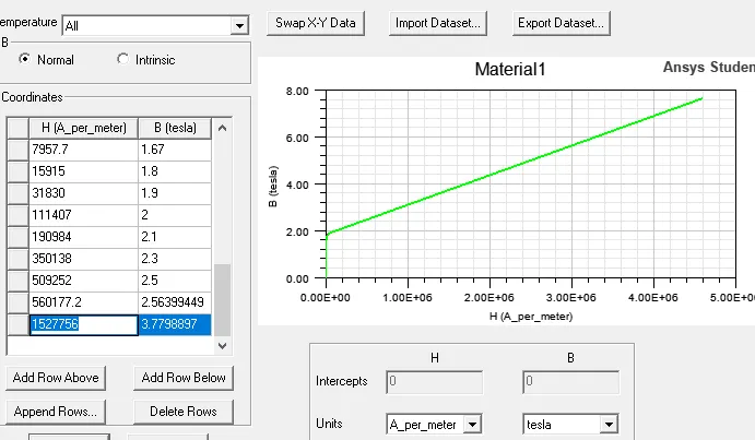
-Then a B-H curve for the rotor material isbuild by filling in the table values for the curev as below.
-This values help to calculate and estimate core losses. For material with above 2T of magnetic flux show how strong and robust the material is. The greater the B value the better the material.
-It is very important to get a good BH curve for stator and rotor when designing a motor.
-The stator is also made of the same material.
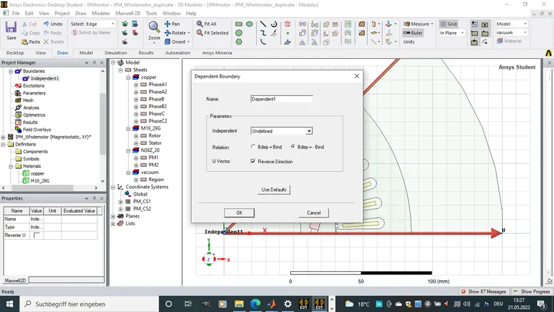
-Boundary selection of the IPM motor is made:
-Magnetostatic analysis:
-For this Analysis, Slover inside and Model are unchecked and taken out of the model.
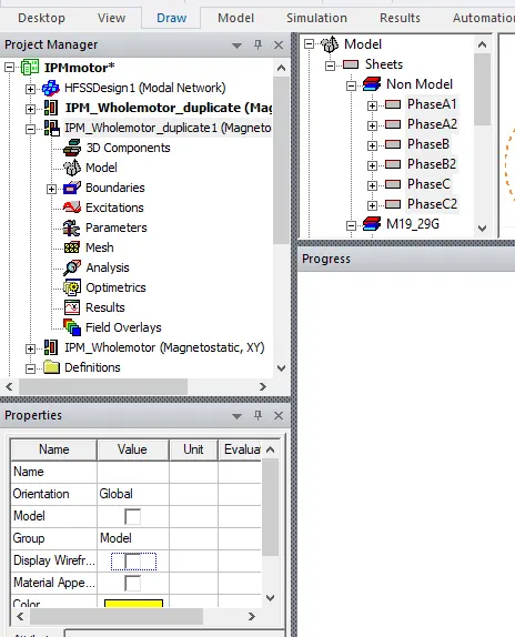
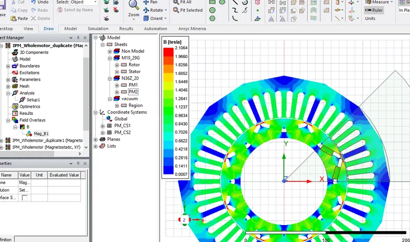
*Mag_B(Flux density) plot:
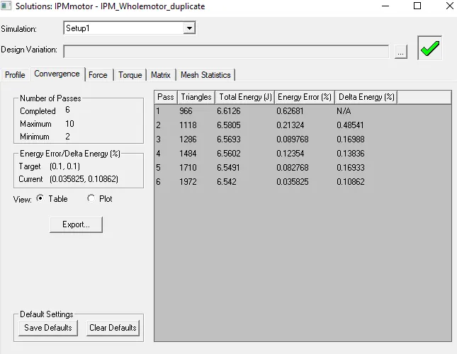
-Before plotting the magnetic flux density, solver type is set to Magnectostatic and torgue Analysis od the motor is carried out and shown below. Torgue value was very low since all stator windings were previously removed.
Mag_B (flux density)
Results:
-Regions with blue Mag_B colour show very week magnectic flux density while green region show average flux density and Red show strong magnectic flux density.
-From The first plot we notice a saturation at the rotor bridges. This is due to the short circuit between stator and rotor. This is also cause by the face direction of the permanent magnects.
Mag_H(flux) lines With Magnect type (N36Z_20):
To observe the mag_H plot of the motor we build a 3 point arc across the rotor stator boundry then plot a mag_H vector plot.
-Then the model is Duplicated for further analysis. Copper pahse coils are been braught back and and exited by assigning curent to the copper phases.The Copper phases are then grouped into group A , B and C as shown below.
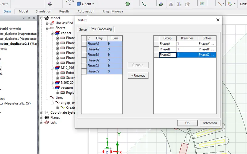
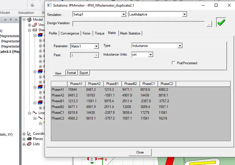
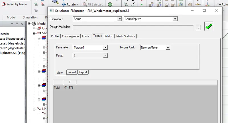
-Now the coils are now windings since they have some exitation. The model is once more Analysed. The following results for current and Torgue.
-We notice now that there is a greater torgue value than when there was no exsitation in the coil.
-Mag flux of the motor was ploted and shown below. we notice how the flux dose not go over the zero potential. they turn to converge along the zero potential line and flow back towards the motor center.
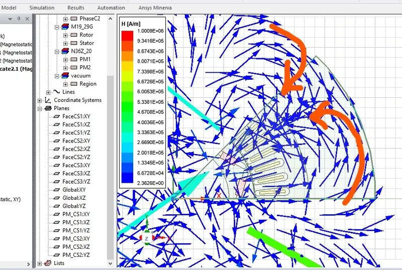
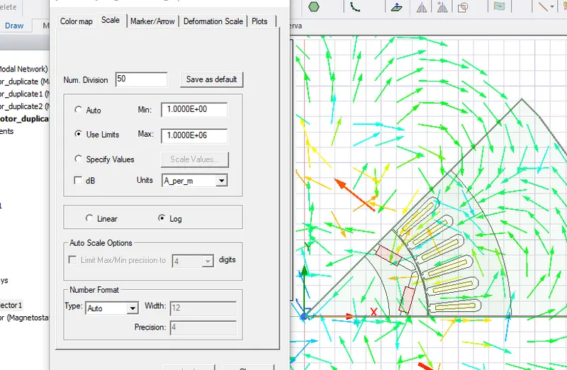
-the reason why they are all blue is due to the varition range. so when we change the variation rage we observe the following.
-We can also prove that our motor is working by observing the dirrection of the flux lines which converges at the Zero_potential boundries and move torwards the motor canter and torwards the center diverge .
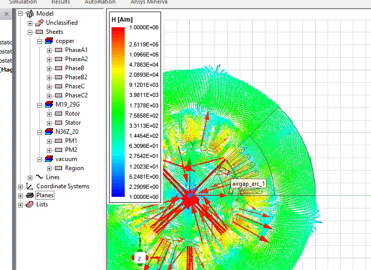
* The Torgue plot could not be ploted because the student vertion dose not suport the Transient Setup
Somne of the differences observed was as follwos.
-The Torgue was at a value of 0.001Nm when thers was no excitation or no current flow in the windings of the stator.
-The Torgue attained a significant value of 41.7 Nm After or with current flow in the stator windings was asigned.
Mag_B (Flux Density) and Mag_H (flux) with PM N45Z type:
The Permanent magnects type where changed to N45Z with the below characteristics
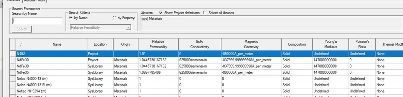
-The mag_B plot was as below.
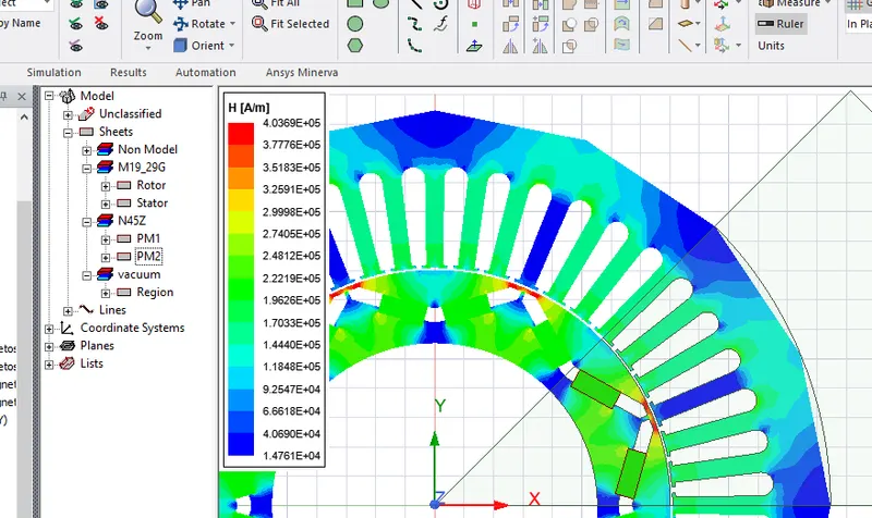
-The mag_H (flux) plot was as below.
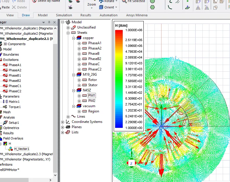
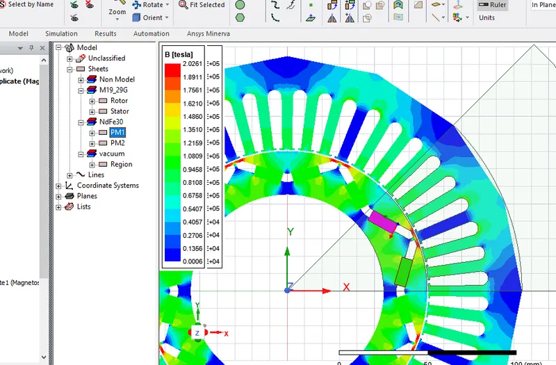
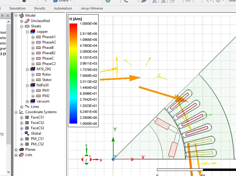
*The Mag_B (flux density) and Mag_H(flux) was also plotted for the below magnect type Ndfe30:
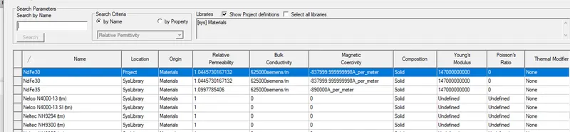
-The mag_B(Flux density) plot was as below.
-The mag_H(Flux) plot was as below.
Results and conclution.
-From all three Mag_B flux density lines we notice they are much very similar dispite the different magnects types used,this is because there is no exsitation in the rotor to creat a variation or to influence the magnects flux density lines.
-For the Mag_H flux lines plot of the three differnet magnects used we observe some differences.
-The first two magnects (N36Z_20 and N45Z) had very similar results this is because there magnects type where very similar in properties and had ver good Relative permeability and Magnectic Coercivity.
-The last magnect type Ndfe30 on the oder hand has very bad or very week flux lines. Dispite the Relative permeability and Magnectic Coercivity of the magnects it as a relative not so good Bulk conductivity value which the impurity of the magnect type been used.