Project 2
Aim : To calculate the water current forces, centrifugal forces, wave forces, snow load, temperature load, barge impact load on the bridge.
Given data :
- Dead weight tonnage of panamax vessel is 25000 DWT.
- Span of bridge is 40 m
- Width of bridge is 10.5 m
- The pier of size is 1.2 x 1.2 m
- The girder size is 1.6 x 2 m
- Thickness of flange and web is 0.3m
- Cr = 0.4, Cva = 3
- Storm elevation is 8.5 m
Calculation :
- Water current forces
High flood level – 4 m
Mean velocity of river – 2.5 m/s
Maximum velocity, V = √2 x Vmean
= √2 x 2.5
V = 3.53
Water current, P = 52 x K x V2
= 52 x 1.5 x 3.532
P = 971.95 KN/m2
- Centrifugal forces
Design speed of vehicle = 50 km/hour
Radius of curvature = 2 m
Live load , W = 70 KN
Centrifugal force = ( W x V2 ) / (127 x R )
= ( 70 x 502 ) / ( 127 x 2 )
Centrifugal force = 729.16 KN
- Wave force
Δ Zh = ηmax – centroid of girder
= 3 – ( 1.6 / 2 )
Δ Zh = 2.2 m.
Δ Zv = ηmax - elevation of bottom deck
= 3 – 1.5
Δ Zv = 1.5 m
Number of girder , N = 4
Vertical load, Fv = r x Δ Zv x Av
= 5 x 1.5 x ( 105 x ( 1.6/2))
Fv = 63 KN
Horizontal load, Fh = r x Δ Zh x Ah
= 5 x 2.2 x ( 3 x 40))
Fh = 1320 KN
Max vertical load , Fv max = Cva x Fv
= 3 x 63
Fv max = 189 KN
Max horizontal load , Fh max =[ 1 + Cr ( N – 1 ) ] Cva x Fh
= [ 1 + 0.4 ( 4 – 1 )] 3 x 1320
Fh max = 8712 KN
- Snow load
The snow is damped new snow = 2 KN/m3
The deck of bridge is flat with β < 30°
The depth of accumulation of snow is 1250 mm
Snow load, S° = density x area
= 2 x 1.2 x 40
Snow load, S° = 96 KN/m
Shape coefficient from I.S 875 part 4
For β < 30° , µ = 0.8
Design snow load, S = µ x S°
= 0.8 x 96
Design snow load, S = 76.8 KN/m
- Temperature load
Max temperature in location as per IRC 6 at the location is 48.4°
Min temperature in location as per IRC 6 at the location is -2.2°
Effective temperature difference = ( 48.4 – ( -2.2) ) / 2 + 10 = 35.3°
Stress due to temperature = ɑ x Δ T x E
= 11.27 x 10^-6 x 35.3 x 5000 ( 40 )0.5
Stress due to temperature = 12.58 kn/m^2
Max permissible stress = ( 2/3 ) x 0.7 x (40)0.5 = 2.92 kn/m2
Positive temperature difference
Temperature at top = 48.4°
Temperature at bottom = (2.1/17.8) x 48.4 = 5.71°
- Barge impact load
Hydrodynamic coefficient 1.25
KE = 500 x CH x W x V2
= 500 x 1.25 x 25000 x 13.852
KE = 299.7 x 10⁷
ɑβ = 3100 x [ 1 + ( 1.3 x 10-7 x 299.7 x 107]0.5 -1)
ɑβ = 58167.95
Pβ = 6 x 10⁶ + ( 1600 + 58167.95)
Pβ = 3.58 x 10¹¹ N
Aim : To prepare the model in a STAAD Pro and perform the analysis and justify with the results.
Theory : The general steps to be create a STAAD Pro model is given below,
Step 1 : Create the nodes by using the nodes cursor.
Step 2 : Joining the nodes by using the respective beam plate cursor.
Step 3 : Supports given to the nodes whether its pinned or fixed or any other custom supports
Step 4 : specifications given to the respective beams plates
Step 5 : Assign the dead load as per calculation
Step 6 : Save the model and perform the analysis
Step 7 : The results are obtained and discuss with the results
Step 8: Take the print out of report of necessary results.
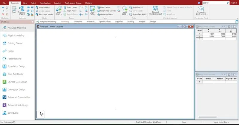
Creating the nodes by using node cursor.
Open the STAAD Pro window > Select > Node cursor > enter the value with respect to X Y Z axis > click enter
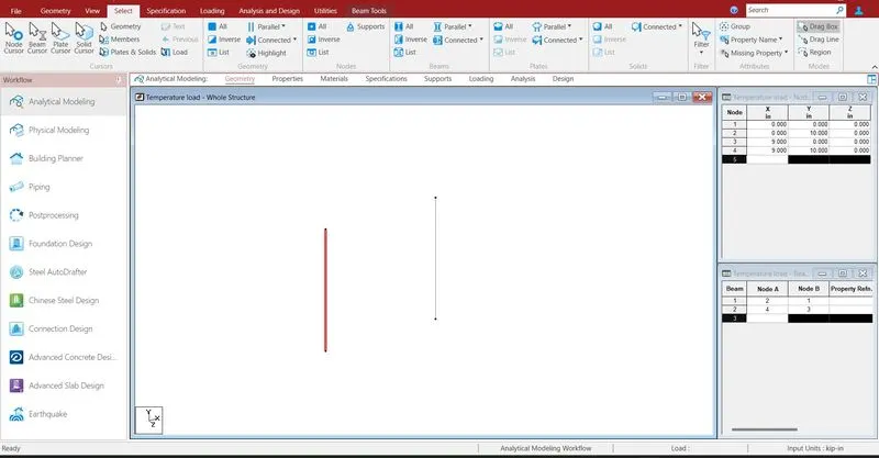
Join the nodes by using beam cursor.
Select > beam cursor > join by dragging the mouse or enter the node numbers > click enter
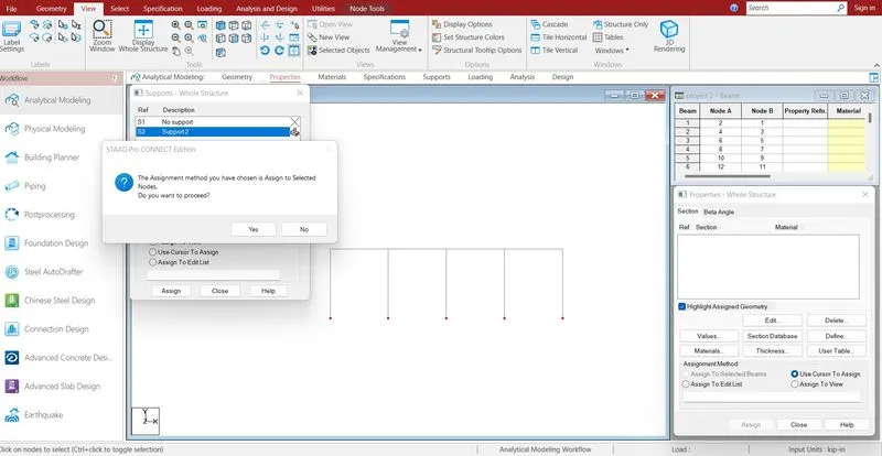
Supports are given to the respective nodes.
Specifications > Supports > select the supports > click enter
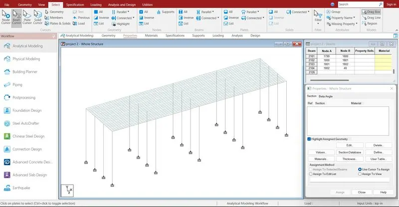
deck slab has been created by using mesh like structures.
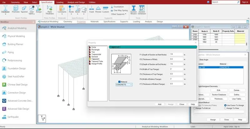
Assigning the properties to the beam .
Specification > Prismatic > Rectangle > enter dimensions > select the beam > assign the properties to selected beams.
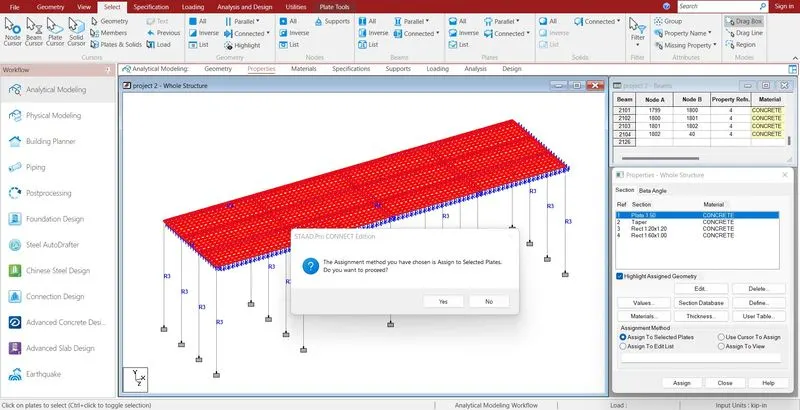
Specification > Plate thickness > enter the dimension > select plates > ok
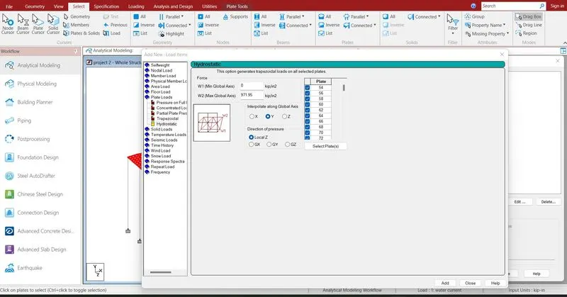
Defining the load cases .
Loading > Load case detail > water current load > Add
Add > plate load load > hydrostatic load > enter the value > ok
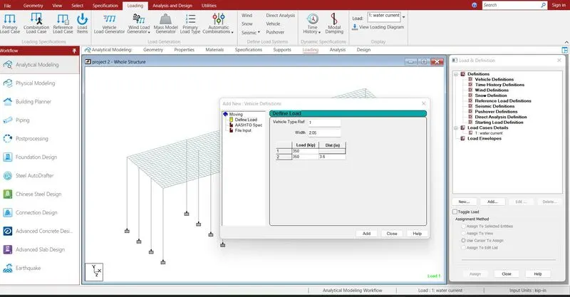
define > vehicular load > define > add
load case detail > load generation > add
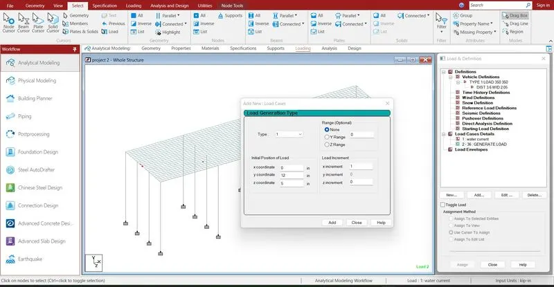
add > enter the ranges > ok
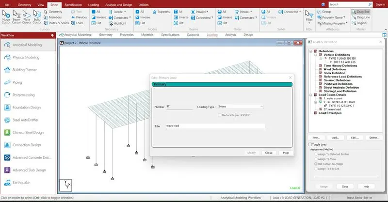
load case detail > wave load > add
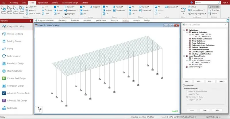
add > plate load > hydrostatic pressure > add
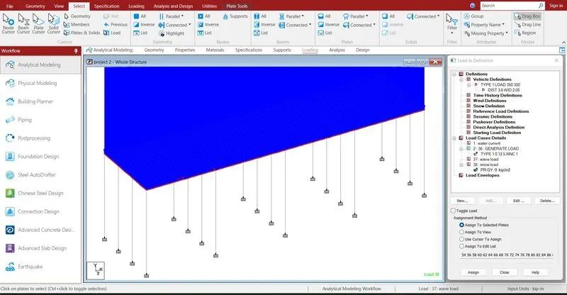
load case detail > add > snow load > plate load > ok
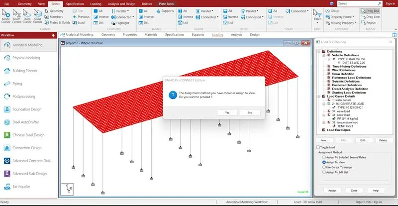
load case detail > temperature load > click add > assigned to view
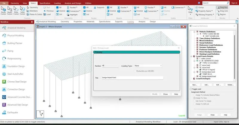
load case detail > barge impact load > add
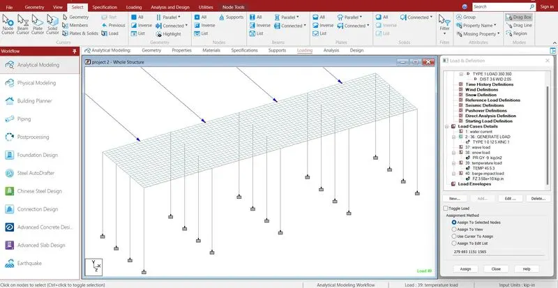
Add > point load > enter the value > ok
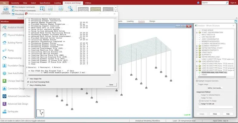
Run analysis > go to post processing mode > Results
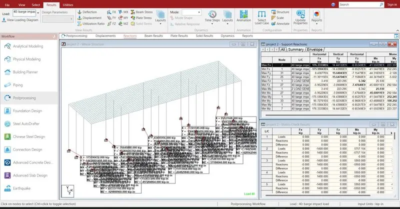
The reactions are generated at the end of the nodes .the reaction value is 176.5 KN
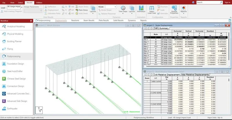
- The maximum deflection in X direction is 30.71 mm barge impact load
- The minimum deflection in X direction is -30.97 mm barge impact load
- The maximum deflection in Y direction is 41.39 mm barge impact load
- The minimum deflection in Y direction is -41.37 mm barge impact load
- The maximum deflection in Z direction is 2.142 mm barge impact load
- The minimum deflection in Z direction is -0.142 mm due to load case 5
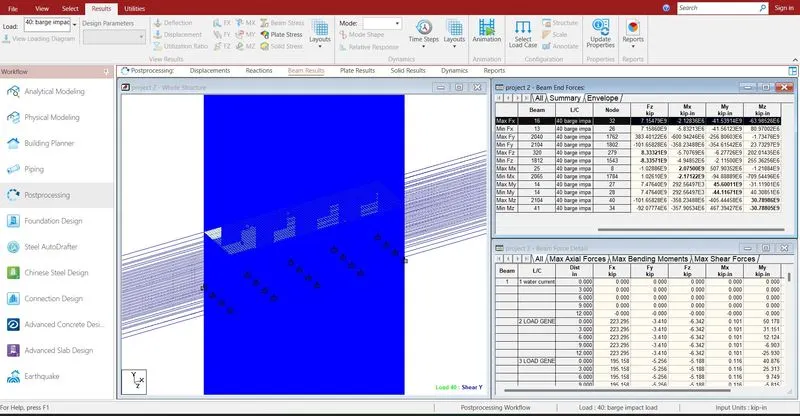
- The maximum shear force in X direction is 15.64 KN barge impact load
- The minimum shear force in X direction is -15.64 KN barge impact load
- The maximum shear force in Y direction is 2.101 KN barge impact load
- The minimum shear force in Y direction is -14.11 KN barge impact load
- The maximum shear force in Z direction is 8.33 KN barge impact load
- The minimum shear force in Z direction is -8.33 KN barge impact load
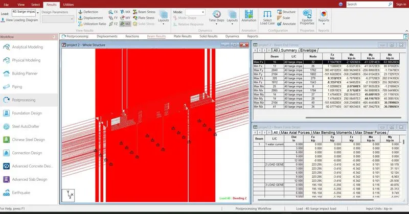
- The maximum bending moment in X direction is 2.07 KN-m barge impact load
- The minimum bending moment in X direction is -2.17 KN-m barge impact load
- The maximum bending moment in Y direction is 45.6 KN-m barge impact load
- The minimum bending moment in Y direction is -44.11 KN-m barge impact load
- The maximum bending moment in Z direction is 30.78 KN-m barge impact load
- The minimum bending moment in Z direction is -30.78 KN-m barge impact load
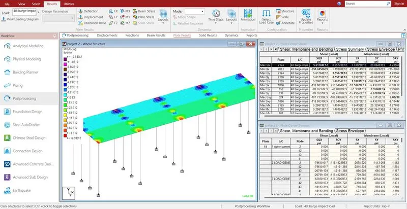
- The maximum shear stress in X direction is 1.93 KN/m2
- The minimum shear stress in X direction is -15.26 KN/m2
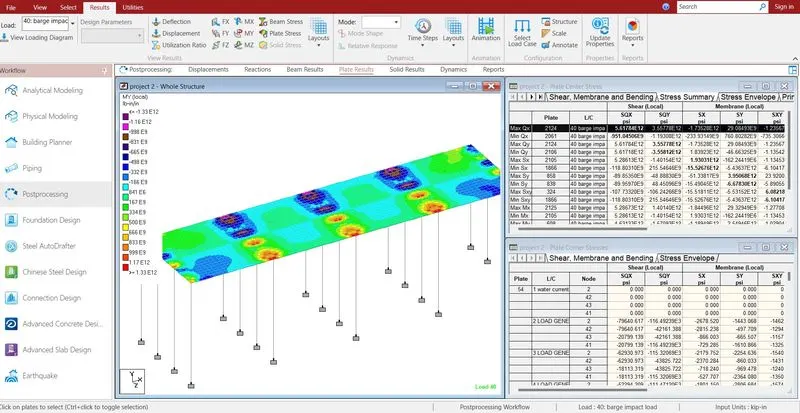
- The maximum shear stress in X direction is 3.9 KN/m2
- The minimum shear stress in X direction is -6.67 KN/m2
- Reports are taken printout which ever is necessary by using report
- In the report option we obtain the results of section forces, displacement, reactions, plate
- The exact report is to be taken further move to design