Project 2
Objective: The primary objective of this project is to develop a comprehensive forward energy-based fuel consumption model for a P1 hybrid electric vehicle, specifically utilizing the Honda Insight's motor and battery data and various drive cycles.
This vehicle model aims to:
- Quantify Fuel Efficiency Improvements: Assess and quantify the enhancements in fuel economy (kmpl) of the hybrid vehicle compared to a conventional vehicle model under various driving conditions, particularly the urban (UDDS) and highway (HWFET) cycles.
- Analyze Vehicle Dynamics: Investigate and analyze critical operating parameters of the hybrid vehicle, including engine and motor speeds, torque outputs, transmission dynamics, pedal positions, battery state of charge (SoC), and overall energy consumption.
- Visualize Performance Metrics: Generate detailed visualizations of the hybrid vehicle's performance, including time traces and subplots of key metrics such as torque, power, fuel consumption, and operating points on fuel and power maps, to enhance understanding of the hybrid system's functionality.
Firstly we initialize and load all the required vehicle model parameters via MATLAB script.
We load the data files in command window as follows:
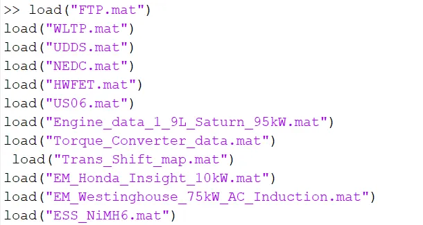
Now, the variables present in the data files are visible in the workspace.
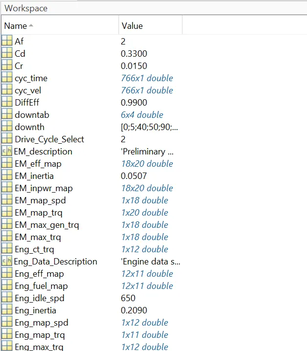
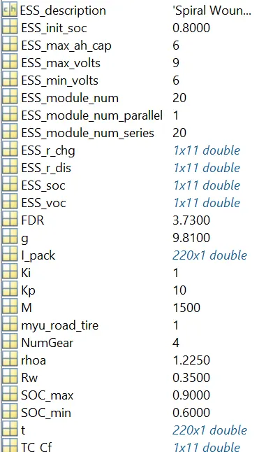
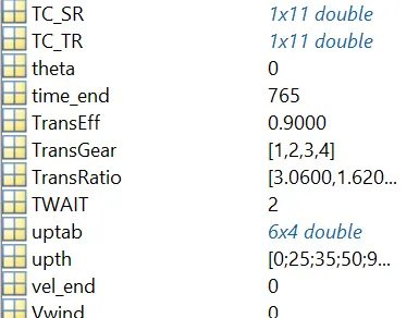
MATLAB SRIPT/CODE for initialization of variables:
%% Vehicle Parameters
M = 1500; % Vehicle weight [kg]
Cr = 0.015; % Rolling resistance coefficient
Rw = 0.35; % Rolling radius [m]
Cd = 0.33; % Drag coefficient
Af = 2; % Frontal area [m2]
rhoa = 1.225; % Air density [kg/m3]
Vwind = 0; % Wind velocity [kmph]
g = 9.81; % Gravitational acceleration [m/s2]
theta = 0; % Slope [deg]
myu_road_tire = 1; % Coefficient of friction between tire - road interface
%% Powertrain Parameters
FDR = 3.73; % Final Drive Ratio / Diff Ratio
DiffEff = 0.99; % Differential efficiency (assumed independent of operating conditions)
NumGear = 4; % Number of gears in transmission
TransGear = [1:NumGear]; % Transmission Gears
TransRatio = [3.06, 1.62, 1, 0.7]; % Corresponding Transmission ratios
TransEff = 0.90; % Transmission efficiency (assumed independent of operating conditions)
TC_SR = [0, .5, .6, .7, .8, .87, .92, .94, .96, .97, 1]; % Torque Converter Speed Ratio (Matlab default) -> TurbSpd/PumpSpd
TC_TR = [2.232, 1.5462, 1.4058, 1.2746, 1.1528, 1.0732, 1.0192, 1, 1, 1, 1]; % Torque Converter Torque Ratio (Matlab default) -> TurbTrq/PumpTrq
TC_Cf = 1e-4 * [.72558, .66322, .63463, .59042, .51331, .4144, .29287, .22444, .12186, .04386, 0]; % Torque Converter Capacity Factor (Matlab default) -> PumpTrq/PumpSpd^2 [Nm/rpm^2]
load ('C:\Users\SURYA\OneDrive\Desktop\MATLAB TASK FILES\Project 2/Engine_data_1_9L_Saturn_95kW')
load ('C:\Users\SURYA\OneDrive\Desktop\MATLAB TASK FILES\Project 2/Trans_Shift_map')
load ('C:\Users\SURYA\OneDrive\Desktop\MATLAB TASK FILES\Project 2/EM_Honda_Insight_10kW')
load ('C:\Users\SURYA\OneDrive\Desktop\MATLAB TASK FILES\Project 2/ESS_NiMH6')
ESS_init_soc = 0.8;
SOC_max = 0.9;
SOC_min = 0.6;
%% Driver Parameters
Kp = 10; % P gain for driver PI model
Ki = 1; % I gain for driver PI model
Drive_Cycle_Select = 2; % Drive cycle selection
% Drive cycle values in m/s
if Drive_Cycle_Select == 1
load ('C:\Users\SURYA\OneDrive\Desktop\MATLAB TASK FILES\Project 2/UDDS');
elseif Drive_Cycle_Select == 2
load ('C:\Users\ SURYA \OneDrive\Desktop\MATLAB TASK FILES\Project 2/HWFET');
elseif Drive_Cycle_Select == 3
load ('C:\Users\ SURYA \OneDrive\Desktop\MATLAB TASK FILES\Project 2/FTP');
elseif Drive_Cycle_Select == 4
load ('C:\Users\ SURYA \OneDrive\Desktop\MATLAB TASK FILES\Project 2/US06');
elseif Drive_Cycle_Select == 5
load ('C:\Users\ SURYA \OneDrive\Desktop\MATLAB TASK FILES\Project 2/NEDC');
elseif Drive_Cycle_Select == 6
load ('C:\Users\ SURYA \OneDrive\Desktop\MATLAB TASK FILES\Project 2/WLTP');
end
time_end = cyc_time(end);
vel_end = cyc_vel(end);
Summary:
This code sets up the necessary parameters for a hybrid vehicle model, loads essential data, and prepares for simulations by selecting a drive cycle and initializing the energy storage system. Each section is crucial for modeling the vehicle's dynamics and energy consumption effectively.
Parallel (P1) Hybrid Vehicle Model: A Brief Overview
Construction
A Parallel P1 Hybrid Vehicle is a type of hybrid electric vehicle where an internal combustion engine (ICE) and an electric motor (EM) are connected to the same drivetrain. This configuration allows for both electric and gasoline power to be used independently or in combination.
Working
In a Parallel P1 Hybrid Vehicle:
- Electric-Only Mode: The electric motor drives the wheels, providing a silent and emission-free driving experience.
- Gasoline-Only Mode: The internal combustion engine drives the wheels, similar to a traditional gasoline-powered vehicle.
- Hybrid Mode: Both the electric motor and internal combustion engine work together to provide power to the wheels. This can improve fuel efficiency and performance.
Components
Key components of a Parallel P1 Hybrid Vehicle include:
- Internal Combustion Engine (ICE): Provides mechanical power to the drivetrain.
- Electric Motor (EM): Provides electric power to the drivetrain.
- Battery Pack: Stores electrical energy for the electric motor.
- Power Electronics: Controls the flow of electricity between the battery pack and the electric motor.
- Transmission: Transfers power from the ICE and/or EM to the wheels.
- Generator: Can convert mechanical energy from the ICE into electrical energy to charge the battery.
- Controller: Manages the overall operation of the hybrid system, including deciding when to use the ICE, EM, or both.
Advantages
· Flexibility: Can operate in electric-only, gasoline-only, or hybrid modes.
- Improved Fuel Efficiency: Can reduce fuel consumption compared to traditional gasoline-powered vehicles.
- Reduced Emissions: Can lower emissions compared to traditional gasoline-powered vehicles.
- Instant Torque: The electric motor provides instant torque, improving acceleration.
Disadvantages of Parallel P1 Hybrid Vehicles:
- Higher Cost: Typically more expensive to manufacture than traditional gasoline-powered vehicles.
- Increased Complexity: The hybrid system adds complexity and potential maintenance issues.
- Battery Weight and Size: Battery packs can add weight and reduce cargo space.
By combining the efficiency of electric power with the range and power of a traditional internal combustion engine(ICE), Parallel P1 Hybrid Vehicles offer a promising solution for reducing emissions(exhaust) and improving the economy of vehicle.
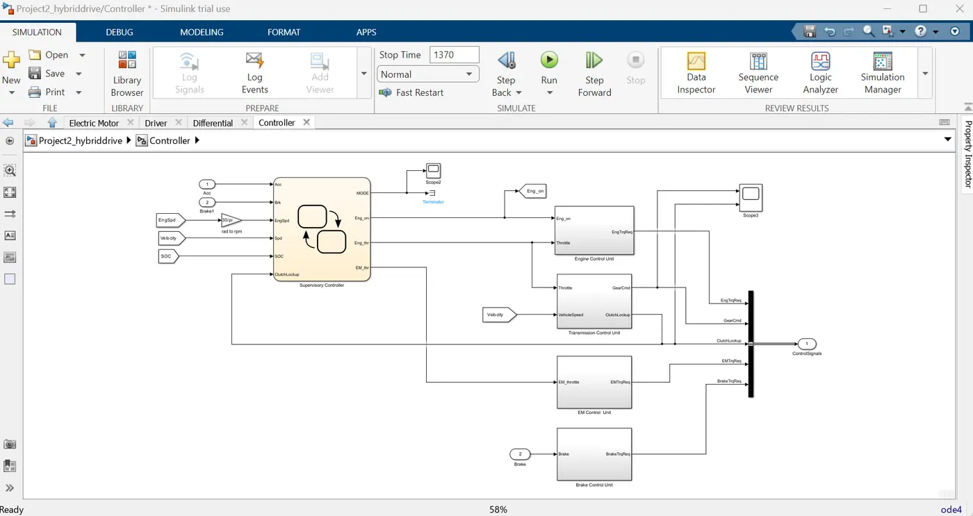
A parallel P1 hybrid vehicle requires a complex control system to efficiently manage the power flow between the internal combustion engine (ICE) and the electric motor (EM). This control system consists of several interconnected control units that work together to optimize performance/efficiency, fuel economy, and emissions.
Here are the key control units in a parallel P1 hybrid vehicle:
1. Powertrain Control Module (PCM)
- Core of the System: The PCM is the central control unit that coordinates the operation of all powertrain components.
- Key Functions:
- Power Management: Determines the optimal power split between the IC ENGINE( ICE) and EM based on factors like driver demand, battery state of charge (SOC), and vehicle speed.
- Gear Shift Control: Controls the transmission shifts to optimize efficiency and performance.
- Engine Start/Stop Control: Manages engine start/stop cycles to minimize fuel consumption and emissions.
- Regenerative Braking Control: Controls the braking system to recover energy and charge the battery.
- Fault Detection and Diagnosis: Monitors the system for faults and initiates appropriate actions.
2. Engine Control Unit (ECU)
- Dedicated to ICE: The ECU is responsible for controlling the operation of the internal combustion engine.
- Key Functions:
- Fuel Injection: Controls the amount of fuel injected into the engine cylinders.
- Ignition Timing: Controls the timing of the spark plugs to optimize combustion.
- Air-Fuel Ratio Control: Maintains the optimal air-fuel ratio for efficient combustion.
- Engine Speed and Torque Control: Regulates engine speed and torque output to meet the demands of the powertrain.
3. Motor Control Unit (MCU)
- Dedicated to EM: The MCU controls the operation of the electric motor.
- Key Functions:
- Motor Speed and Torque Control: Regulates the motor's speed and torque output to meet the powertrain's demands.
- Inverter Control: Controls the power electronics inverter to convert DC power from the battery to AC power for the motor.
- Regenerative Braking Control: Controls the motor's operation during braking to recover the lost (friction) energy and charges the battery.
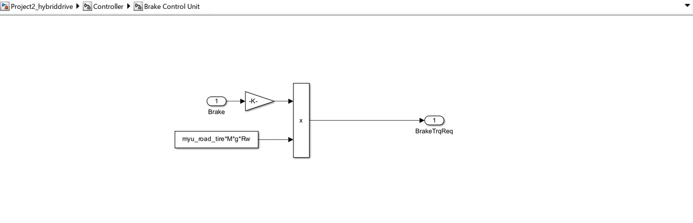
4. Brake Control Unit
- A brake control unit is a crucial component in a parallel P1 hybrid vehicle, responsible for managing the braking system to ensure safe and efficient operation. In hybrid vehicles, the BCU plays a more complex role than in traditional vehicles, as it must coordinate both mechanical and regenerative braking.
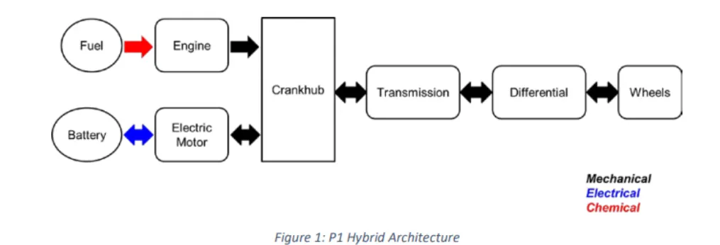
Now we will develop the Simulink model for the Parallel (P1) Hybrid Vehicle Model using following steps:
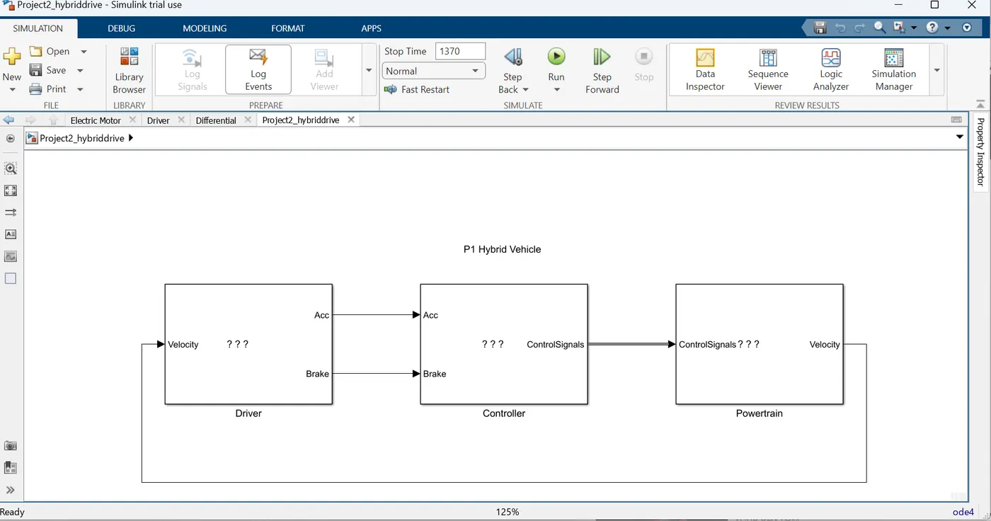
Now we will develop the Simulink model for the Parallel (P1) Hybrid Vehicle Model:
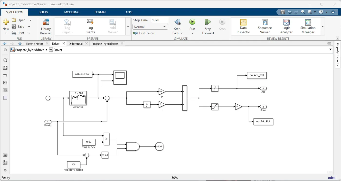
We add the driver, powertrain, controller blocks as ‘Subsystem’ block. Now we model the driver subsystem block using – ‘To workspace, Saturation, Constant, ‘1D Lookup table’, ‘Gain’ etc Simulink blocks.
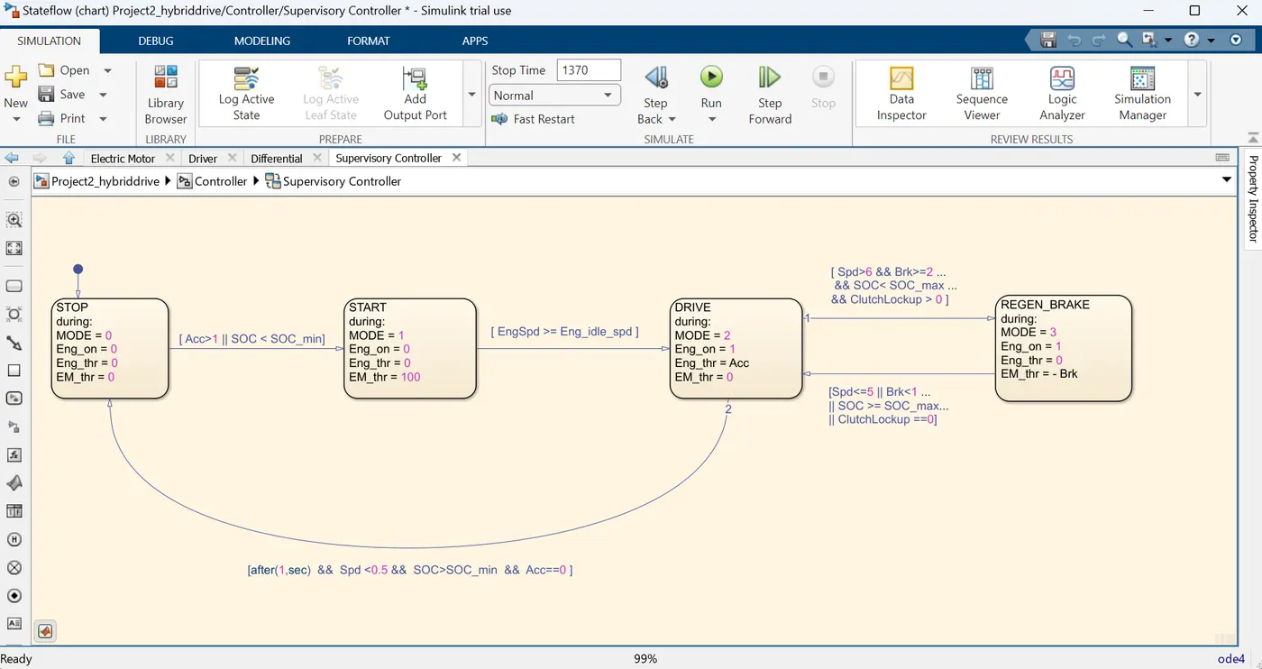
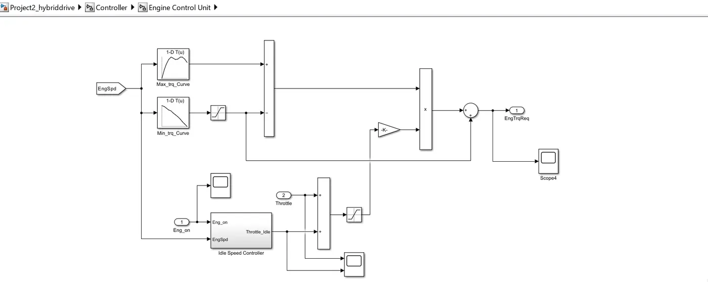
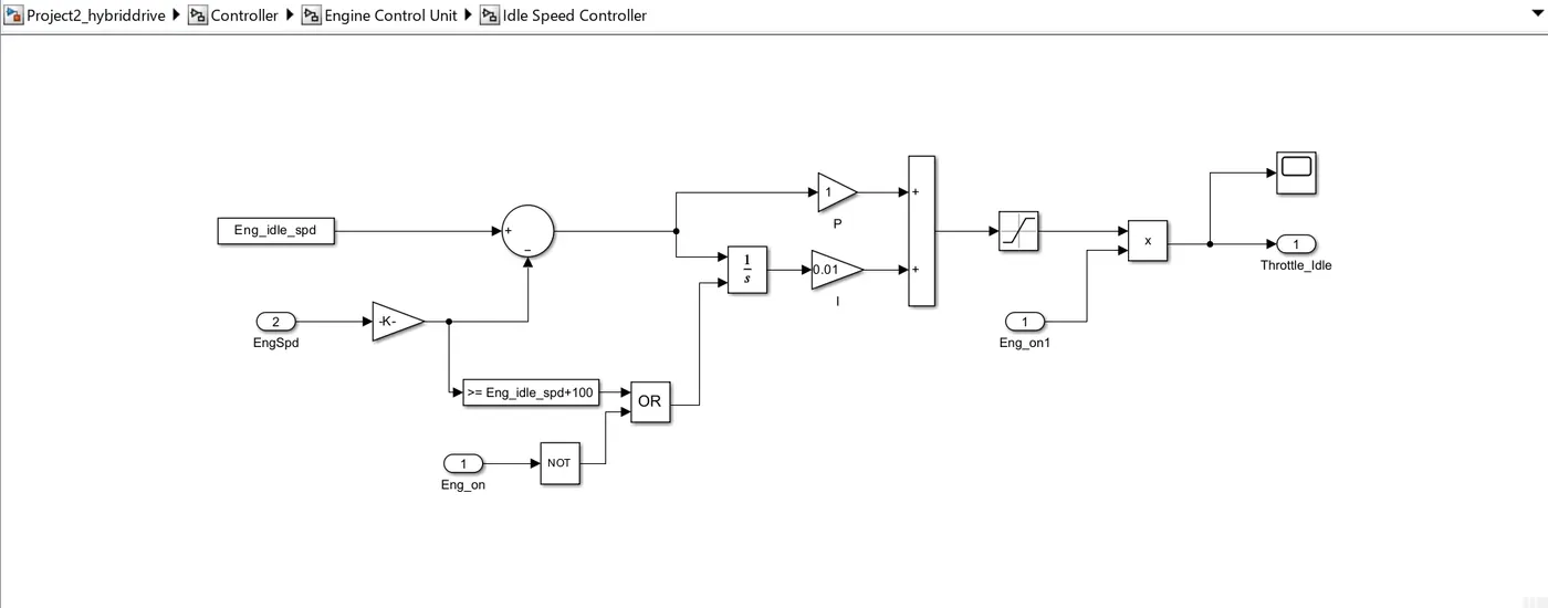
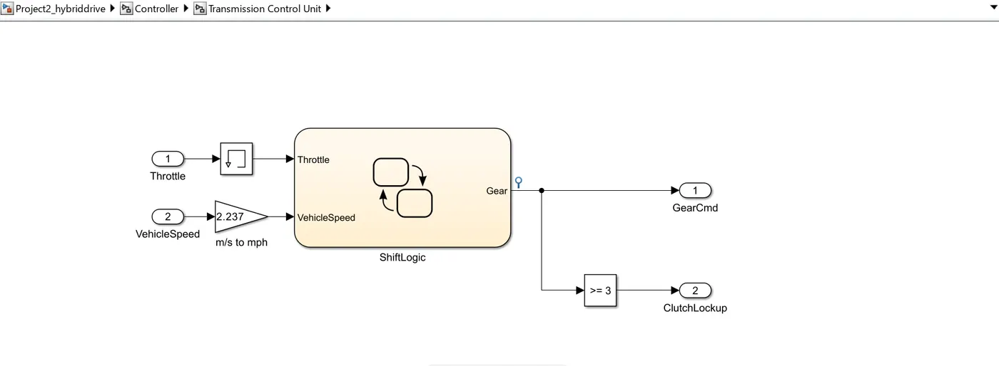
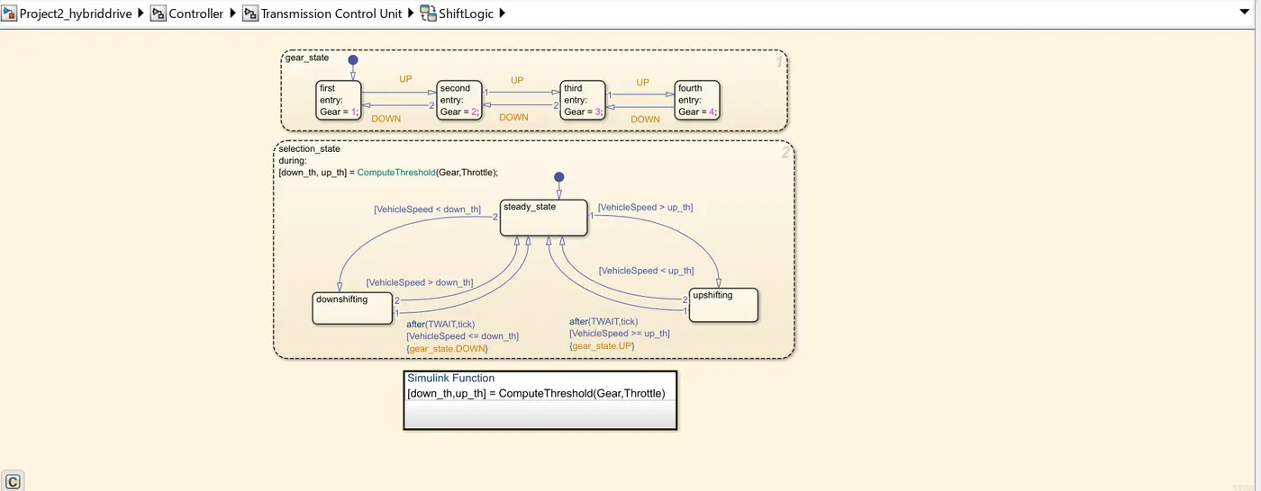
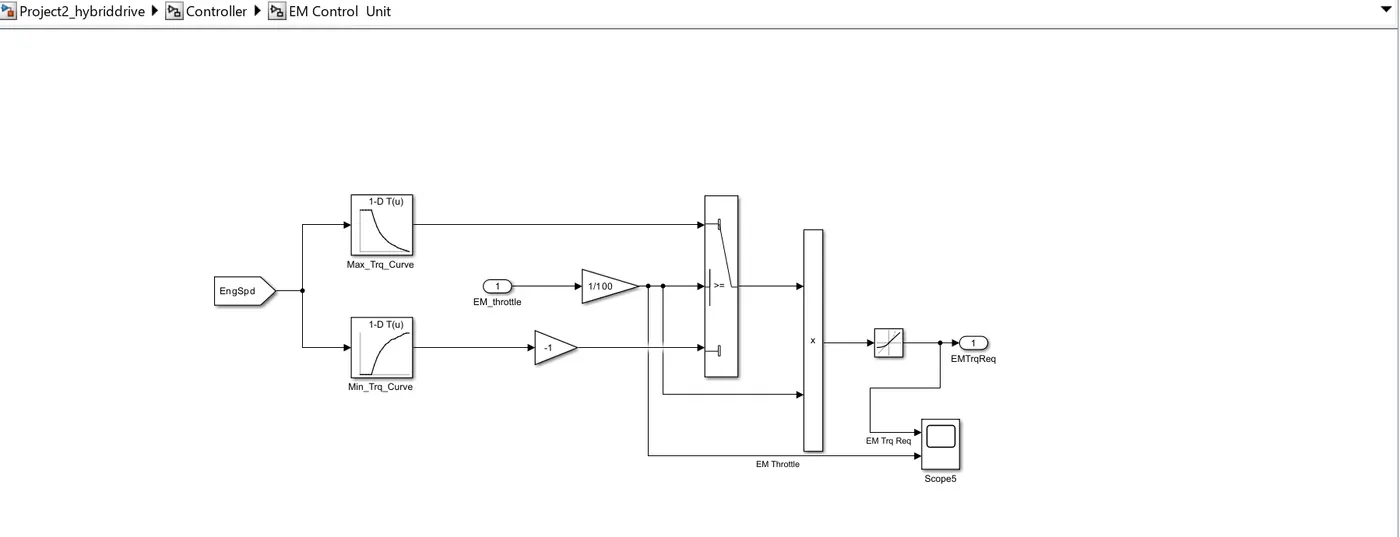
Now we model the ‘Controller’ subsystem block which further contains four control unit sub system blocks and a state flow block as follows:
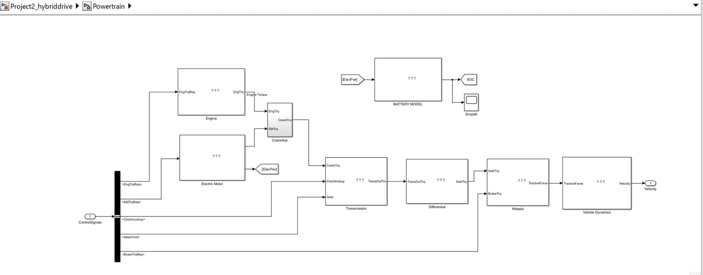
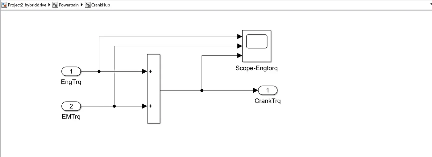
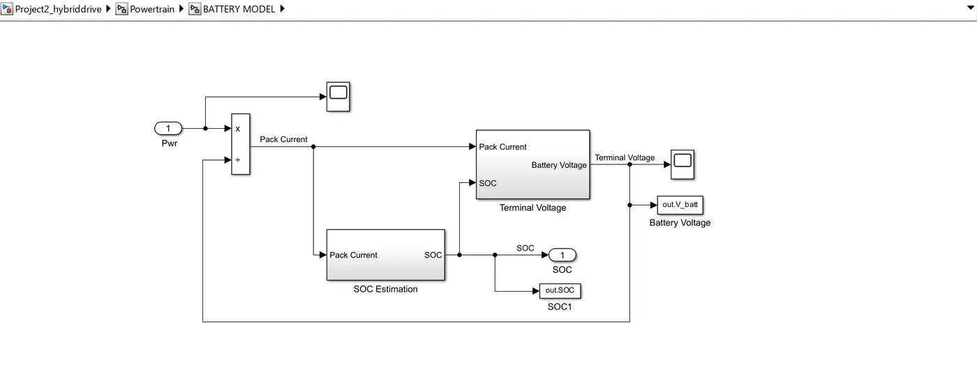
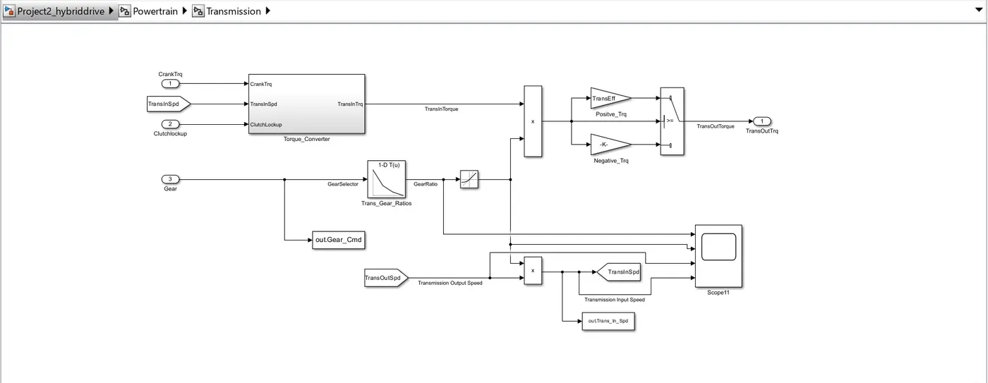
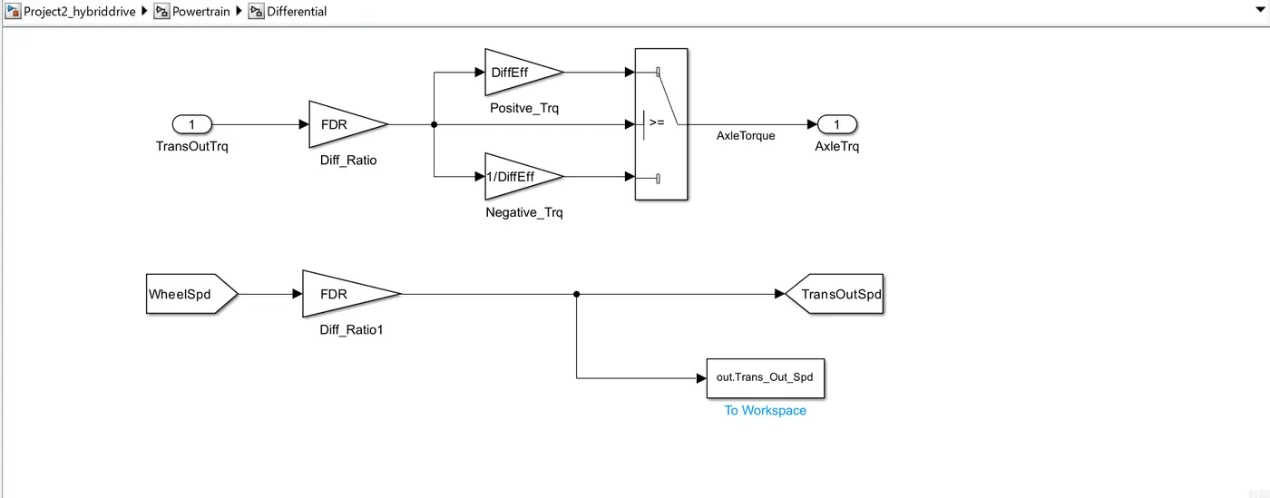
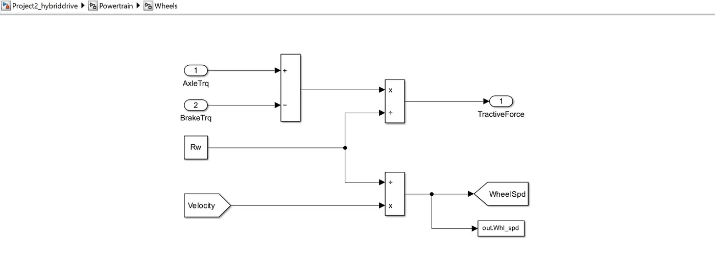
Now we model the ‘Powertrain’ subsystem block which further contain six subsystems –(CrankHub, Battery Model, Transmission, Vehicle dynamics, Wheels, Differential ) as follows:
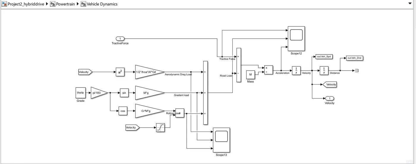
The block in Vehicle dynamics subsystem are added based on following working formula:


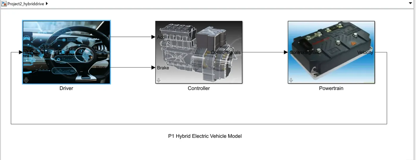
We can add mask to the Simulink blocks as images using 'edit mask' option.
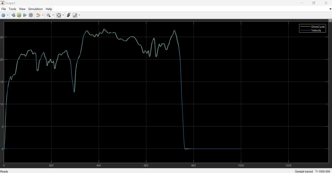
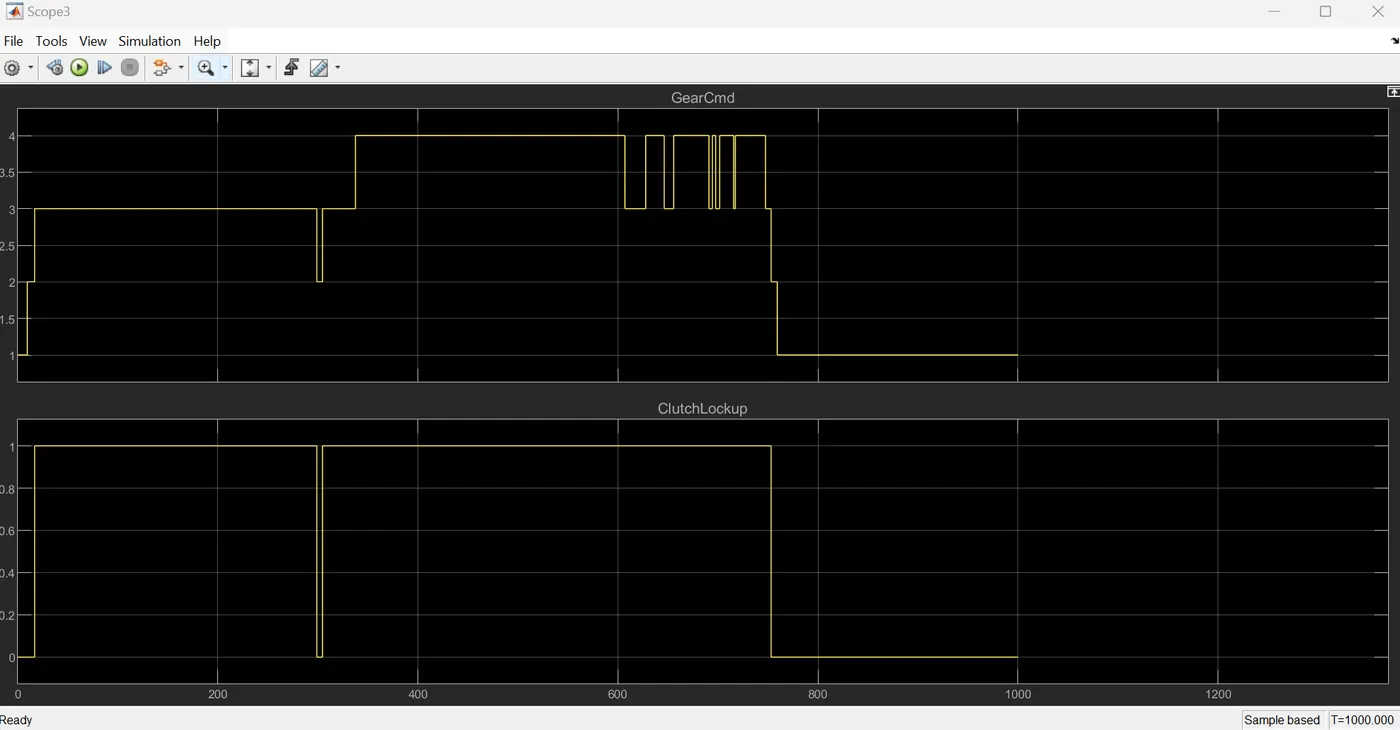
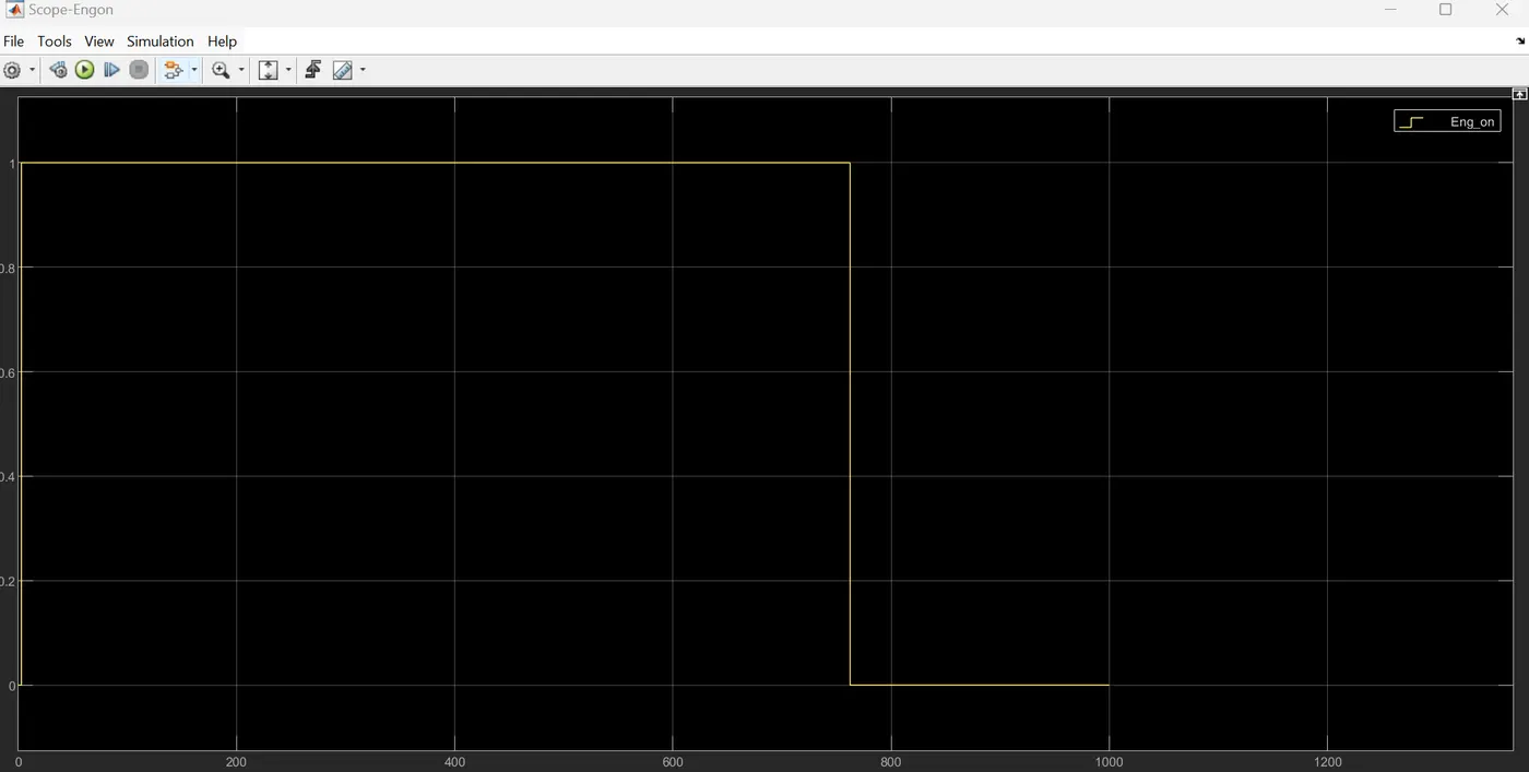
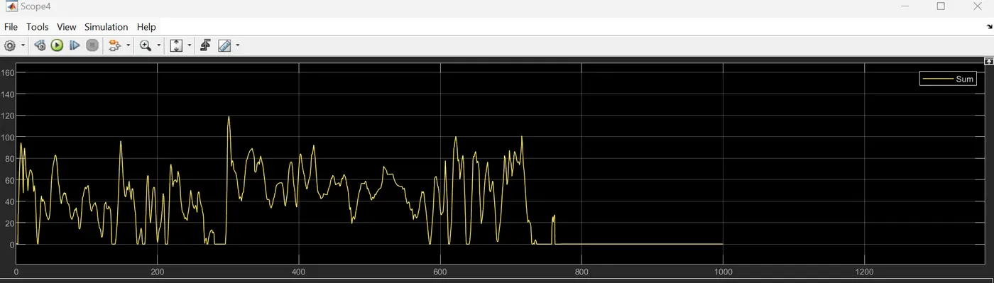
Now we run the simulation and observe the results of the SCOPE blocks for different subsystems as follows:
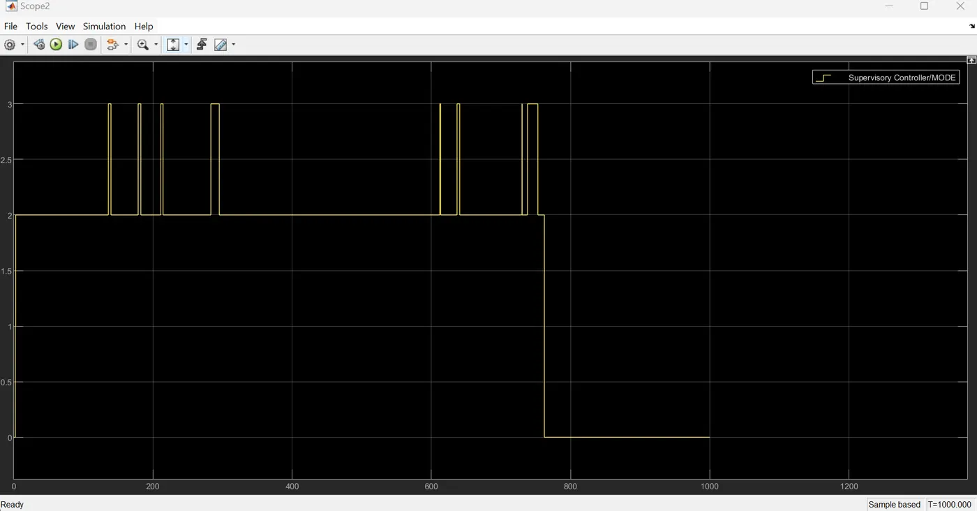
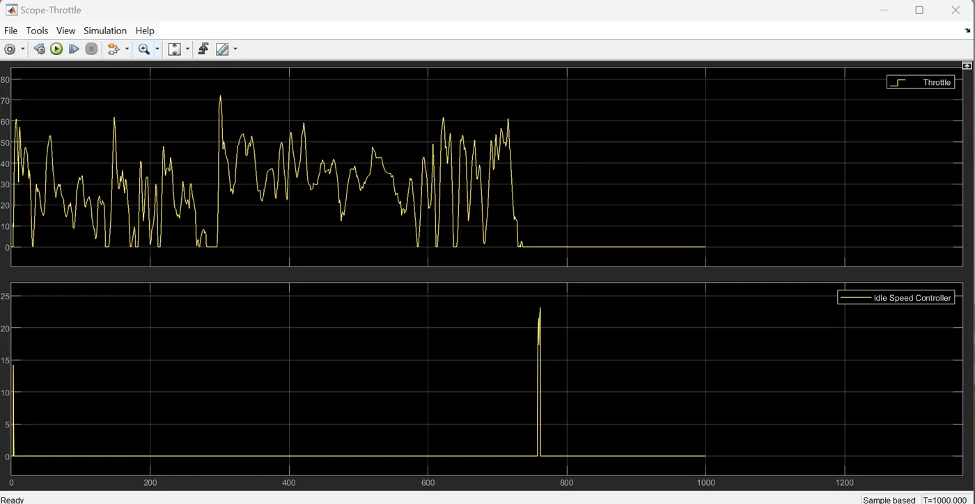
The two plots together represent the engine control strategy for a hybrid vehicle.
- The "Throttle" plot might represent the driver's input, while the "Idle Speed Controller" plot shows the system's response to maintain a desired idle speed.
- The "Idle Speed Controller" might be activated under certain conditions, such as when the vehicle is stopped or during transitions between different operating modes.
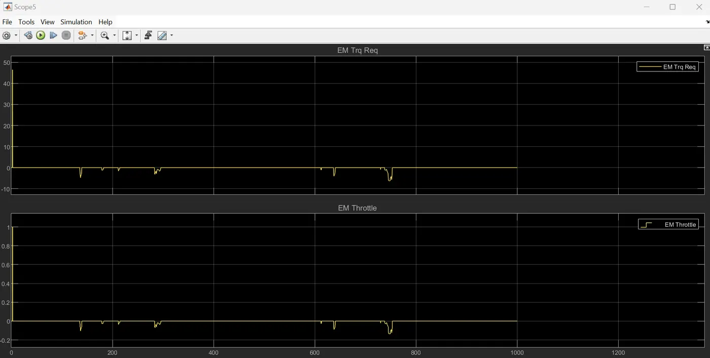
The plot shows how the EM throttle position changes over time. A higher value indicates a wider throttle opening, allowing more power to the EM(motor).
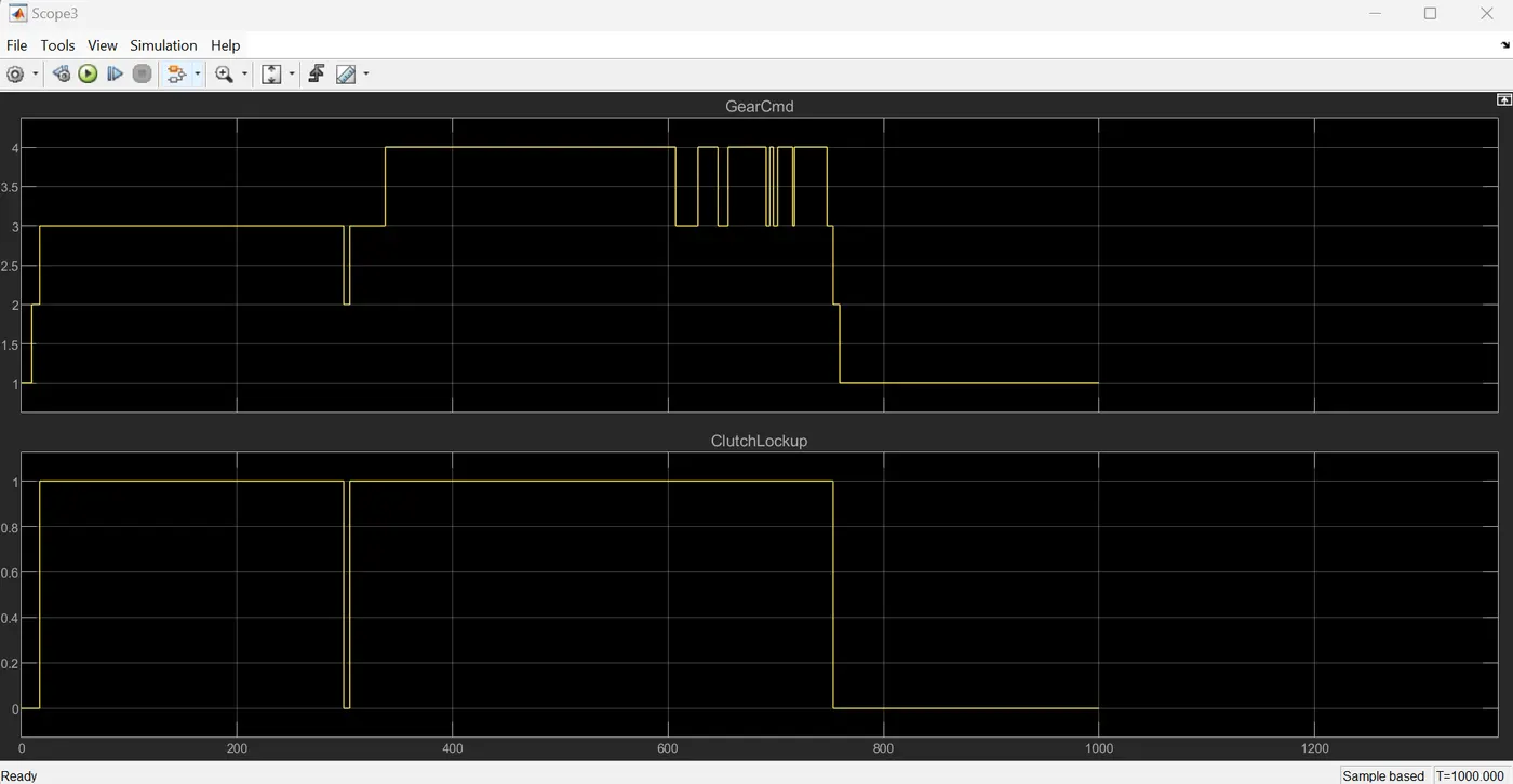
The two plots together represent the control strategy for a hybrid vehicle's transmission.
- The "GearCmd" plot specify the desired gear, while the "ClutchLockup" plot indicates when the clutch is engaged to facilitate gear shifts. The timing and coordination between the two signals are crucial for smooth and efficient gear changes.
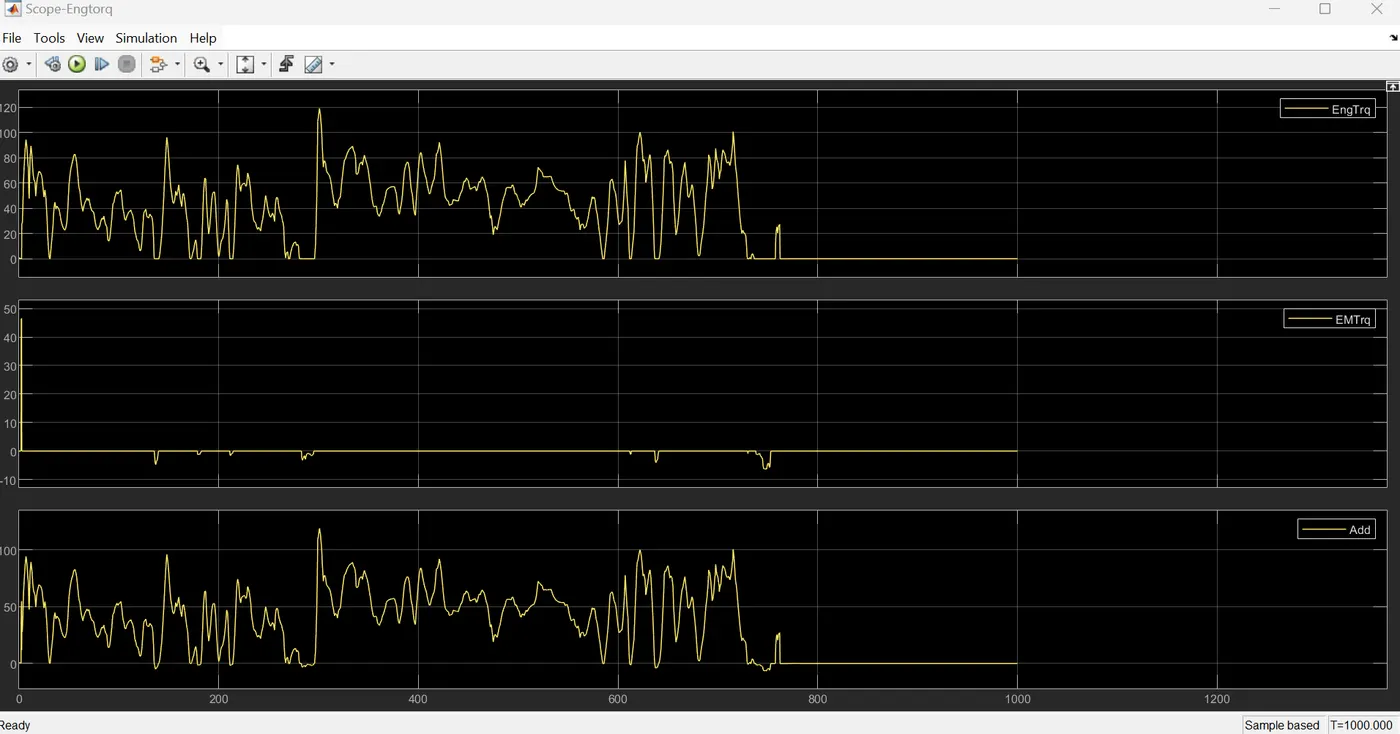
- The plot specified the torque produced by engine and torque produced by motor for the hybrid vehicle.
- The engine provides torque to drive the wheels, similar to a conventional vehicle. The electric motor is mechanically connected to the driveline and boosts the engine's power output. A mechanical coupler combines the torques from the engine and motor and sends it to the wheels.
- The last plot specifies the combine torque generated by both engine and motor in the given parallel (P1) hybrid vehicle model.
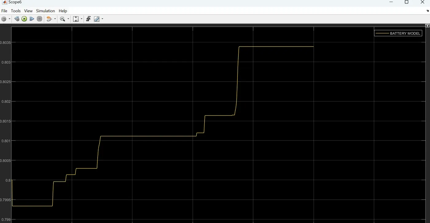
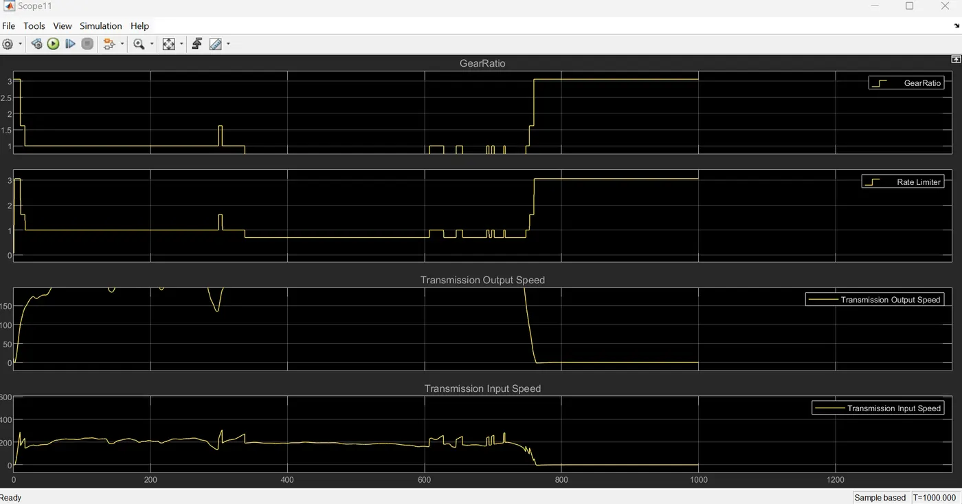
- The plots together represent the transmission control strategy for a parallel P1 hybrid vehicle.
- The "GearRatio" plot specify the desired gear ratio.
- The "Transmission Output Speed" and "Transmission Input Speed" plots might show the relationship between the input and output speeds, which can be affected by the gear ratio and other factors.
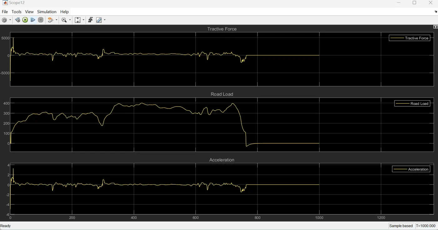
The three plots together represent the basic dynamics of a parallel P1 hybrid vehicle.
The "Tractive Force" is the net force acting on the vehicle, which is the difference between the "Tractive Force" and the "Road Load."
The "Acceleration" is related to the net force through Newton's second law of motion (F = ma).
The plot shows how the vehicle's acceleration is influenced by the balance between the tractive force and the road load.
- If the tractive force is greater than the road load, the vehicle will accelerate.
- If the tractive force is equal to the road load, the vehicle will maintain a constant speed.
- If the tractive force is less than the road load, the vehicle will decelerate.
In a parallel P1 hybrid vehicle, the tractive force can be provided by the internal combustion engine (ICE), the electric motor (EM), or a combination of both. The road load can vary depending on factors like road conditions, vehicle speed, and external forces.
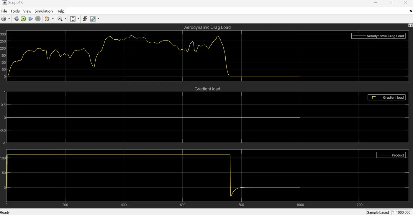
The three plots together represent the external forces acting on a parallel P1 hybrid vehicle.
- The "Aerodynamic Drag Load" and "Gradient Load" are two components of the total road load acting on the vehicle.
- The "Product" plot shows the combined effect of these two forces, which can influence the vehicle's acceleration and fuel consumption.
- The combined effect of aerodynamic drag and gradient load can be significant, especially on steep slopes or at high speeds.
- The relative importance of these two forces can vary depending on the driving conditions. For example, on a flat road at low speeds, aerodynamic drag might be the dominant factor. On a steep slope at high speeds, both aerodynamic drag and gradient load could be significant.
- The control system of a parallel P1 hybrid vehicle must be able to manage the combined effects of these two forces to optimize vehicle performance and fuel efficiency.
Conclusion:
The development of the forward energy-based fuel consumption model for the P1 hybrid vehicle has yielded significant insights into the hybrid vehicle's operational dynamics, performance, and efficiency. By leveraging the Honda Insight's motor and battery data from the ADVISOR database, this project has successfully demonstrated the advantages of hybrid technology over conventional vehicles.
The analysis revealed marked improvements in fuel economy during both urban (UDDS) and highway (HWFET) drive cycles, showcasing the hybrid vehicle's ability to optimize fuel usage while reducing emissions. Through a comprehensive examination of various operating parameters—including engine and motor speeds, torque, and battery state of charge (SoC)—the project provided a nuanced understanding of how hybrid systems adapt to driving conditions.
Overall, the project demonstrated the effectiveness of P1 hybrid vehicles in improving fuel efficiency and reducing emissions. The thorough analysis through physical modelling and visualization of simulation results highlights the operational benefits of hybrid technology providing a valuable framework for future research and development in hybrid vehicle systems.