Project 2
BACK DOOR WIRING HARNESS ROUTING
AIM: Route the wiring harness on the Given car body and prepare to flatten view drawing in CATIA V5. Application of all Packaging rules, Industry best practices studied in this course shall be demonstrated in design. Apply Protection coverings as required.
PACKAGING RULES AND ASSUMPTIONS:
- Provide Enough Clearance to the wiring harness with respect to the surrounding
- Avoid harness routing and clipping in the blind zone
- Provide additional slack to the harness according to the surrounding. 5-10% of slack
- Branch length should maintain at 50mm
- Minimum distance between the clip and nearest branching point should be 25mm
- Minimum distance between two breakouts should be 50mm
- Connector 1= C-776438-4
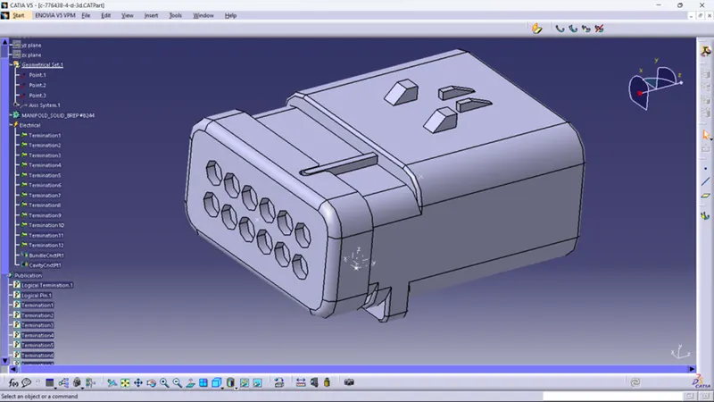
Create points on the bundle side and connector side cavity connection side.
Provided axis system on the connector connection side.
Defined as a connector in electrical part workbench.
Defined as a connector connection point.
Defined as a bundle connection point.
- Connector 2= C-DT06-2S
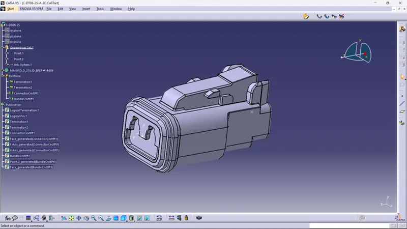
Create points on the bundle side and connector side cavity connection side.
Provided axis system on the connector connection side.
Defined as a connector in electrical part workbench.
Defined Connector connection point.
Defined Bundle connection point.
- P-Clamp
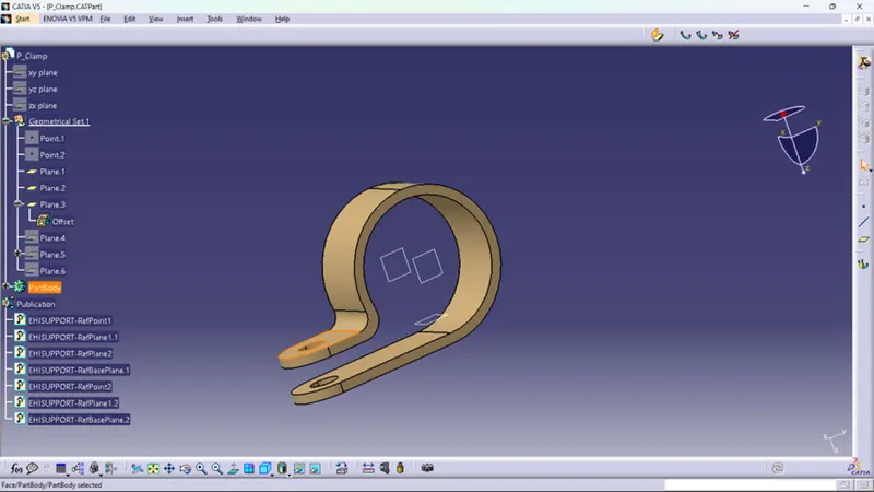
Defined Points on bundle entry and exit points.
Created planes for entry and exit side of p clamp.
Defined as support by providing entry, exit, and base points.
- Opened a New product file in the mechanical assembly workbench imported back door model.
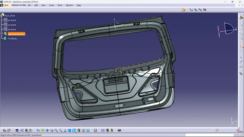
- Imported all connectors and clamps manipulated as required positions.
- Clamps placed with required direction.
- Click on the Geometrical bundle command by a convert to Electrical assembly
- After Converted Start Routing with Connectors
- Click Multibranch able to give the diameter of the bundle 10mm
- Bundle bend radius must have 1.4 times greater than bundle Día
- Slack is given additionally for avoiding clashes or any other errors
- Routing is done for the Licence plate and Tail Lamp connectors.
- Provided Cot Tube in Required places, 15-25 mm distance maintained from the connector end
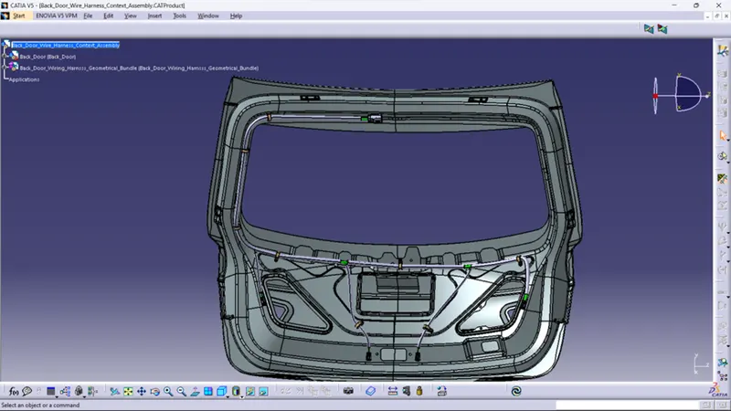
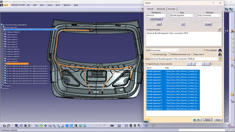
- Bundle segment Connection Checked Fully connected or not. It’s fully connected.
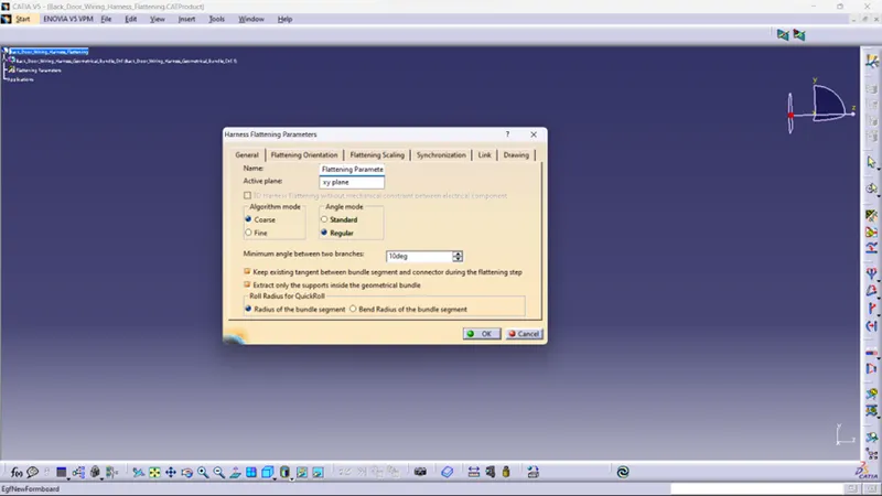
- Opened a new product file in Harness flattening and made parameters.
- Extract the Bundles from the Back door product file by using the extract command. For Tail Lamp Bundles
- Flattening is done by using the flattening command.
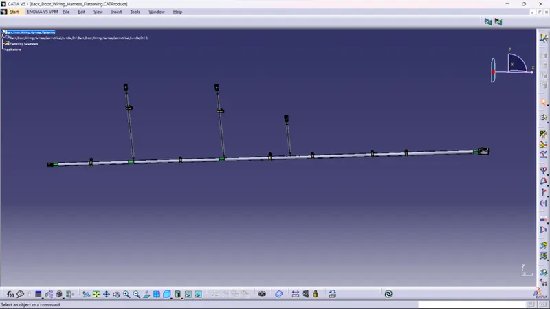
- Opened in a file in Drawing workbench imported flatten model in front view. Bill of material created for the tail lamp.
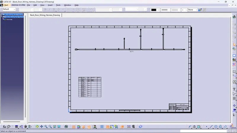
CONCLUSION:
- Back Door Wiring Harness Assembly Created by using CATIA V5
- After Completing this model. It has been verified or tested by Electrical Engineers. If this model Ok continue to Manufacturing Department