Project 2
1)
Aim - i) To Design Warehouse Building located in Chennai using STAAD Pro Connect Edition.
ii) Prepare a Design Basis Report for the project
iii) Create structural model using STAAD Pro Connect Edition
iv) Prepare DL, LL, WL and EQL load calculations as per IS 875 standards
Procedure -
i) Open Stadd Pro
ii) Click on Create New Project
iii) Set Unit as Metric
iv) Create Geometry by using given data
v) L = 50m
vi) B = 30m
vii) Eave Height = 9m
viii) Roof Slope = 1 in 12
i) Roof Slope Calculation -
Roof Slope = 1 in 12 ......................( given )
`x/(b/2) = 1/12`
`therefore X = 1.25 m`
where x = central ridge ht
b = width
The height of central ridge is x = 1.25 m
total ht = 9 + 1.25
= 10.25 m
ix) Model is prepared in STAAD Pro.
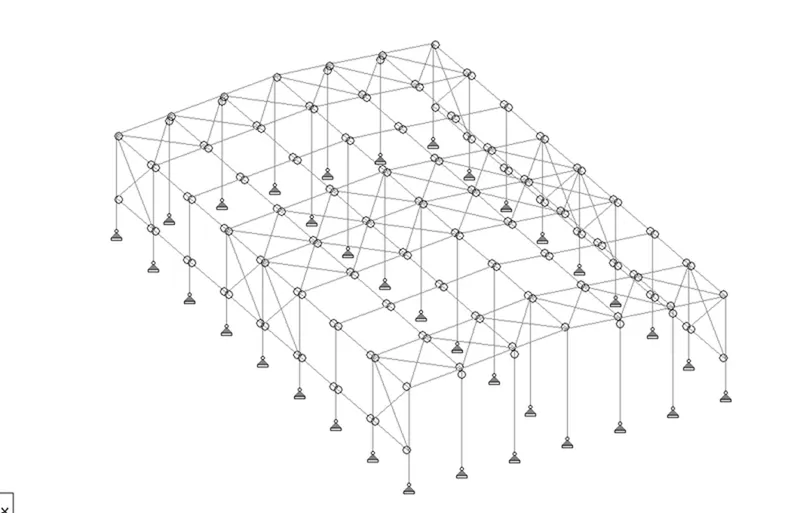
x) Section properties and Materials are applied to all the member
xi) Releases and specifications are applied.
xii) Support conditions are applied.
2) Calculaion of Loading
A) Dead Load
Dead Load on Rafter
i) Weight of Roof Sheet = 5 Kg/m2
ii) Weight of Purlin and sag rods = 5 Kg/m2
iii) Additional weight = 5 Kg/m2
Total weight of rafter = 15 Kg/m2
iv) Dead load on rafter = 15 x 10 x 8 = 1200 N/m = 1.2 kN/m
v) Dead Load on Purlin = 10 x 10 x 8 = 800 N/m = 0.8 kN/m
vi) Mezz Slab self-weight (150 mm thk slab) = 0.15 x 25 kN/m3 = 3.75 kN/m2
vii) Floor Finishes and additional load on Mezz Floor = (150 + 500) kg/m2 = 0.65 kN/m2
viii) Weight of 230mm thick brick wall (4-meter height) on Mezz floor = 20 kN/m3 x 0.23 x 4 = 18.4 kN/m
B) Live Load
i) Live Load on Roof = 0.75 Kn/m^2
ii) UDl on Rafter = 0.75 x 6 = 4.5 Kn/m
iii) Eave Gutter = (250 x 250 x 10 mm )
iv) Load due to wt of water in gutter = 0.25 x 0.25 x 0.010 x 6
= 3.75 Kn
C) Wind Load
Basic wind speed = 50 m/s for chennai
K1 - 1.00
K2 - 1.05 (Terrain Catogory-1. Building height at eaves = 10.50 m)
K3 - 1.00
K4 - 1.00 (For other structures)
Coefficient of cyclonic wind may be taken as 1,
Kd -0.9
Ka (Rafter) - 0.8 or as per tributary area.
Ka (Column) - 0.8245 or as per tributary area.
Ka (Purlin) - 0.9721 or as per tributary area.
Ka (Side Runner) - 0.978 or as per tributary area
Kc -0.9
Design wind pressure = pd = kd x ka x kc x 0.6 x (Vb x k1 x k2 x k3 x k4)2 = 0.652 kN/m2
But should not be less than 0.7 Pz = 0.7 x 1.006 = 0.704 kN/m2
Cpe - As per table 5 & 6 of IS: 875 (Part 3) – 2015
h/w = 10/60 = 0.6
L/w = 170/60 = 2.83
Cpe On wall:
|
Direction |
A |
B |
C |
D |
|
0 deg. |
0.7 |
-0.25 |
-0.6 |
-0.6 |
|
90 deg. |
-0.5 |
-0.5 |
0.7 |
-0.1 |
Cpe On Roof:
Roof angle = 2.86
|
Direction |
EF |
GH |
EG |
FH |
|
0 deg. |
-0.86 |
-0.4 |
||
|
90 deg. |
-0.8 |
-0.4 |
Cpi = 0.2
Wind Load on Columns = (Cpe – Cpi) x A x Pd
Wind about X Direction + Cpi = (0.7 – 0.2) x 8 x 0.704 = 2.816 kN/m on Wall A
Wind about X Direction + Cpi = (-0.25 – 0.2) x 8 x 0.704 = -2.534 kN/m on Wall B
Wind about X Direction + Cpi = (-0.6 – 0.2) x 6.75 x 0.704 = -3.802 kN/m on Wall C & D
Wind about X Direction - Cpi = (0.7 + 0.2) x 8 x 0.704 = 5.069 kN/m on Wall A
Wind about X Direction - Cpi = (-0.25 + 0.2) x 8 x 0.704 = -0.282 kN/m on Wall B
Wind about X Direction - Cpi = (-0.6 + 0.2) x 6.75 x 0.704 = -1.9 kN/m on Wall C & D
Wind about Z Direction + Cpi = (-0.5 – 0.2) x 8 x 0.704 = -3.942 kN/m on Wall A
Wind about Z Direction + Cpi = (-0.5 – 0.2) x 8 x 0.704 = -3.942 kN/m on Wall B
Wind about Z Direction + Cpi = (0.7 – 0.2) x 6.75 x 0.704 = 2.376 kN/m on Wall C
Wind about Z Direction + Cpi = (-0.1 – 0.2) x 6.75 x 0.704 = -1.425 kN/m on Wall D
Wind about Z Direction - Cpi = (-0.5 + 0.2) x 8 x 0.704 = -1.689 kN/m on Wall A
Wind about Z Direction - Cpi = (-0.5 + 0.2) x 8 x 0.704 = -1.689 kN/m on Wall B
Wind about Z Direction - Cpi = (0.7 + 0.2) x 6.75 x 0.704 = 4.276 kN/m on Wall C
Wind about Z Direction - Cpi = (-0.1 + 0.2) x 6.75 x 0.704 = 0.475 kN/m on Wall D
Wind Load on Rafters = (Cpe – Cpi) x A x Pd
Wind about X Direction + Cpi = (-0.86 – 0.2) x 8 x 0.704 = -5.970 kN/m on Side A Rafter
Wind about X Direction + Cpi = (-0.4 – 0.2) x 8 x 0.704 = -3.378 kN/m on Side B Rafter
Wind about X Direction - Cpi = (-0.86 + 0.2) x 8 x 0.704 = -3.716 kN/m on Side A Rafter
Wind about X Direction - Cpi = (-0.4 + 0.2) x 8 x 0.704 = -1.125 kN/m on Side B Rafter
Wind about Z Direction + Cpi = (-0.8 - 0.2) x 6.75 x 0.704 = -4.752 kN/m Side C Rafter
Wind about Z Direction + Cpi = (-0.4 - 0.2) x 6.75 x 0.704 = -2.851 kN/m Side D Rafter
Wind about Z Direction - Cpi = (-0.8 + 0.2) x 6.75 x 0.704 = - 2.851kN/m Side C Rafter
Wind about Z Direction - Cpi = (-0.4 + 0.2) x 6.75 x 0.704 = -0.950 kN/m Side D Rafter
D) Seismic Load
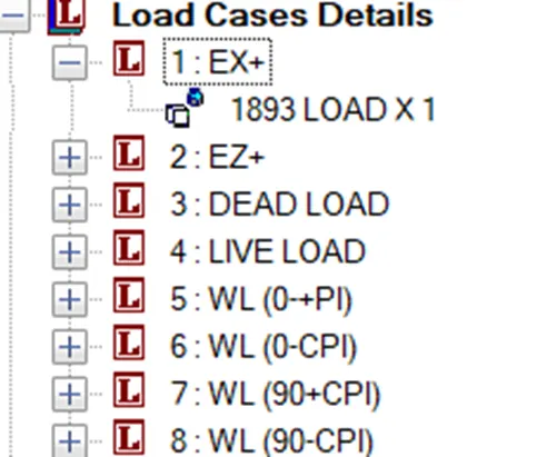
As per IS: 1893 - 2016
Seismic zone - III - Z = 0.16
Rf - 4.0
I - 1.0
SS - 3.0
25% of Live Load on roof considered for calculation of seismic forces.
100% of collateral load on roof considered for calculation of seismic forces.
50% of (Live load + Collateral load) on mezzanine floor considered for calculation of seismic forces.
100% of Dead load considered for calculation of seismic forces.
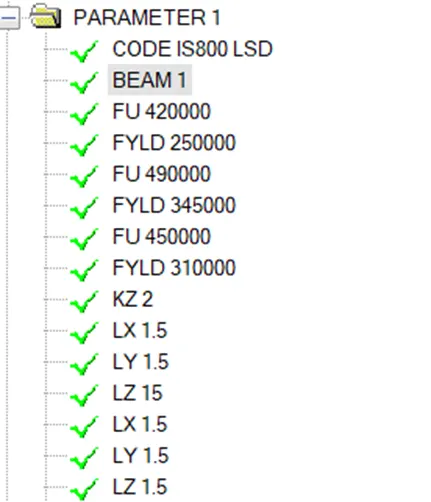
3) Design Parameters:
IS 800 LSD
FYLD = 345000 for Portal frame and Mezz Beams
FYLD = 250000 for Bracings
BEAM = -1
STP = 2 for welded sections
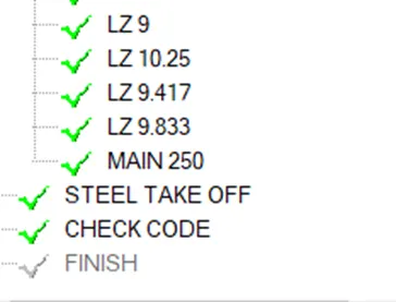
MAIN = 250 for tie beam
Ly = Lx = 1.5m for Rafter
Ly = Lx = 3.25m for Columns
Ly = Lx = 4.4m for columns supporting canopy
Lz = 11m for Internal columns
RATIO = 1
STEEL TAKE OFF
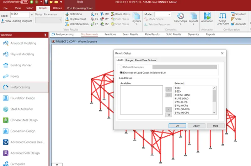
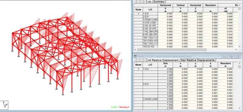
Result -
i) Once the ananlysis is done
ii) Click on Post Processing
B) Design of Foundation
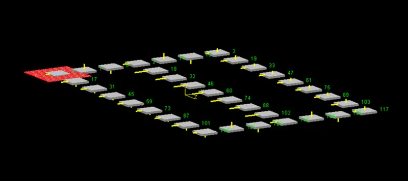
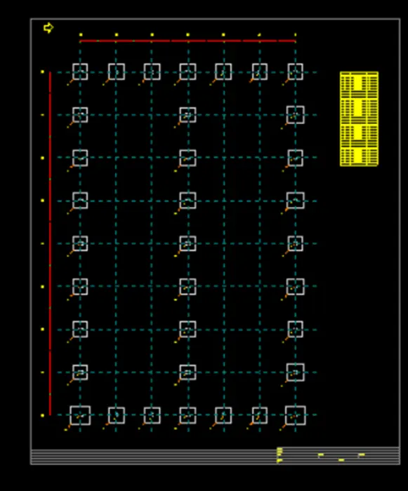
i) Import the file in stadd foundation
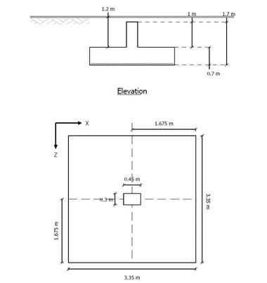
Check for Max/min Bearing Pressure
a) wt of soil above the footing
= (area of footing-Area of pedestel)xdepth of soil x unit weight of soil
= ((13.35x3.35) - (0·3×0.45)) x 1.2 × 18
=239.45 KN
b) self wt of footing.
= (vol of footing + vol of pedestall)x unit wt of concrete.
=((3.35×3·35x0·7)+(0.3×0.4x1))× 25
= 199.77 KN
Total load on footing= a+b+ Imposed load
= 239.45+ 199.47 + 1500
= 1939.26 kN
Section modulus of footing
Z=bd^2/6
3.35×(3.35)^2/6 = 6.26 mm^4
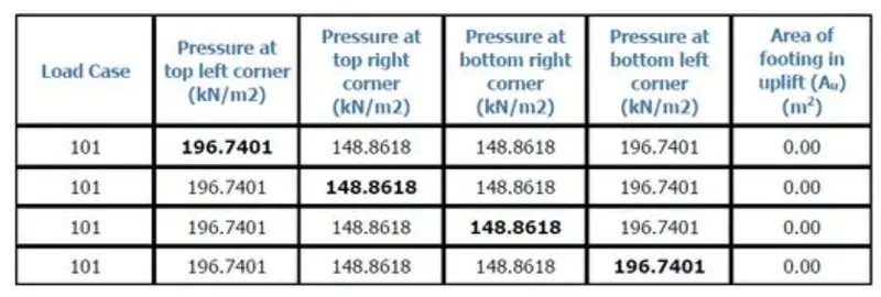
Maximam bearing pressure = P/A+M/Z
= 1939.26/(3.35+3.35)+150/6.26
= 196.7 kN/m^2
Min bearing Pressure
P/A+M/Z
M=148.8 kN/m^2
which is less than safe bearing capacity ie 200kN/m^2
Detailed Report has been added with all design structural elements
https://drive.google.com/file/d/1u_GHBiBA2YFJ5Yp-IClBTo1JPC3wzw63/view?usp=sharing
https://drive.google.com/file/d/1anng7IjTH4SOBtytAmt6OxPeFRs1xCdV/view?usp=sharing
2)
Design a simply supported gantry girder to carry electric overhead travelling crane
Given:
Span of gantry girder = 7 m
Span of crane girder = 9 m
Crane capacity = 250 kN
Self-weight of trolley, hook, electric motor etc. = 40 kN
Self-weight of crane girder excluding trolley = 100 kN
Minimum hook approach = 1.0 m
Distance between wheels = 3 m
Self-weight of rails = 0.2 kN/m
Aim - Design a simply supported gantry girder to carry electric overhead travelling crane.
Procedure -
i) Simply Supported Crane girder is designed in Excel Sheet
ii) Crane girder Pdf is attached below .
https://drive.google.com/file/d/1UxjmNmnZ4k33LXjx0mfOp7kRXhSaBQZp/view?usp