Project 2
AUTOMOTIVE BACK DOOR WIRING HARNESS ROUTING IN CATIA V5
AIM ; The aim of the project is to route the wiring harness on given automotive back door and prepare flatten view drawing using Catia V5.
OBJECTIVE
The obejective of the project is to route the wiring harness in the given backdoor and then create the flattened view of the routing and also create 2D drawing of the flattened view. The routing should be done by following all types of packaging rules as per industrial standards.
INTRODUCTION
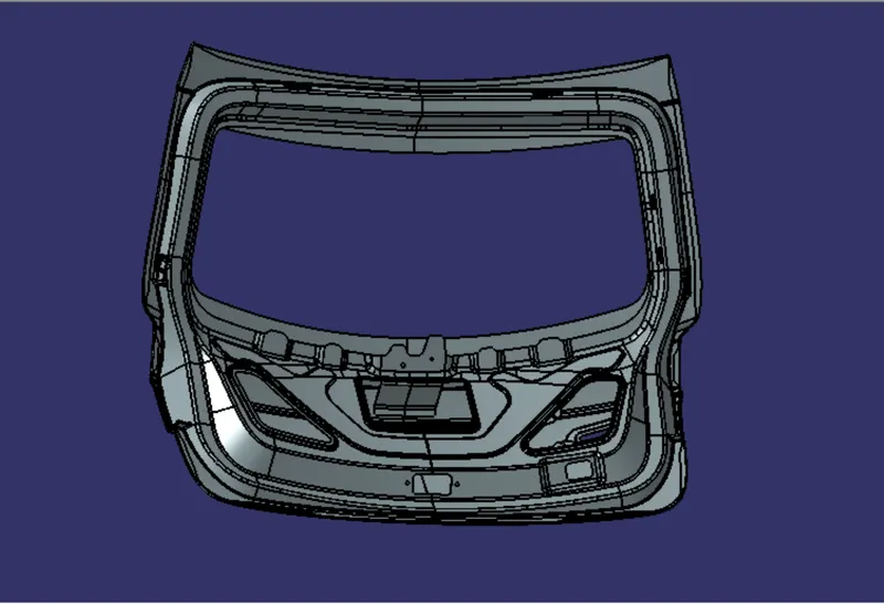
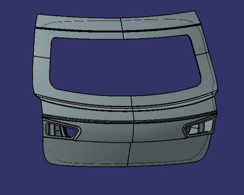
The wiring harness of a back door is an arrangement of wires, cables , connectors and terminals that controls the electrical system of the vehicle back door. The given backdoor requires following electrical components to which the wiring harness is to be routed.
- The back door consist of two tail lights in the two side , for the tail light of the back door we use two 8 pole connectors to connect them electrically.
- There is also one number plate light on the middle portion of the backdoor for that 2 pole conectors are used to connect them electrically.
- For the viper motor also we have used a 2 pole connector to connecting the motor electrically.
- Finally an interconnector is used to connect the backdoor wiring harness to the vehicle main wiring harness system.
- Fir tree clips are also used for the positive clamping and clearence management for the routing .
DESIGN CRITERIA AND PACKAGING ASSUMPTIONS FOLLOWED IN THE ROUTING
- The wiring harness roting shall provided ease in manufacturing , accesiblity, easy removal and easy maintenance .
- Routing through the small structured holes and openings shall be avoided
- Avoid the harness routing and clipping in the blind zones of the operator for the ease of service.
- Give proper dditional slack for the harness according to the surroundings and harness brnding requirements.
- And also ensure the routing have proper clearence with the surrounding parts
- Avoid routing over the bolts ,near to the bolted joints.
- Avoid harness routing near the sharp edges , if it is not possible then give proper protection for it.
- Maintain the proper distance between the two clips in a straight branch take it as 200 mm maximum.
- The use of two many sheet metal brackets should be avoided
- Ensure the branch length should be more than 50 mm
- Min distance between clip and branching is to be 25 mm.
- Minimum distance between two branch point should be 50mm.
PROCEDURE
STEP 1 - Creating context assembly
A context assembly is created which named as assy tail gate harness context and the all other components comes under context assembly , which is the main assembly . The context assembly consist of assy of tail gate and tail gate harness geometrical bundles.
STEP 2 - Define all the components as electrical component.
Define all the equipment like connectors , mounting equipments etc required for the routing as electrical component using electrical part workbench.
CONNECTORS
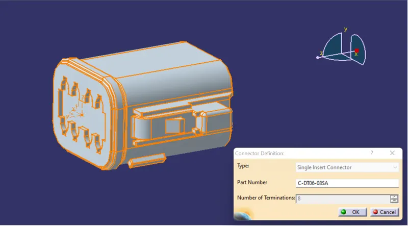
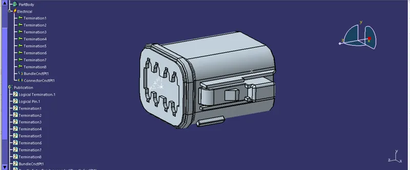
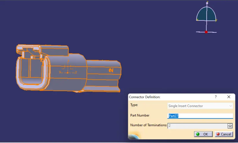
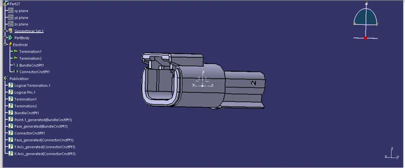
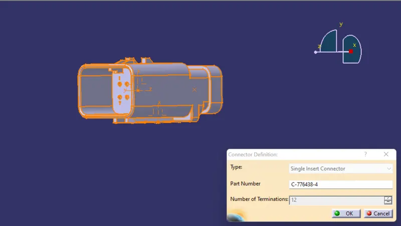
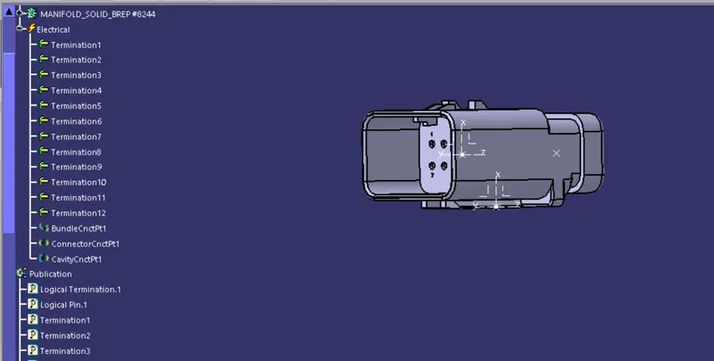
Define all the connectors as electical connector using electical part workbench and define its bundle connection point and connector connection point as shown below.
- 8 POLE CONNECTOR (C-DTO6-08SA)
- 2 POLE CONNECTOR
- 12 POLE CONNECTOR( C-776438-4)
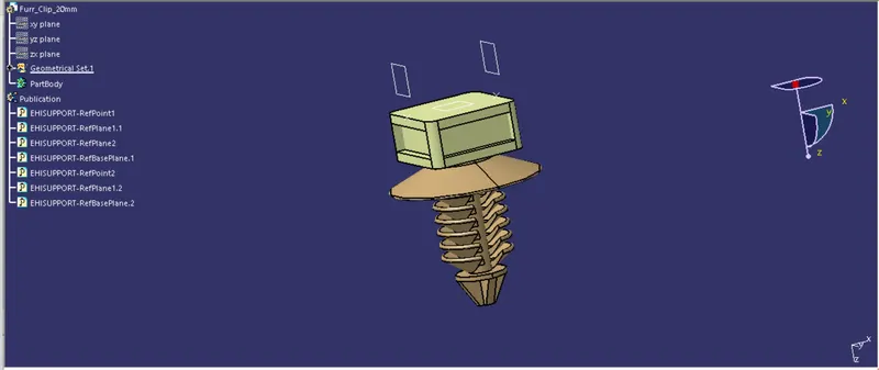
FIR TREE
Define the Fir tree as an electircal support define its bundle entry and exit point as shown below.
STEP 3 - Arrange the connectors at the respective positions.
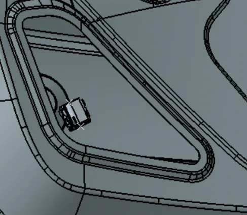
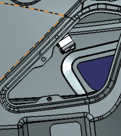
- The back door consist of two tail lights in the two side , for the tail light of the back door we use two 8 pole connectors to connect them electrically, and the connectors are placed as shown below
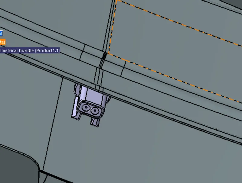
- There is also one number plate light on the middle portion of the backdoor for that 2 pole conectors are used to connect them electrically , they are placed as shown below
- For the viper motor also we have used a 2 pole connector to connecting the motor electrically and they are placed as shown below.
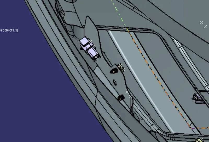
- An interconnector is used to connect the backdoor wiring harness to the vehicle main wiring harness system.
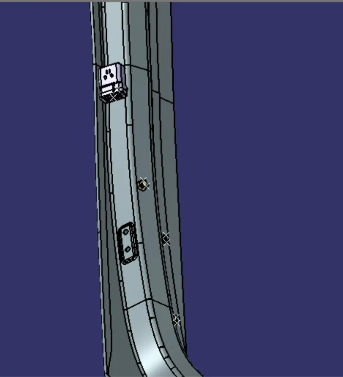
STEP 4 - Adding fir tree for wiring harness at required positions
Here we use about 20 fir tree clips are used for the positive claming and clearence management for the routing. as shown below
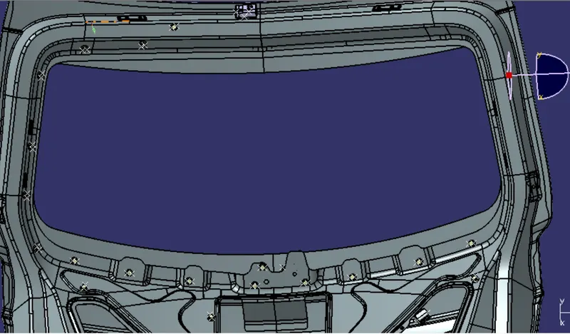
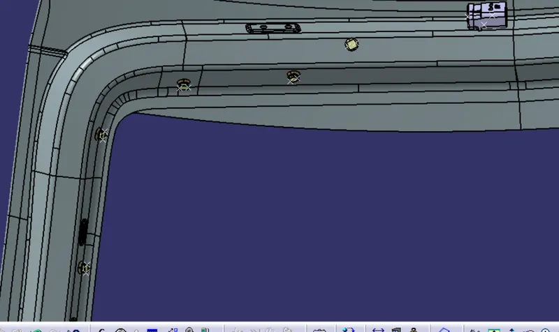
STEP 5 - Bundle routing starts from the interconnection connector
- After the arrangement of the all the equipments needed for the routing the bundle routing starts.
- The routing starts from the interconnection connector and it moves through the fir tree .
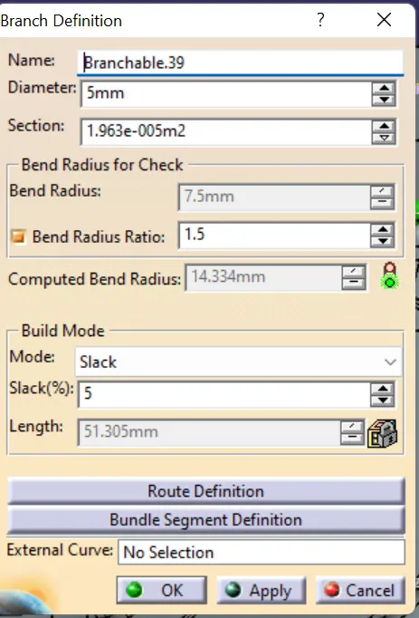
- The bundle diameter is taken as 10 and bend radius as 1.5 for these main branches as shown below,
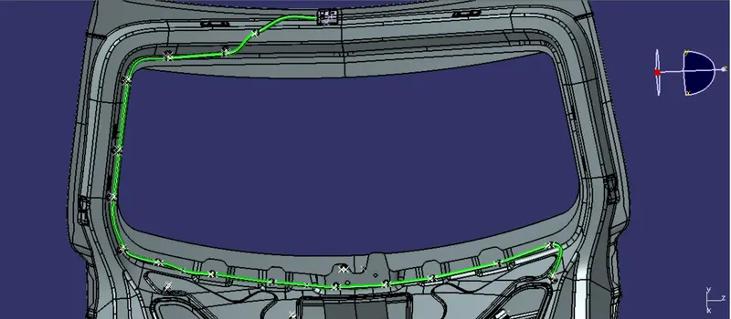
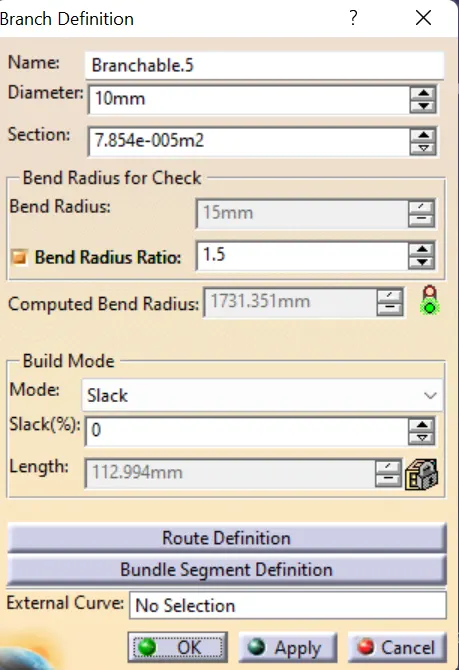
- After that create branch point at the respective positions where new sub branches are to be created .
- After the sub branches are created from the branch points , here sub branches are created for the connectors placed for tail light , wiper motor and number plate light.
- The diameter taken for sub branches are 5 mm and bend radius of 1.5 as shown below.
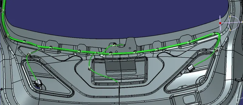
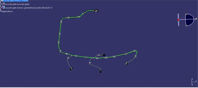
STEP 6 - Adding protective coverings to the bundle segment
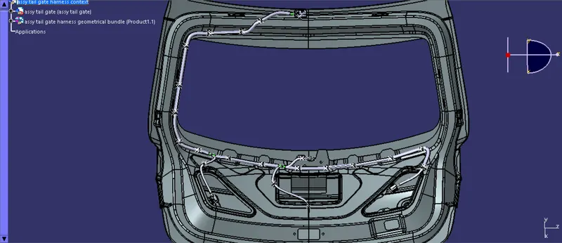
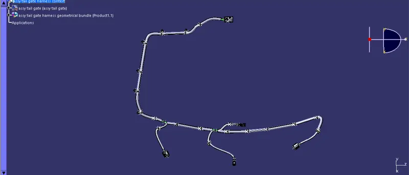
- After completion of therouting of bundle segment next step is to add protective coverings here we have used COT tubes for the protective covering of the bundle segment
- Here COT tubes of size 15mm , and 10mm are used mainly.
- And given end extrimity and start extrimity to the COT tubes by 15mm, as shown below
STEP 7 - Checking bundle continuity
- Bundle continuity is checked to confirm whether the bundles are fully connected or not.
- The bundle continuity is checking as per the images below
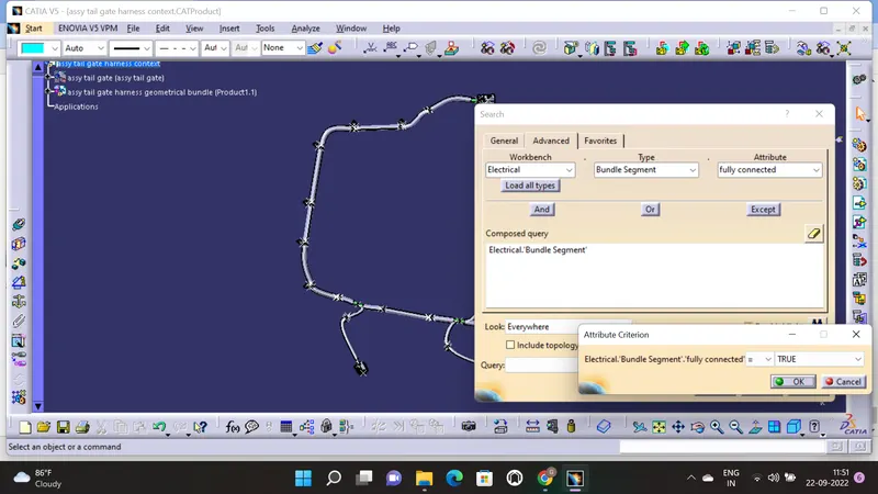
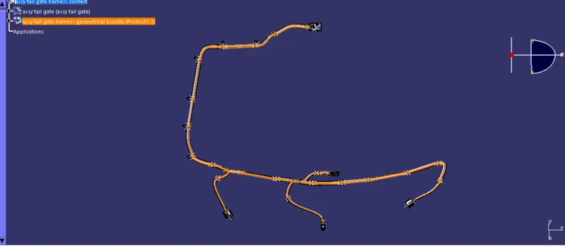
- Here we have given TRUE option and searched the result . all the bundle segment are highlighted and from this we can confirm that all the bundles are fully connected
STEP 8 - Creating flatten view of the tail gate harness geometrical bundle
- For this we want to switch to electrical harness flattening workbench
- At first create a new product file and save it in the same folder of tail gate harness context assembly
- Then add the flattening parameters as shown below
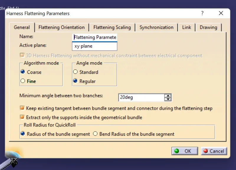
- Then extract the geometrical bundle to the flattening product assembly using extract option
- Then by selecting a plane we can start flattening , here i select one face of the interconnection connector as active plane for flatten.
- And we created the flatten view of the bundle segment and if requires we can arrange the flattened view by using various comands like rotation, roll, strighetn etc.
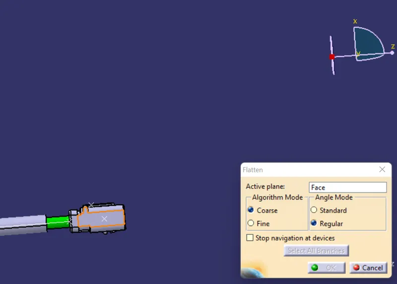
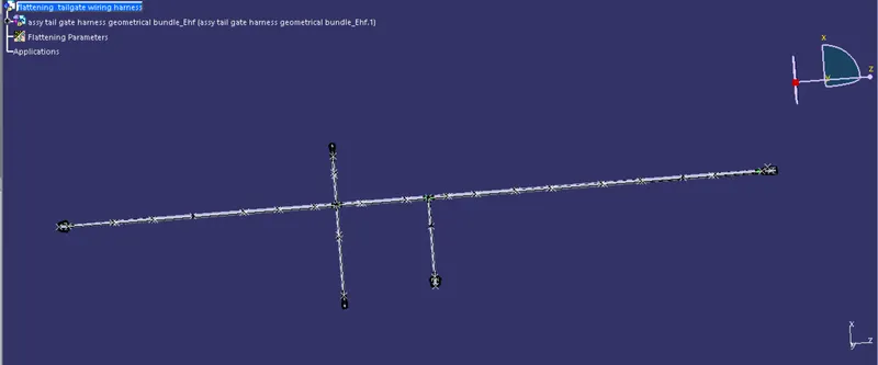
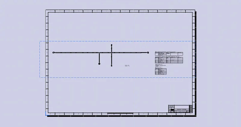
STEP 9 - Creating drawing of the flattened view
- For that create a new drawing file
- Then take the front view of the flattened view using front view options and arrange the drawing in the drawing sheet as shown below
- If require we can add the templates and bill of material to the sheet as shown below.
CONCLUTION
In this way the wiring harness is routed in the tail gate.