PRE-PROCESSING OF SUSPENSION AND WHEEL ASSEMBLY
PRE-PROCESSING OF SUSPENSION AND WHEEL ASSEMBLY
AIM :
To check for geometrical errors and mesh the given assembly with the given quality criteria. After meshing the thickness has to be assigned for mid surfaces. Use tetra elements to non-uniform thickness components and give the required connections after meshing.
FILE : Rear_Suspension_Assembly
QUALITY CRITERIA :
TRIA ELEMENTS (TYRE AND RIM) :
| Sl No. | QUALITY CRITERIA | VALUE |
| 1 | Target/Average length | 6.5 |
| 2 | Minimum Length | 5 |
| 3 | Maximum Length | 10 |
| 4 | Skewness | 45 |
MIXED ELEMENTS (For midsurface only) :
| Sl No. | QUALITY CRITERIA | VALUE |
| 1 | Target/Average length | 4 |
| 2 | Minimum Length | 2 |
| 3 | Maximum Length | 6 |
| 4 | Aspect | 3 |
| 5 | Warpage | 15 |
| 6 | Skewness | 45 |
| 7 | Jacobian | 0.7 |
| 8 | Minimum Quad Angle | 45 |
| 9 | Maximum Quad Angle | 135 |
| 10 | Minimum Tria Angle | 30 |
| 11 | Maximum Tria Angle | 120 |
FOR TERTRA ELEMENTS :
| Sl No. | QUALITY CRITERIA | VALUE |
| 1 | Tet-Collapse | 0.2 |
INTRODUCTION :
Suspension is the system of tires, springs, shock absorbers and lingages that connects a vechile to its wheels and allows relative motion between the two. Suspension systems must support both road holding/handling and ride quality, which are at odds with each other. It is important for the suspension to keep the road wheel in contact with the road surface as much as possible. There are two different types of suspensions that are used in automobiles : Dependent Suspension and Independent Suspension.
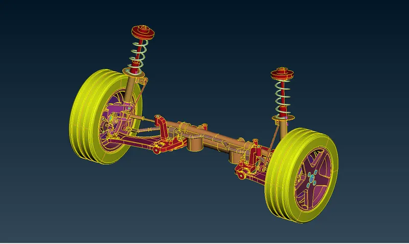
This project is based on the MacPherson Strut system. The components of this system are Coil Spring, Shock Absorber, Strut, Knuckle, Lower Ball Joint, Control Arm abd Bushings. The system is coupled with wheel assembly which includes Rim, Wheel hub, Disk Brake, Tire and Anti RollBar.
PROCEDURE :
- The model is opened in ANSA v20.1.4. The model was divided into 3 properties : tire, rim and components.
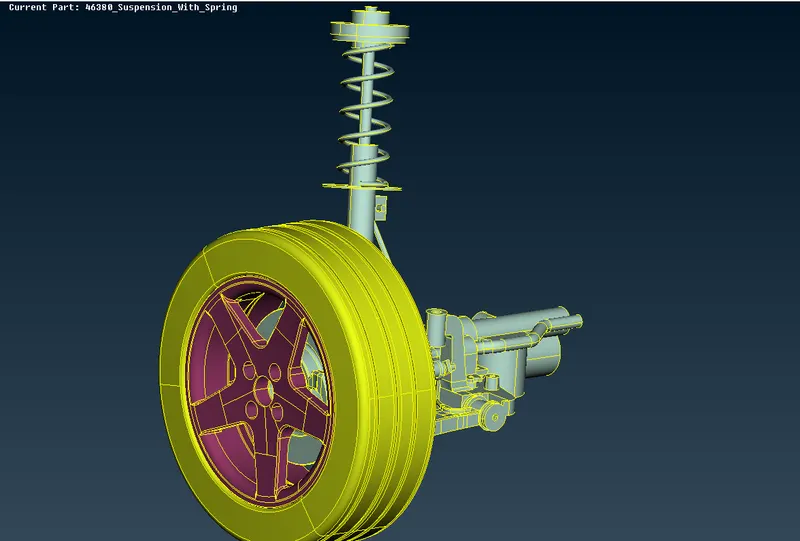
- The model was observed and it was clear that most of the components had to be meshing using Solid Meshing . So the first the Rim was checked for any geomertical errors by hiding all the rest of the parts. After clearing all the errors Batch Meshing was used to mesh the components in order reduce the time taken. Before that alle the required Quality Criteria and Meshing Parameters where inserted.
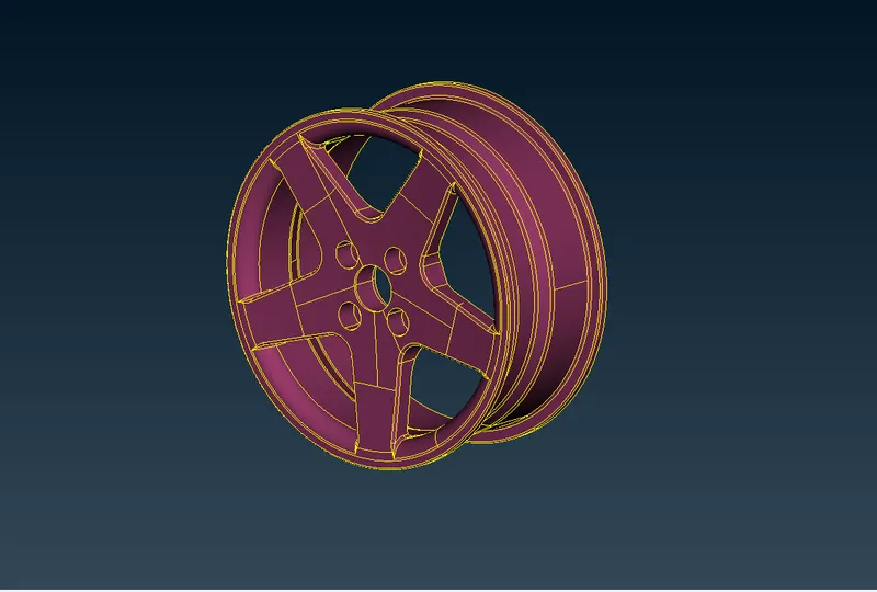
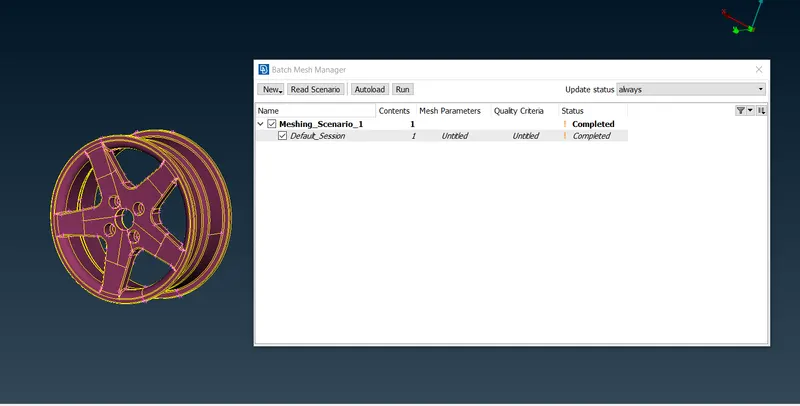
Below is the Meshed Rim removing all the Off Elements of meshed surface.
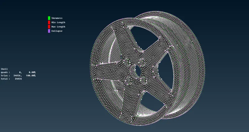
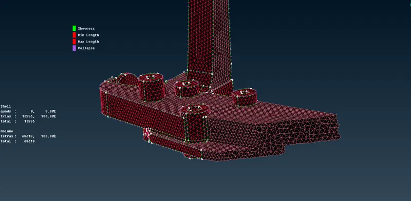
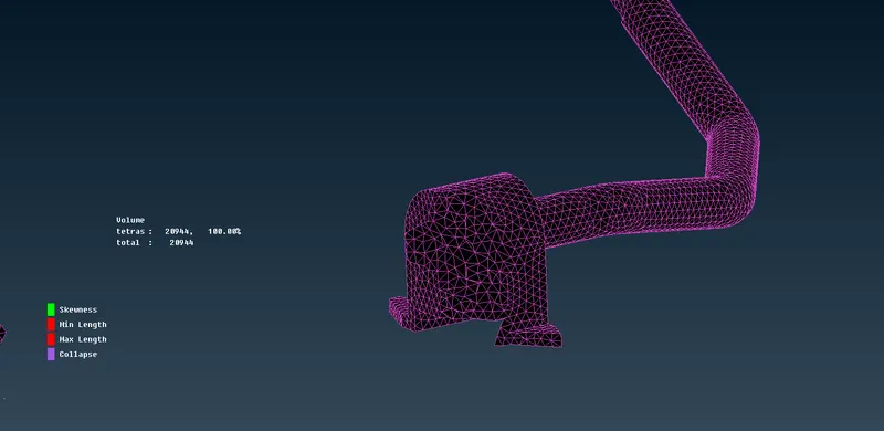
- Afther shell meshing of the rim, volume is defined from the Volume Meshing module . This was done by define>manual>auto and a new property PSOLID was created to define the voume. Tetra Rapid meshing was deplyed by selecting the defined unmeshed volume. And any Tet-Collapse were removed.
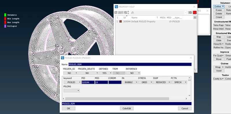
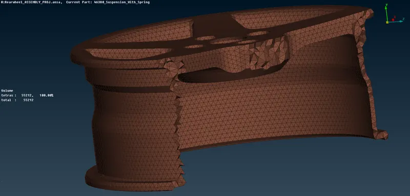
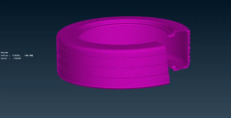
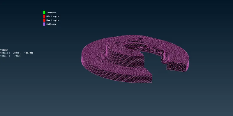
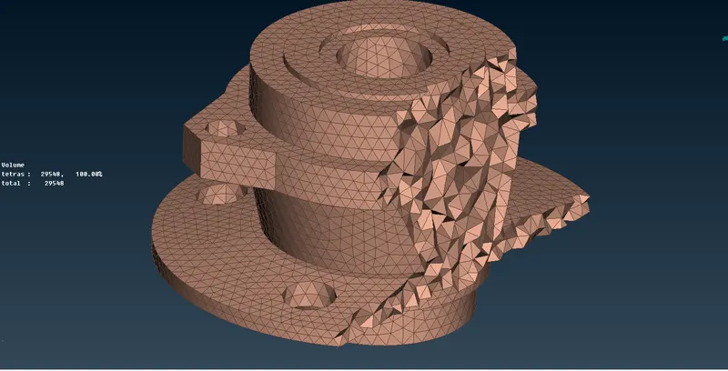
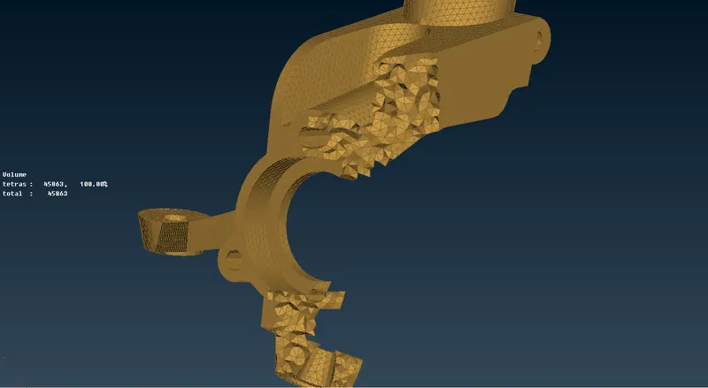
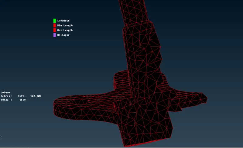
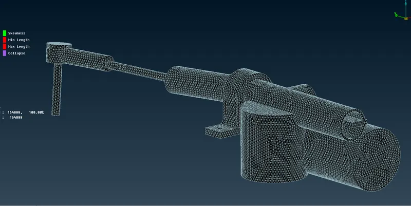
- In this similar manner rest of the components were Volume meshed (Tetra Rapid). The following images shows each of the components in its CAD and Volume Meshed form :
COMPONENT CAD MODEL VOLUME MESHED TIRE 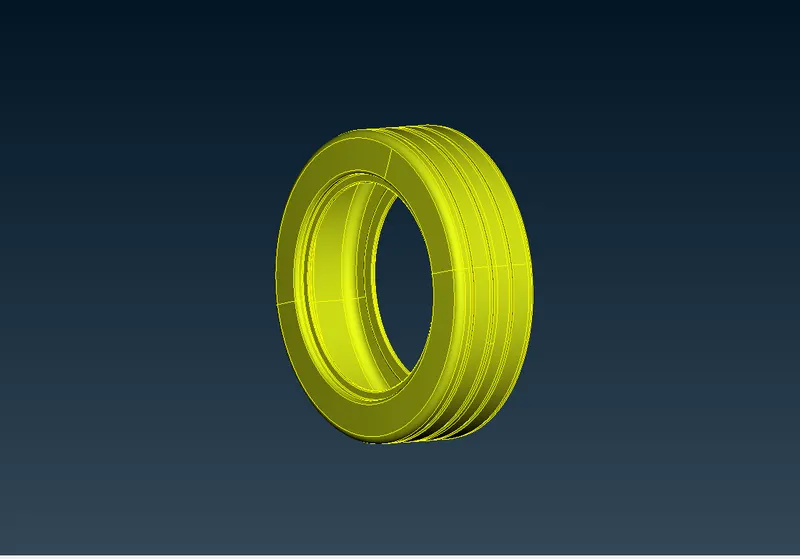
DISK BRAKE 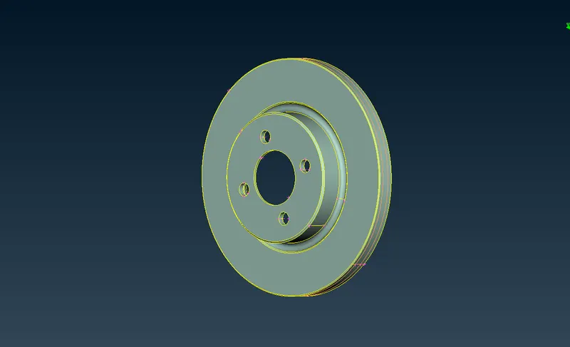
HUB 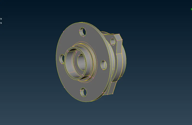
BRAKE CALIPER 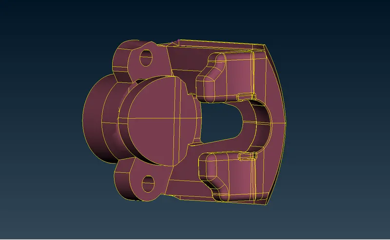
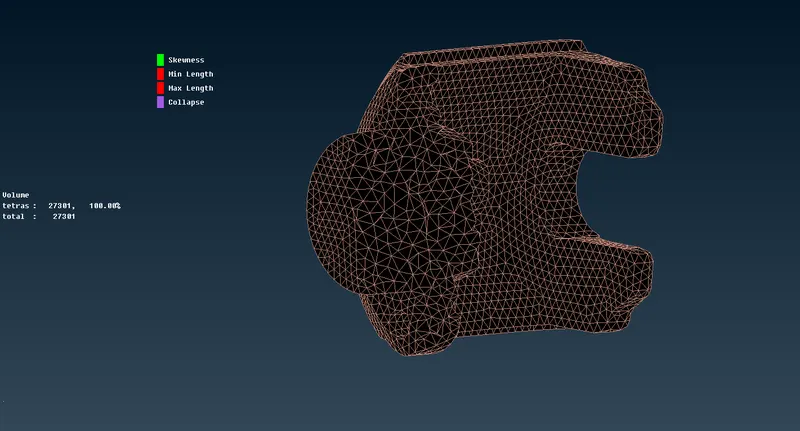
KNUCKLE 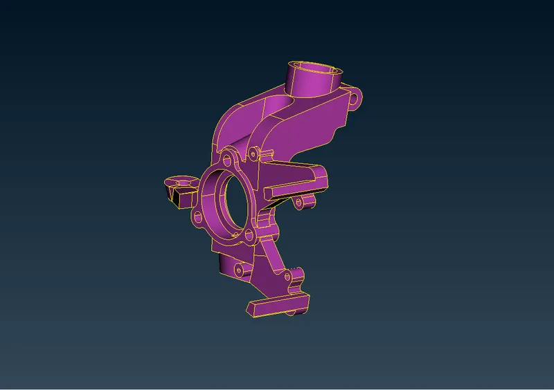
BALL JOINT 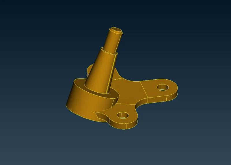
LOWER CONTROL ARM 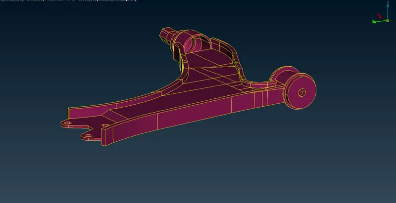

FRAME 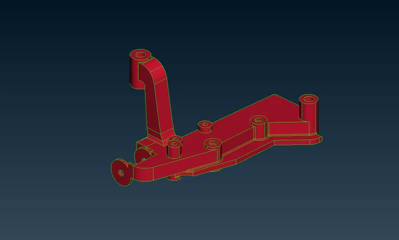
TIE ROD 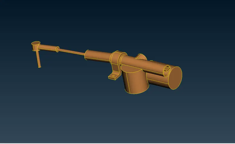
STABILIZER BAR 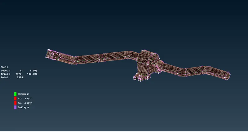
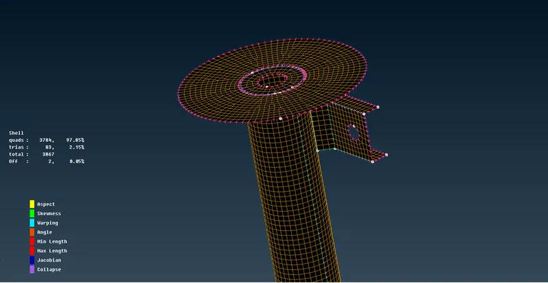
- The strut component of the suspension system has a uniform thickness. Therefore, mid-surfacing was done. The mid-surface was extracted manually using the offset option. Batch meshing was used to mesh the component. Seperate quality criteria and meshing parameters was loaded. All the Off elements were removed and mesh was finalized. A new PID was given with a thickness of 3mm.
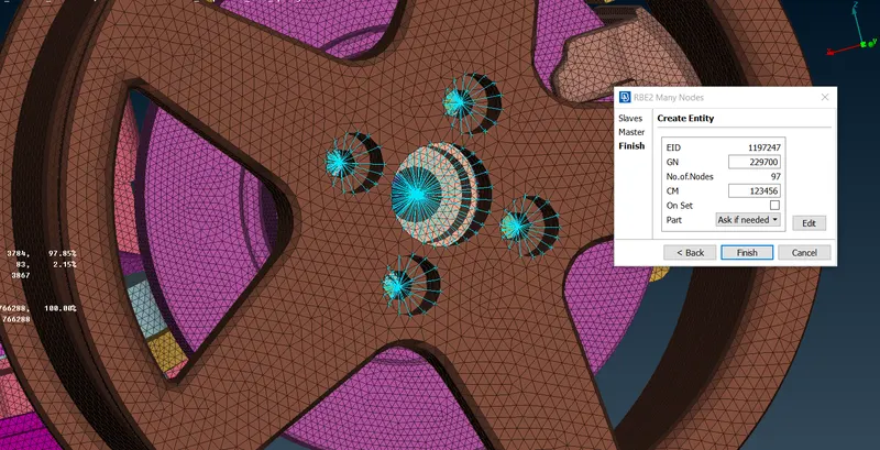
- The connections are available in the NASTRAN deck. RBE2 connections were deployed to connect the Rim and Wheel Hub. Similarly for other components. RBE2 two nodes are created by joining the Master Node of the other RBE2 in order to represent the stem or the body of the bolt.
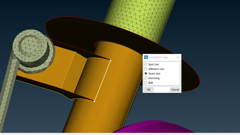
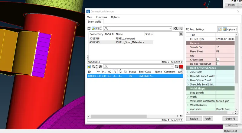
- For Strut element Seam weld was used. The curve was generated using Cons2curves under the Curves tab in the Topo. The curves is then converted into Seam link from the connectors option. Then Seam weld is defined by selecting the curve to the connection manager, and selecting the two parts P1 and P2 from Struct surfaces.
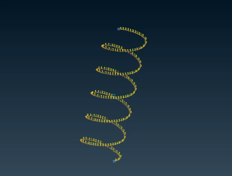
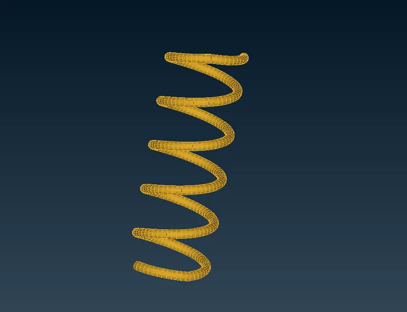
- The spring is generated using CBAR element from NASTRAN Deck. The middle curve of the spring was extracted using the curve>middle . COG of the spring curve from the topot mode was generated. From the NASTRAN deck, CBAR connection was selected, with orientaion with nodes checked. The COG point was selected as the orientation node with an element length of 5mm. A new PBAR property was created for the spring with cross-section radius of 5mm. Afterwards from the Quality Critera tab Line elements cross-section was checked which represents the spring in form of 3D elements.
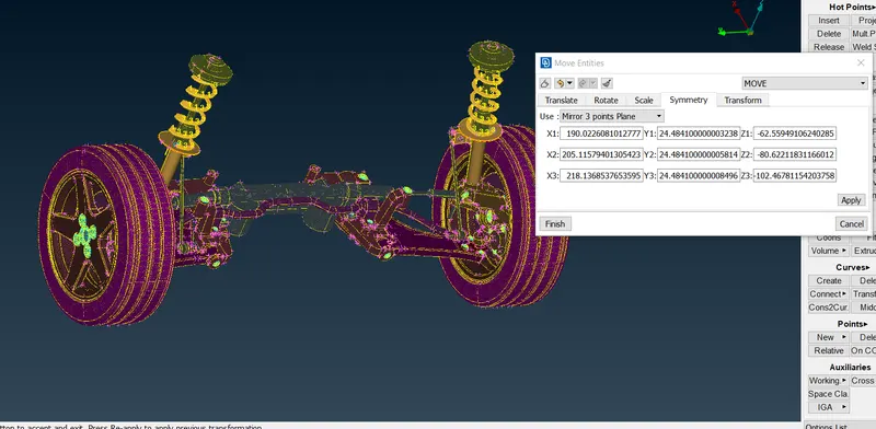
- Using the transform>copy all the entites were mirrored to form a complete suspension system. Mirror 3 point plane were selected in order to define the mirroring axis.
CONCLUSION :
- The Rear Suspenion and Wheel Assenmbly were mesed accoring to the given quality criteria and mesh parameters.
- Connection were appled accordingly.
- Most components had to be Volume meshed due to the non-uniform thickness. Batch meshing was used to mesh components with minimum Off elements.
- The strut component of the suspention was mid-surfaced as it was having uniform thickness of 3mm throughout. So with the help of Offset option it was mid-surfaced manually.
- The spring was modeled as a CBAR element by extracting the middle curve.
- Thus in this project all the components were meshed and connections were applied accordingly.