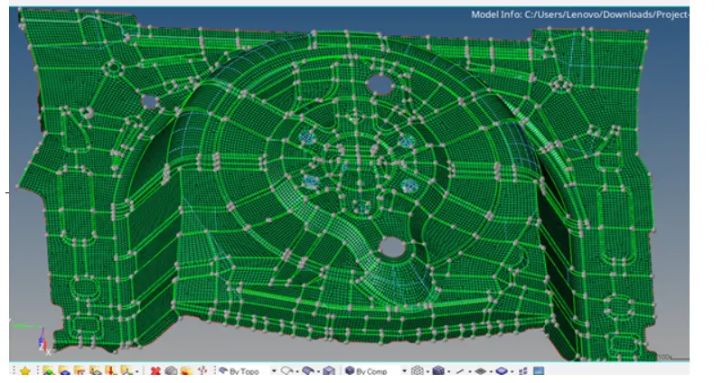
Project 2
OBJECTIVE:
- To mesh the model as per the given quality parameters and to assign the thickness for the model.
GENERAL DESCRIPTION OF THE PROCEDURE:
- The preprocessing of the model is done by extracting the midsurface. The midsurface is then meshed and assigned variable thickness in various areas.
- The mesh is the final representation of the oroginal model, which can be used for crash test analysis or stress strain analysis.
- The kind of the element depends on the type of analysis performed. Here we use 2d quad, tria elements.
- The elements have 5 DOF, 3 translational and 2 rotational.
- We use 2d elemnets here because 2d elements take lesser time to process the solution and the accuracy of the solution does vary a lot when compared to 3d elements.
CAD MODEL IMAGES :
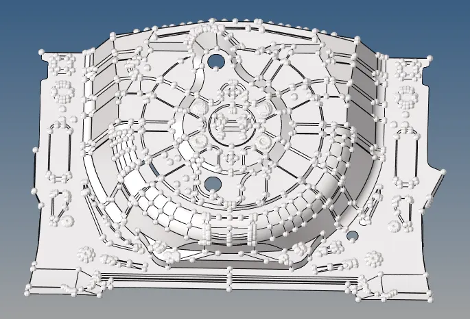
Fig(1). FLOORPANEL
PROCEDURE:
- The procedure mainly involves 3 steps, one is to clean the geometry of the model by importing the model and extraction of mid surface, Second is to mesh the model as per the given quality parameters, The final step is to assign thickness to the model. The following content describes this steps completetly,
- CLEANUP OF THE GEOMETRY OF THE MODEL AND MIDSURFACE EXTRACTION :
- The prelimnary step is to clean the geometry if the model and extract the midsurface, To do this first import the model into the hypermesh application using the import options.
- Once the model is imported, clean the geometry of the model by using tools available in geometry section by switching the model to topo mode. The model will appear as shown in the below figure when the model is switched to topo mode.
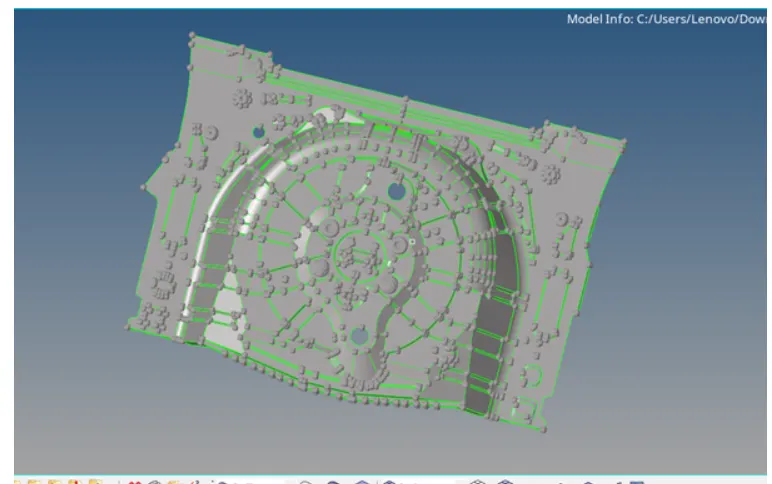
Fig(2). Floor panel in Topo mode
- Recreate the surfaces that get automatically deleted after importing the model, do all necessary actions that are required to clean the geometry of the model.
- The next important step is to extract the midsurface, The midsurface can be extracted manually or automatically.
- In case if the model has varying thickness, the midsurface has to be extracted manually by using offset option from surface edit panel.
- The floor panel i.e given model has same thickness throughout the entire body, so midsurface can be extracted automatically using automidsurface option from geometry panel.
- Some surfaces would get distorted while using automidsurface option, For such surfaces extract the midsurface manually.
- The following are the images of the midsurface and sequence of steps to generate midsurface.

Fig(3). Automidsurface panel

Fig(4). Offset option in surface edit panel
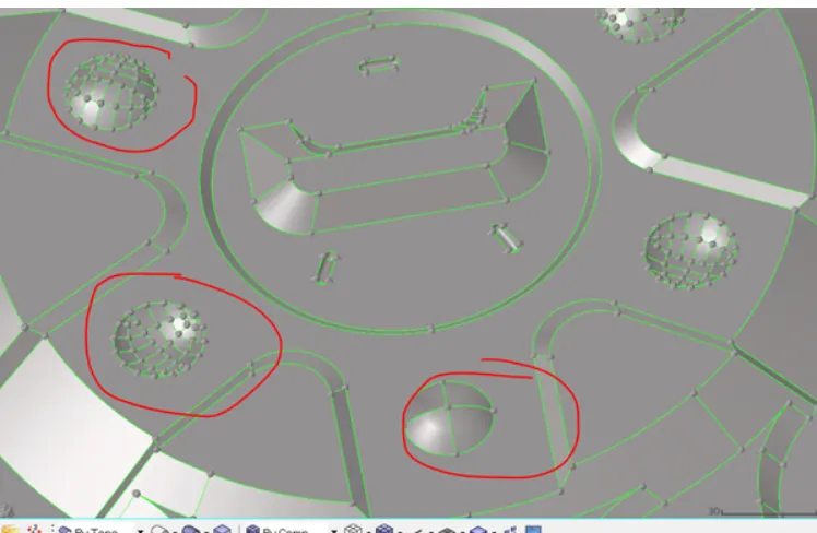
Fig(5). Features/ surfaces that have to be genarated using offset option/manually
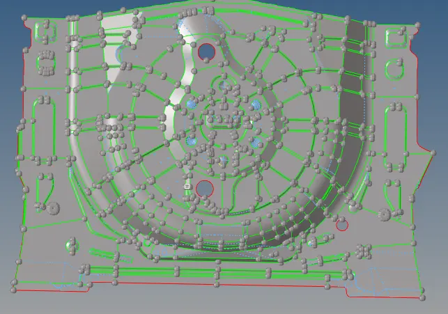
Fig(6). Generated midsurface
- Once the midsurface is generated, split the surfaces in the midsurface in the form of rectangles, pentagons for better capture of the surfaces and for better mesh flow
- Toggle all those feature lines and fillets that will fail for minimum length.
- Delete and refill the holes,surfaces that fail for minimum length.
- Check for duplicates in the component,if found delete them.The tools used for this procedure are,
- quickedit-toggle, This is used for suppressing the edges, lines.
- quickedit-split surface node-node , splitsurface node-line, these are used for splitting the surface.
- quickedit-Filler surface, this is used to fill the surfaces.
- quickedit-replace point, this option is used to replace points of a surfaces.
2. MESHING THE MODEL WITH THE GIVEN QUALITY PARAMETERS :
- The next step is to mesh the model as per the quality parameters. Before meshing the model, we have to specify the quality parameters.
- The quality parameters have to be entered in the criteria file settings in preferences option.
- The below is the set of images explaining this steps.The rootpath for quality parameters is Preferences-criteria file settings,
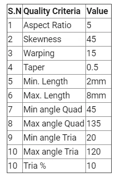
Fig(7). Given values of quality parameters
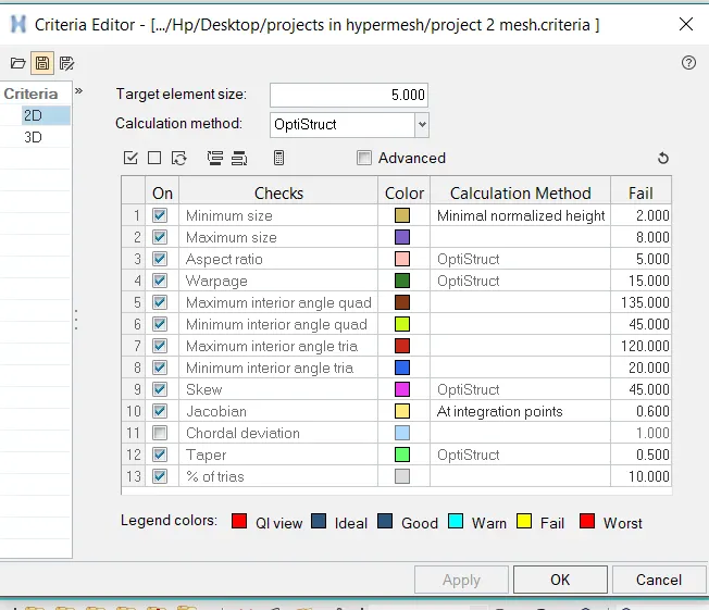
Fig(8). Criteria file editor
- Once all the quality parameters are filled, the model is ready to mesh. The meshing has to be done surface by surface to get a better mesh flow and quality.
- To perform 2d meshing on the model, select 2d-automesh- specify element length and type-click on mesh, here the target element length is 5 and the type of elements are mixed.
- The mesh can be enhanced by using various tools in the quality index available in the 2d panel, many tools are available to enhane the quality of the mesh and to improvise the flow.
- The following are some of the tools constantly used while meshing for fixing the quality of the elements,

Fig(9). 2d panel in hypermesh

Fig(10). Quality index panel

Fig(11). Automesh panel in 2d
- Place node- This tool is used to adjust the nodal loaction of the element.
- Smooth, This tool is used for uniform mesh flow.
- Drag tria, This tool is used to elimimate tria elements from the surface if possible and also to manipulate the location of the tria elements.
- Swap edge, This tool is used to change the location of the element.
- Element optimise, This tool enhances the elements qualtiy.
- Split quad, this is used to split the quad element.
- Combine tria, As the name itself suggests this tool is used to combine two tria elements.
- Smooth option is also available in 2d outside the qualtiy index panel, The following is the image of the smooth panel present in 2d.

Fig(12). Smooth option in 2d
- While meshing trias have to be eliminated from the surface as the trias are more stiffer when compared to quad elements. The tools such as swap edge,drag tria, combine tria can be used to eleminate the trias.
- Also rotating quads are also not prefered while meshing because they deviate the applied force in a unwanted direction resulting in the inaccuracy of the solution. Instead of these rotating quads, trias are prefered.
- There are some ground roles while handling these trias, they are listed as follows:
- No trias should touch each other.
- Trias facing in the opposite direction should be eliminated.
- There should not be back to bak trias.
- Trias shouldnot be present near the surface of the holes.
- Trias should not be present in the fillet regions.
- Trias concentration shouldnt be more, there should be considerable distance between them.The following are the examples tria region that have to be eliminated,
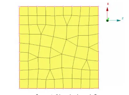
Fig(13). Mesh like this is undesirable
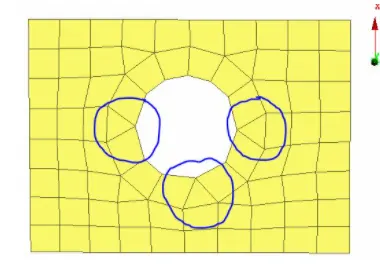
Fig(14). Trias near holes is not acceptable
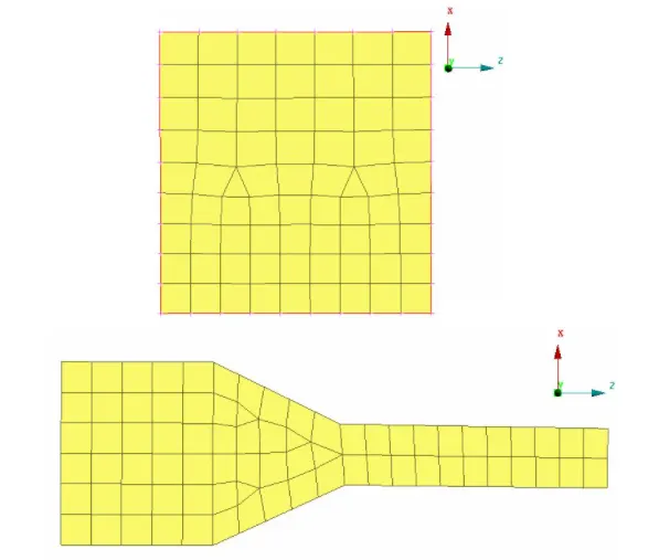
Fig(15). Better mesh flow and quality
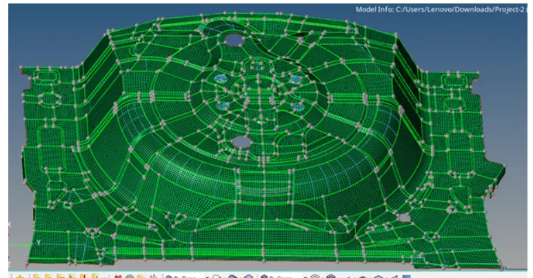
Fig(16). Final mesh generated on the surface
- Check for the free edges in the model and remove them if found, by using equivalence in edges options present in the tool panel.
- There shouldnot be any topological free edges, as they denote discontinuity in the mesh. We can also use replace node option to eleminate free edges.
- Final mesh after node replacement and equiavalence is as shown in the below image,
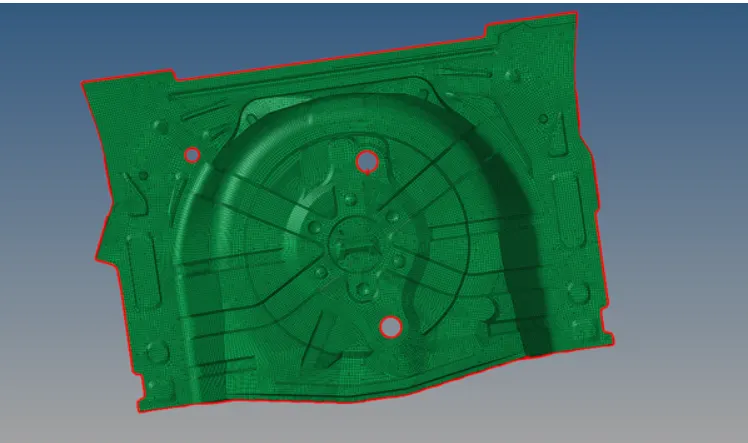
Fig(17).
- Turn on the 3d representation of the model to check how well the elements have captured the surface.
- Assign the thickness to the model by rightclicking on the component tab and create a property.
- Let the property be thickness, assign this property to the model.
RESULT :
The final image of the model after meshing is as shown below,