Preprocessing of Rear Suspension Assembly
The suspension is the system of tires, tire air, springs, shock absorbers, and linkages that connects a vehicle to its wheels and allows relative motion between the two. Suspension systems must support both road holding/handling and ride quality, which is at odds with each other. The tuning of suspensions involves finding the right compromise. It is important for the suspension to keep the road wheel in contact with the road surface as much as possible because all the road or ground forces acting on the vehicle do so through the contact patches of the tires. The suspension also protects the vehicle itself and any cargo or luggage from damage and wear. The design of the front and rear suspension of a car may be different. The Rear suspension of a vehicle performed the same general function as the front Suspension, but the specific construction is typically quite different.
AIM:
The main objective of this project is to perform the volume mesh and the connection to the given Rear suspension of a car as per the given Industrial Quality criteria by using the ANSA Pre-processor.
For Mid-surface for structural components:
|
S.No |
Quality Criteria |
Value |
|
01 |
Target/Average length |
4 |
|
02 |
Minimum length |
2 |
|
03 |
Maximum length |
6 |
|
04 |
Warpage |
15 |
|
05 |
Aspect ratio |
3 |
|
06 |
Skewness |
45 |
|
07 |
Jacobian |
0.7 |
|
08 |
Minimum quad angle |
45 |
|
09 |
Maximum quad angle |
135 |
|
10 |
Minimum tria angle |
30 |
|
11 |
Maximum tria angle |
120 |
For Surface mesh of Structural components:
|
S.No |
Quality Criteria |
Value |
|
01 |
Target/Average length |
4 |
|
02 |
Minimum length |
2 |
|
03 |
Maximum length |
6 |
|
04 |
Skewness |
45 |
For Surface mesh of Tyre and Rim:
|
S.No |
Quality Criteria |
Value |
|
01 |
Target/Average length |
6.5 |
|
02 |
Minimum length |
5 |
|
03 |
Maximum length |
10 |
|
04 |
Skewness |
45 |
For Volume mesh:
|
S.No |
Quality Criteria |
Value |
|
01 |
Tet-collapse |
0.2 |
Methodology:
To achieve the Volume mesh and connection in a Rear suspension by following the steps below,
- Importing the file
- Geometry check
- Thickness Measurement and Analysis of the parts
- Setting PIDs
- Mid-surface Generation
- Surface meshing
- Volume meshing
- Generate Connection
Rear Suspension:
The suspension is the system of tires, tire air, springs, shock absorbers, and linkages that connects a vehicle to its wheels and allows relative motion between the two. Suspension systems must support both road holding/handling and ride quality, which is at odds with each other. The tuning of suspensions involves finding the right compromise. It is important for the suspension to keep the road wheel in contact with the road surface as much as possible because all the road or ground forces acting on the vehicle do so through the contact patches of the tires. The suspension also protects the vehicle itself and any cargo or luggage from damage and wear. The design of the front and rear suspension of a car may be different. The Rear suspension of a vehicle performed the same general function as the front Suspension, but the specific construction is typically quite different.
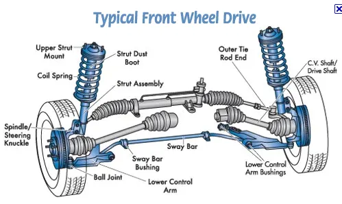
Components in the Rear suspension:
- Tire
- Rim
- Caliper
- Frame
- Ball joint
- Hub
- Steering Knuckle
- Lower control arm
- Sway bar
- Strut Assembly
Methodology:
1.Import the CAD file:-
- Open the latest version of ANSA.
- Import the cad geometry files through file > open or Ctrl + O.
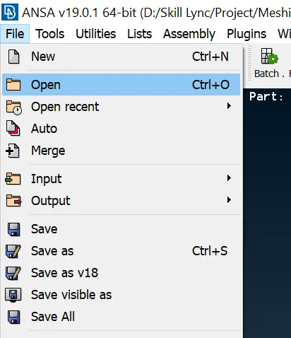
- Download the file and open it
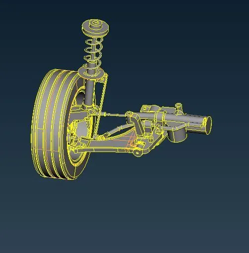
Fig. 1.0 Initial model
2.Geometry Checks:-
- Perform Topo, before ready for geometry checks
- The geometry checks process is used to identify the topo errors and fix it
- Geometry error process - Tools>>Checks>>Geometry>>Execute
- After checks, the geometry, If there is an error is present then the check bar will be shown the error with its type, message code, entity, ID, and reason like cracks, triple cons, collapsed cons, needle face, etc., and also shown if the error has been by auto fix itself that’s a great advantage for us.
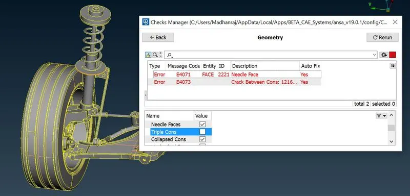
Fig. 2.0 Check for G-Errors
- If the error has been able to clear with the use of auto fix then,
- We have to done with ~ ctrl+A to select the whole errors then right-click the mouse and fix it. After the problem has been resolved then the check manager will show the execution is 100% like below.,
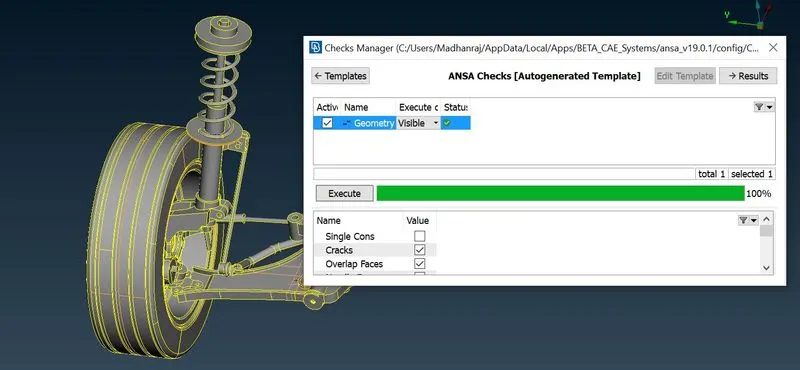
Fig. 2.1 After Fix the errors
3.Assign PID's to parts:-
- The PID is used to create a property of a particular part.
- Check the property, which is created before.
- Identify the part and assign the name as per the model.
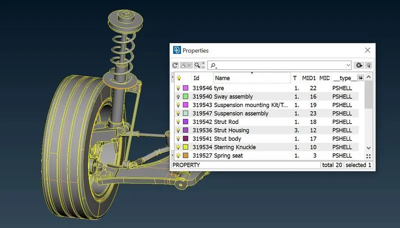
Fig. 3.0 Create PID
4.Mesh Generation:-
👉 For Tyre and Rim:
- Tyre doesn't have a thickness, so here we can perform the surface mesh and volume has to been created.
- For generating Volume, the mesh should be in Tria element, so the mesh is tria.
- For surface mesh as per our requirements, we can choose either batch or manual mesh type.
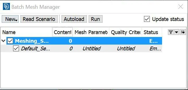
Fig. 4.0 Batch Mesh
- Batch Mesh - Ctrl+B >> New >> Meshing scenario >> Select the parts >> Assign the Mesh parameters and Quality criteria >> Run.
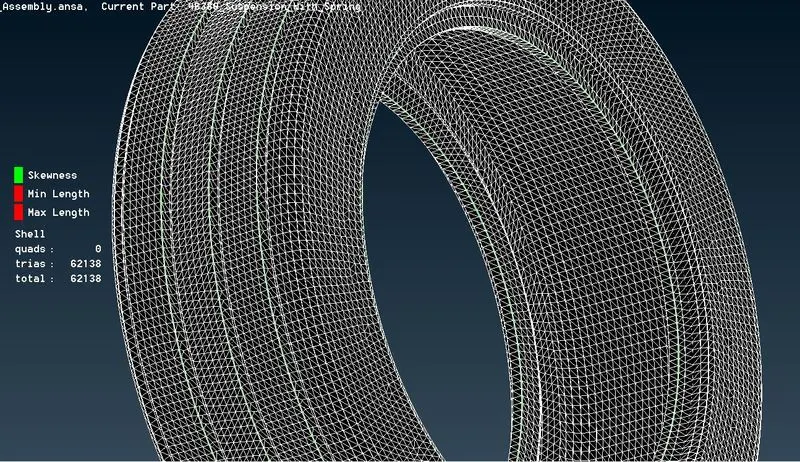
Fig. 4.1 After mesh on Tyre
- Perform the same operation and the quality criteria for the Rim
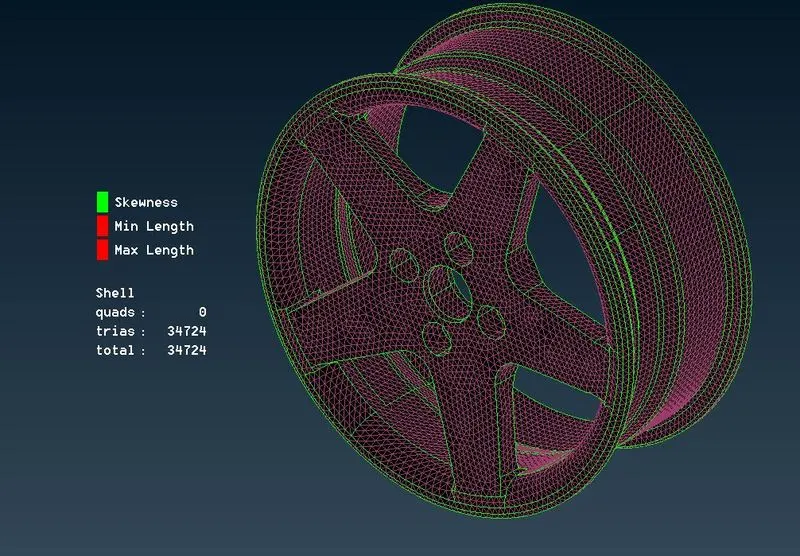
Fig. 4.2 After mesh on Rim
👉 Surface Mesh for Other structural components:
- In other components, We can go with Manual mesh, Because there are lots of curvy surfaces are there so Manual is best instead of Batch.
-
To use Spot mesh - [ Mesh module > Mesh Generation > Spot ]
-
Spot mesh is a manual mesh method that takes more hours but it's a very safe method because while doing with batch mesh we are unable to check every single area while the mesh is good or not.
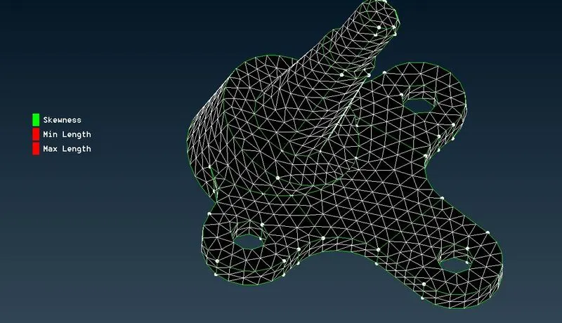
Fig. 5.0 After meshing on Rim
👉 For structural Assembly:
- For this method, If the thickness is less than 5mm then we use the Mid-surfacing method.
- Create the Mid surface of the Components.
- Perform the mesh on the Mid-surface
- Mid – Surface extraction is the method to simplify the meshing operation. If we didn’t use the mid surface then the simple geometry of the meshing process can take a very long time to achieve the proper result.
- NOTE:- Please untick the option[Delete Original Faces]
- Mid-surface extraction is creating a shell in the middle of the outer and inner surface of a solid model or geometry. It converts the solid geometry into a thin shell, which reduces the time taken for meshing by reducing the areas to mesh.
- Assign the offset value of the shell, before assigning check the thickness value of the sheet metal.
They are some methods to mid-surface the elements such as,
- Face Offset method
- Face Middle method
- Skin method
In this project, I go with the Face Offset method,
Face offset method👇:
[ Face module > Offset > face ]
Before offset the face, please measure the thickness value. After selecting one side of the face, input the value as the direction of the arrow.
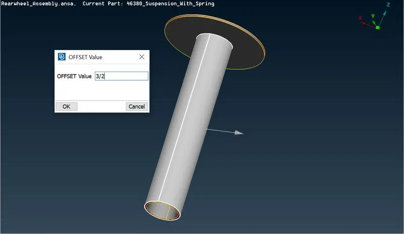
Fig. 6.0 During Offset
- Input the Offset value as half of the Thickness.
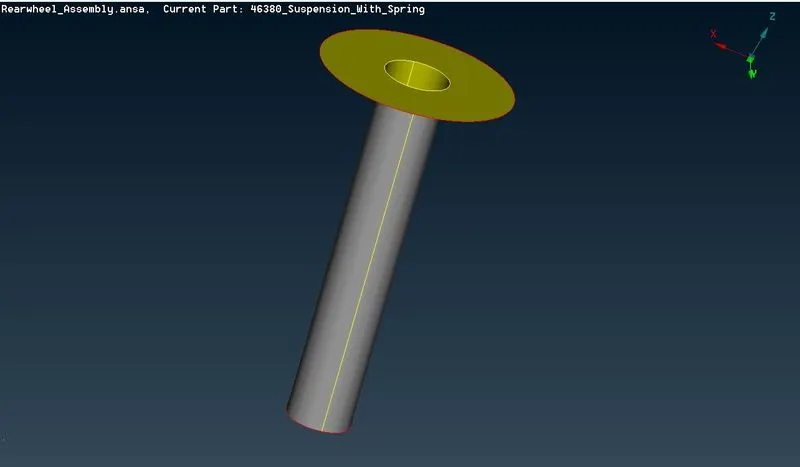
Fig. 6.1 After Offset
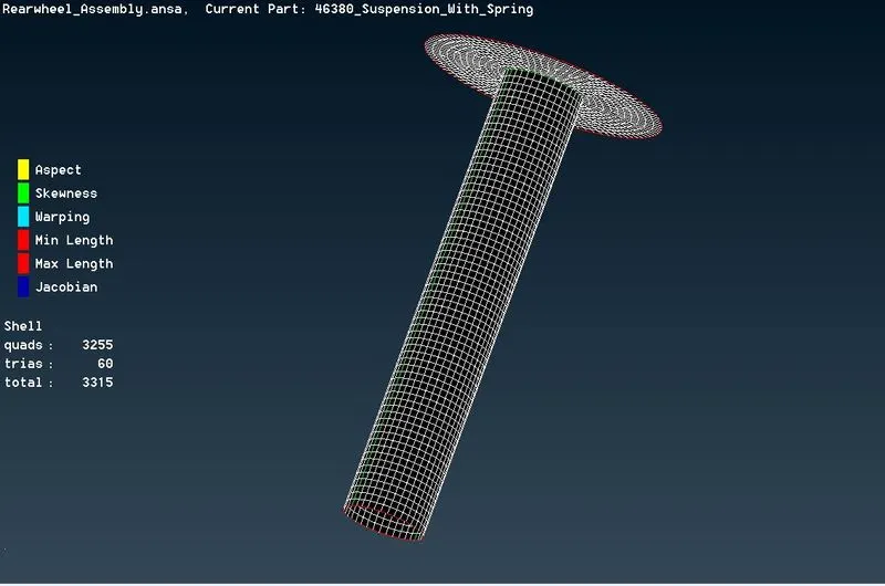
Spot Mesh method👇:
To use Spot mesh - [ Mesh module > Mesh Generation > Spot ]
Spot mesh is a manual mesh method that takes more hours but it's a very safe method because while doing with batch mesh we are unable to check every single area while the mesh is good or not.
Connections:
The joining of two or more elements by mechanical fasteners such as bolts, rivets, or welds called Connection. There are different types of Joint are made in the CCB part are,
- Bolted joint
- Riveted Joint
- Welded joint
To perform the joint in ANSA, we use several types of connection for the simulation purposes are
- RBE2 Method
- Seam Weld
- Spot weld
- Bolt connection
By RBE2 Method:
- Go to the Nastran deck for creating the RBE2(Rigid body element 2) [ Nastran deck > Element > RBE2 > Many nodes ]
- Select the nodes by using loop selection.
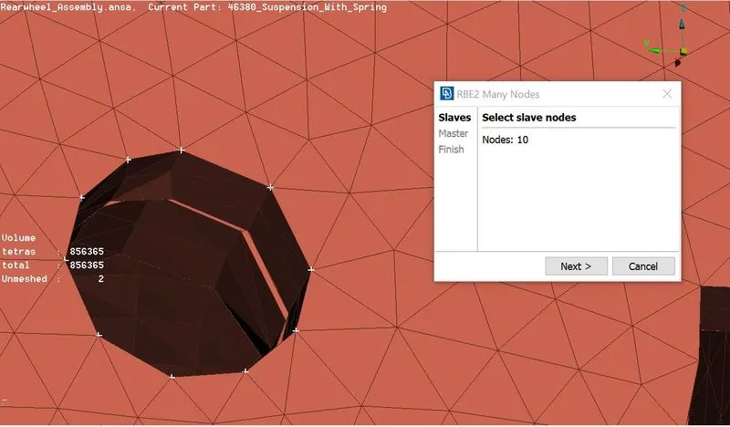
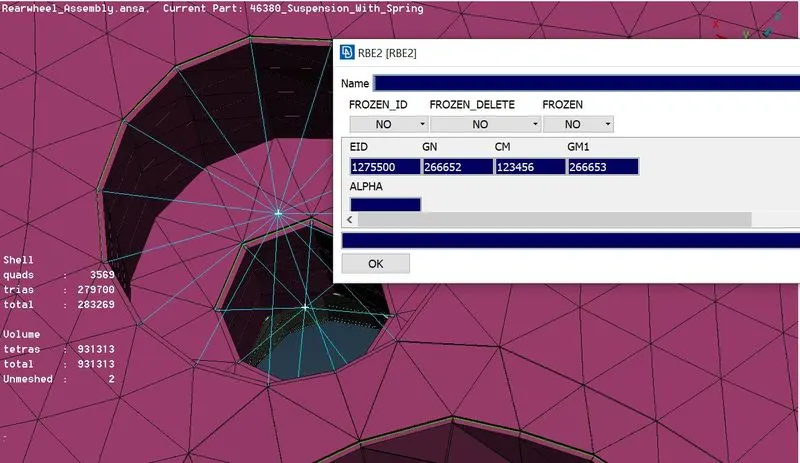
- CM - Degree of freedom, GN - Master node, EID - Slave node.
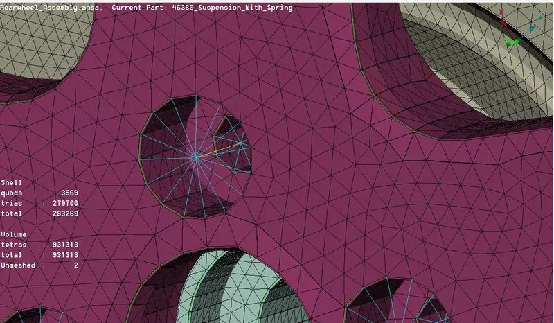
- After creating both slots for the bolt, By using the RBE2 - Two nodes method create the stem of the bolt.
Assign Symmetry:
- The Symmetry is done to make half of the rear suspension as the complete model. To complete the model follow the steps,
- In Utilities Tab >> Select Transform >> Copy >> Select the Entities >> Select Symmetry tab >> Select Mirror 3 point plane >> Select 3 points which create a plane to get a proper symmetry >> Click Ok >> Click Finish.
Conclusion:
The Given Rear suspension has been completed with the Good mesh with Volume and connections.
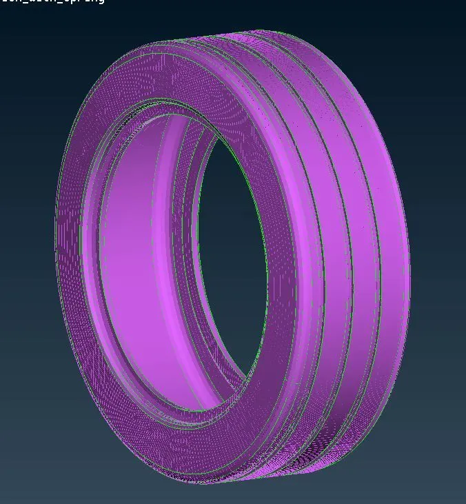
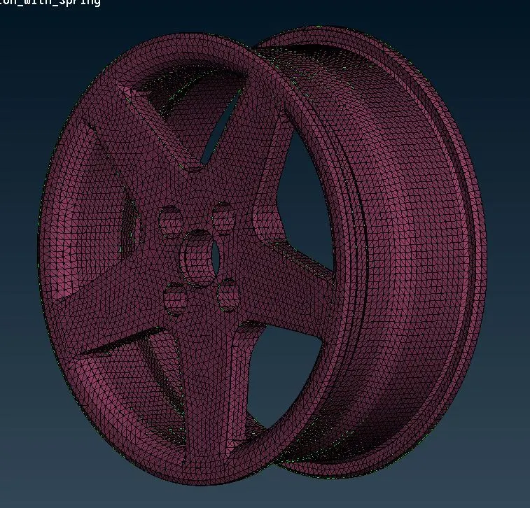
Fig(a) - Tyre Fig(b) - Rim
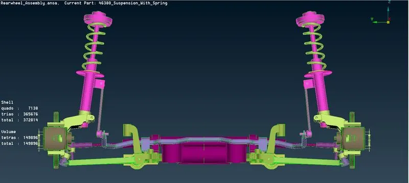
Fig(c) - Structural Part
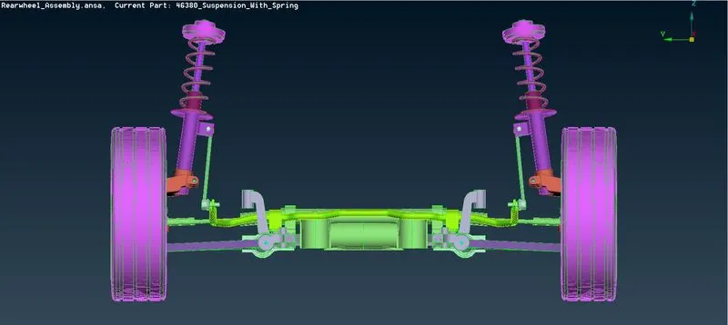
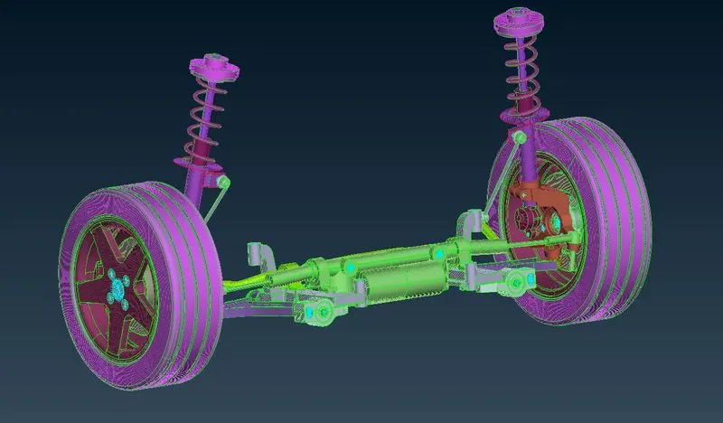
Fig (d) - Entire Rear suspension Assembly
Learning Outcome:
- This project will improve the confidence of how to do volume meshing and connection in a bulk object like this.
- Revise the entire stages in Preprocessing.
- Improves the working speed.
Google Drive Link:
https://drive.google.com/file/d/1B9VlGwSTJUKa-eb46SoZLXXp-3-67-nh/view?usp=sharing