Project 2
Aim:
To model and design a proposed Pre Engineered Building Warehouse (Rigid frame structure) using STAAD.Pro with the following technical specifications.
Procedure:
- Plan view, elevation views of the Pre Engineered Building are as shown below.
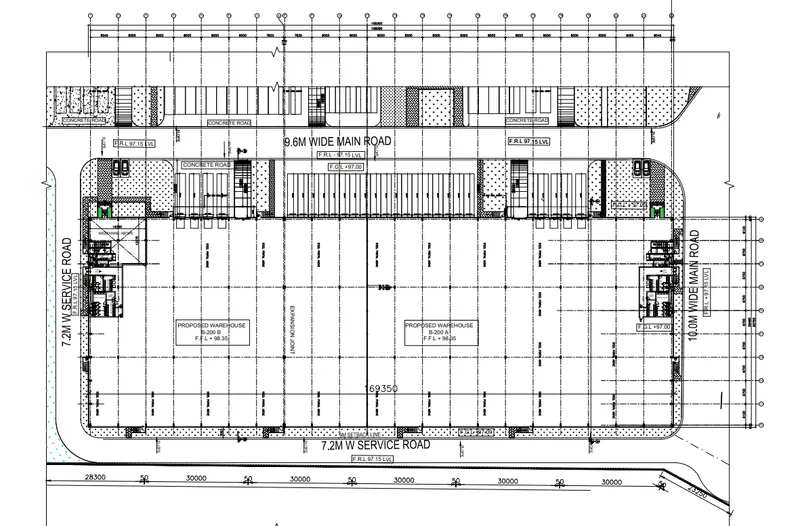
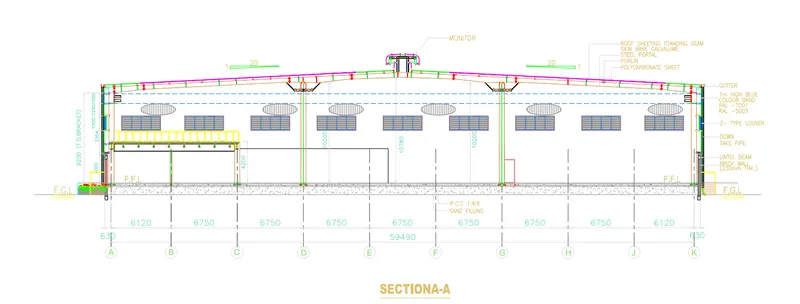
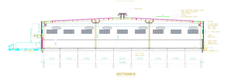
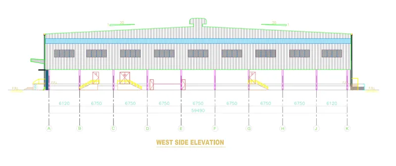
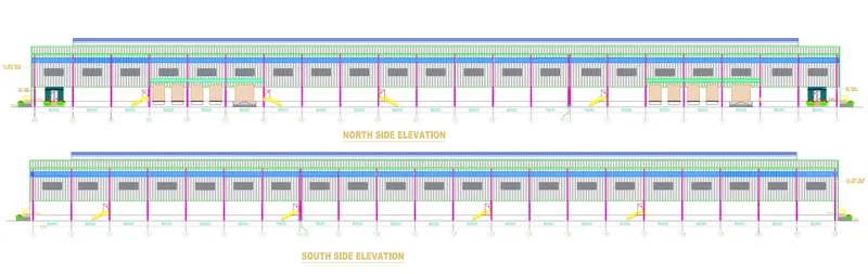
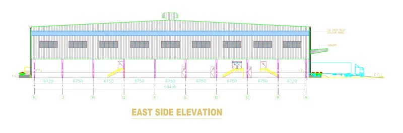
- We have to model the PEB frame in STAAD.PRO as per the above given drawings.
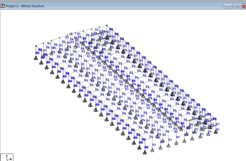
- The modelled PEB frame in STAAD.PRO will appear as shown in the below figure.
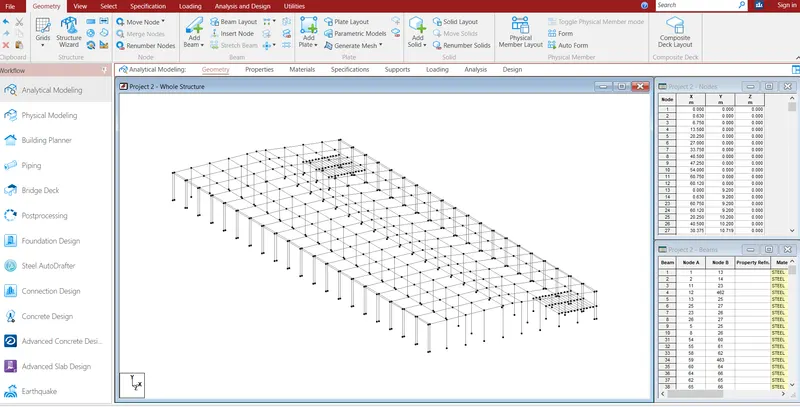
- Supports are added to the columns as needed.
- Releases and specifications are also applied wherever necessary in the modelled frame.
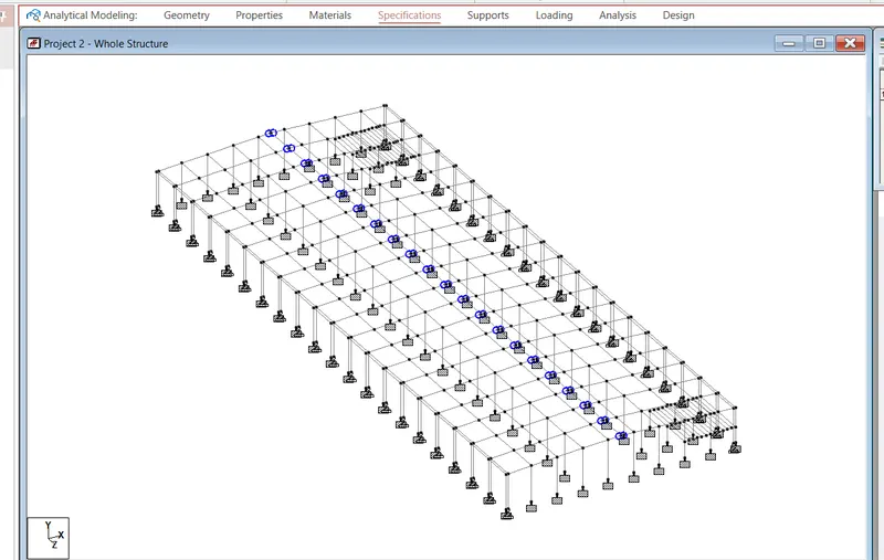
- All the section properties and materials are also applied to all the members respectively as mentioned in the question.
-
Calculation of Design Loads on PEB warehouse :-
- Dead Load
- Dead Load on Rafter
- Weight of Roof Sheet = 5 Kg/m2
- Weight of Purlin and sag rods = 5 Kg/m2
- Additional weight = 5 Kg/m2
Total weight of rafter = 15 Kg/m2
Dead load on rafter = 15 x 10 x 8 = 1200 N/m = 1.2 kN/m
- Dead Load on Purlin = 10 x 10 x 8 = 800 N/m = 0.8 kN/m
- Mezz slab self-weight (150 mm thick slab) = 0.15 x 25 kN/m3 = 3.75 kN/m2
- Floor finishes and additional load on Mezzaline floor = (150 + 500) kg/m2 = 0.65 kN/m2
- Weight of 230mm thick brick wall (4-m height) on Mezzaline floor = 20 kN/m3 x 0.23 x 4 = 18.4 kN/m
- Live Load
- Live Load on roof and canopy = 57 kg/m2 x 10 x 8 = 4.56 kN/m
- Live Load on Mezzaline floor = 400 kg/m2 = 4 kN/m2
- Collateral Load
- Collateral Load on Roof
- Load of electrical fittings = 0.1 kN/m2
- Load of sprinklers = 0.03 kN/m2
- Load of rockwool insulation and bubble wrap insulation = 0.15 kN/m2
- Load of solar panels = 0.15 kN/m2
- Load of ceiling = 0.1 kN/m2
Total Collateral load on Roof = 0.53 x 8 = 4.24 kN/m
- Collateral Load on Mezzaline floor (due to false ceiling and electrical fittings)
= 0.2 x 8 = 1.6 kN/m
- Collateral Load on column due to bracket beam
Load due to service line supported on the beam spanning 8 m width= 150 kg/m x 8 x 10 = 12 kN
Moment acting on column due to service line = 12 x 0.75 = 9 kNm
- Collateral Load on jack beam due to service line= 2.5 kN/m
- Collateral Load on Mezzaline false ceiling = 3.2 kN/m
- Wind Load
Basic wind speed = 39 m/s
K1 - 1.00
K2 - 1.05 (Terrain Catogory-1. Building height at eaves = 10.50 m)
K3 - 1.00
K4 - 1.00 (For other structures)
Kd -0.9
Ka (Rafter) - 0.8 or as per tributary area.
Ka (Column) - 0.8245 or as per tributary area.
Ka (Purlin) - 0.9721 or as per tributary area.
Ka (Side Runner) - 0.978 or as per tributary area
Kc -0.9
Design wind pressure = pd = kd x ka x kc x 0.6 x (Vb x k1 x k2 x k3 x k4)2 = 0.652 kN/m2
But should not be less than 0.7 Pz = 0.7 x 1.006 = 0.704 kN/m2
Cpe - As per table 5 & 6 of IS: 875 (Part 3) – 2015
h/w = 10/60 = 0.6
L/w = 170/60 = 2.83
Cpe On wall:
Direction
A
B
C
D
0 deg.
0.7
-0.25
-0.6
-0.6
90 deg.
-0.5
-0.5
0.7
-0.1
Cpe On Roof:
Roof angle = 2.86
Direction
EF
GH
EG
FH
0 deg.
-0.86
-0.4
90 deg.
-0.8
-0.4
Cpi = 0.2
Wind Load on Columns = (Cpe – Cpi) x A x Pd
Wind about X Direction + Cpi on Wall A = (0.7 – 0.2) x 8 x 0.704 = 2.816 kN/m
Wind about X Direction + Cpi on Wall B = (-0.25 – 0.2) x 8 x 0.704 = -2.534 kN/m
Wind about X Direction + Cpi on Wall C & D = (-0.6 – 0.2) x 6.75 x 0.704 = -3.802 kN/m
Wind about X Direction - Cpi on Wall A = (0.7 + 0.2) x 8 x 0.704 = 5.069 kN/m
Wind about X Direction - Cpi on Wall B = (-0.25 + 0.2) x 8 x 0.704 = -0.282 kN/m
Wind about X Direction - Cpi on Wall C & D = (-0.6 + 0.2) x 6.75 x 0.704 = -1.9 kN/m
Wind about Z Direction + Cpi on Wall A = (-0.5 – 0.2) x 8 x 0.704 = -3.942 kN/m
Wind about Z Direction + Cpi on Wall B = (-0.5 – 0.2) x 8 x 0.704 = -3.942 kN/m
Wind about Z Direction + Cpi on Wall C = (0.7 – 0.2) x 6.75 x 0.704 = 2.376 kN/m
Wind about Z Direction + Cpi on Wall D = (-0.1 – 0.2) x 6.75 x 0.704 = -1.425 kN/m
Wind about Z Direction - Cpi on Wall A = (-0.5 + 0.2) x 8 x 0.704 = -1.689 kN/m
Wind about Z Direction - Cpi on Wall B = (-0.5 + 0.2) x 8 x 0.704 = -1.689 kN/m
Wind about Z Direction - Cpi on Wall C = (0.7 + 0.2) x 6.75 x 0.704 = 4.276 kN/m
Wind about Z Direction - Cpi on Wall D = (-0.1 + 0.2) x 6.75 x 0.704 = 0.475 kN/m
Wind Load on Rafters = (Cpe – Cpi) x A x Pd
Wind about X Direction + Cpi = (-0.86 – 0.2) x 8 x 0.704 = -5.970 kN/m on Side A Rafter
Wind about X Direction + Cpi = (-0.4 – 0.2) x 8 x 0.704 = -3.378 kN/m on Side B Rafter
Wind about X Direction - Cpi = (-0.86 + 0.2) x 8 x 0.704 = -3.716 kN/m on Side A Rafter
Wind about X Direction - Cpi = (-0.4 + 0.2) x 8 x 0.704 = -1.125 kN/m on Side B Rafter
Wind about Z Direction + Cpi = (-0.8 - 0.2) x 6.75 x 0.704 = -4.752 kN/m Side C Rafter
Wind about Z Direction + Cpi = (-0.4 - 0.2) x 6.75 x 0.704 = -2.851 kN/m Side D Rafter
Wind about Z Direction - Cpi = (-0.8 + 0.2) x 6.75 x 0.704 = - 2.851kN/m Side C Rafter
Wind about Z Direction - Cpi = (-0.4 + 0.2) x 6.75 x 0.704 = -0.950 kN/m Side D Rafter
Wind Load on Canopy :
Cp - As per table 8 of IS: 875 (Part 3) – 2015
Roof Angle 2.86 deg.
Cp -ve = 1.08
Cp +ve = 0.35
Wind Load on Canopy (Upward) = 1.08 x 8 x 0.704 = 6.082 kN/m
Wind Load on Canopy (Downward) = 0.35 x 8 x 0.704 = 1.971 kN/m
- Seismic Load :
-
As per IS: 1893 - 2016
Seismic zone - III - Z = 0.16
Rf - 4.0
I - 1.0
SS - 3.0
25% of Live Load on roof is considered for calculation of seismic forces.
100% of collateral load on roof is considered for calculation of seismic forces.
50% of (Live load + Collateral load) on mezzanine floor is considered for calculation of seismic forces.
100% of Dead load is considered for calculation of seismic forces.
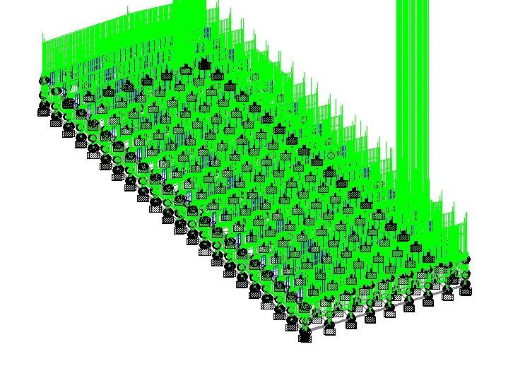
- Loading has been applied on the model.
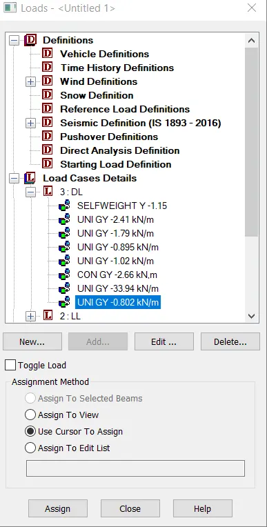
- Load on the modelled structure can be seen as shown below in the figures.
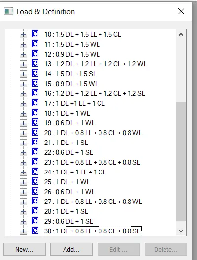
- All the load combinations are applied on the model wherever necessary.
Design Parameters:
- IS 800 LSD
- FYLD = 345000 for portal frame and mezz beams
- FYLD = 250000 for bracings
- Beam = -1
- STP = 2 for welded sections
- Main = 250 for tie beam
- Ly = Lx = 1.5m for rafter
- Ly = Lx = 3.25m for columns
- Ly = Lx = 4.4m for columns supporting canopy
- Lz = 11m for internal columns
- Ly = Lx = 0.5m for mezz floor beams
- Lz = 6.75m for mezz floor beams
- Ly = 1.7m for canopy beam
- Ratio = 1
Now, the above design parameters have to be applied on the PEB structure.
- Run the analysis on the PEB structure and check for errors.
- Stop any more modelling only after we see no errors after doing the analysis of the PEB warehouse.
Result:
PEB Warehouse has been succesfully modelled and designed with the needed load cases and the specifications. Also analysis has been performed with no errors.