Meshing of Wheel Assembly using ANSA
- INTRODUCTION
A vehicle, after being completely manufactured and ready to run on the road, is tested, before launching into the market, to check its performance, safety, and durability. The number of sensors and transducers are connected to it, to collect the real-time data. However, a vehicle cannot be kept running for thousands of kilometers to collect the data. The availability of such a driver is another problem. Because vehicle testing in the real environment can be performed up to a certain limit, often a quarter car is tested in the experiments of durability, fatigue, or NVH.
The quarter car model is only a wheel assembly of any side of the car. Sometimes extra attachment might be attached to it if it is a part of the concern. In experiments, it is the sensor and the transducer which is responsible to collect the data, and therefore, they need to be highly calibrated. In a finite element analysis, the same model is modeled and tested to check the accuracy of the result. If the result that occurs gave a result close to the true value, then the model can be tested in any environment for the time as desired. In this work, rear-wheel assembly is taken as the model to pre-process for finite element analysis. The model consists of the tire, the rim, the knuckle, suspension assembly, steering assembly, and some frame parts. Using ANSA, the assembly has been discretized using the shell as well as solid elements, and then respective connection elements are also given to each connected parts.
Aim
To discretize the rear wheel assembly, and deploy the required connections between every connected part.
Objective
- To discretize the assembly using the shell as well as solid elements, as required.
- To deploy connections, wherever required.
- PROCEDURE
The rear-wheel assembly when imported into ANSA, it was not having many distortions. The model was quite clear to understand. Even though it was clear to understand, it had to be made free from errors to pre-process on it. Therefore, using the geometrical check manager, the geometry was checked for the presence of any errors. In just a few seconds, some 6 errors were detected which were belonging to single con errors and the cracks between cons, as shown in fig. 1. The errors were eliminated manually and then the model was observed for any discrepancies present in it.
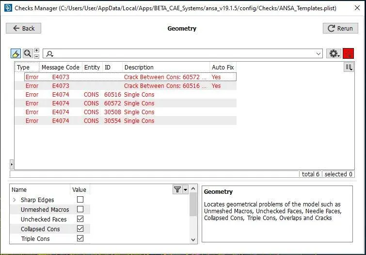
Figure 1: Detection of 6 errors in the geometry, using geometrical check manager.
When the model was completely free from any kind of geometrical errors, it was then ready to take for further procedures. The model of the rear-wheel assembly had all of its parts in a single PID (property ID), except the rim and the tire, as shown in fig. 2. There were almost 21 different parts and each had to be kept under a different PID, to independently work on it. Therefore, it was the manual work to put each different part in a different PID. Fig. 3 shows the model, in which each part was kept in a different PID.
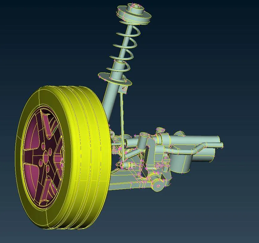
Figure 2: The model of the rear-wheel assembly with all of its parts in a single PID (Property ID), except the rim and the tire.
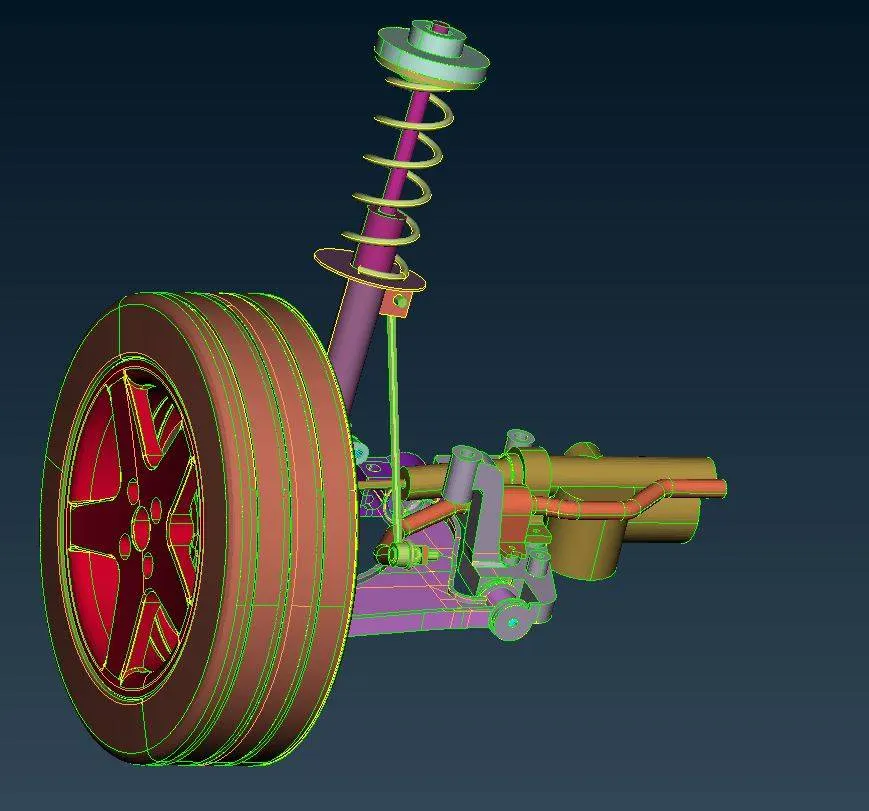
Figure 3: The model of the rear-wheel assembly with all of its parts in different PIDs.
Setting Quality Criteria
A mesh element has to be of good quality to get close results. The quality set for the elements depends on the desired accuracy. To check the quality of the element various parameters have been set viz. aspect ratio, warpage, skewness, the minimum, and maximum length. Failure of the element would lead to divergence of the solution from the true value. In this work, four sets of qualities were provided as shown in the table below.
Table 1: Quality criteria for tria elements (tire and rim).
| Target/Average length | 6.5 |
| Minimum length | 5 |
| Maximum length | 10 |
| Skewness | 45 |
Table 2: Quality criteria for mixed elements (for mid-surface only).
| Target/Average length | 4 |
| Minimum length | 2 |
| Maximum length | 6 |
| Aspect | 3 |
| Warpage | 15 |
| Skewness | 45 |
| Jacobian | 0.7 |
| Minimum Quad Angle | 45 |
| Maximum Quad Angle | 135 |
| Minimum Tria Angle | 30 |
| Maximum Tria Angle | 120 |
Table 3: Quality criteria for tria (for other components):
| Target/Average length | 4 |
| Minimum length | 2 |
| Maximum length | 6 |
| Skewness | 45 |
Table 4: Common quality criteria for tetra elements:
| Tet-collapse | 0.2 |
Discretization or Meshing with Solid Elements
When the model is free from errors and the quality is set for the elements, the model could now be taken to mesh. When the model is hollow from the inside, it means it does not have any specific thickness. Also, a model that has indefinite shapes, such models are discretized with solid elements. To create solid elements, macros or shell elements are created on the surface of the model, and they are then converted to Tetra- or Hexa-elements, from the inner side.
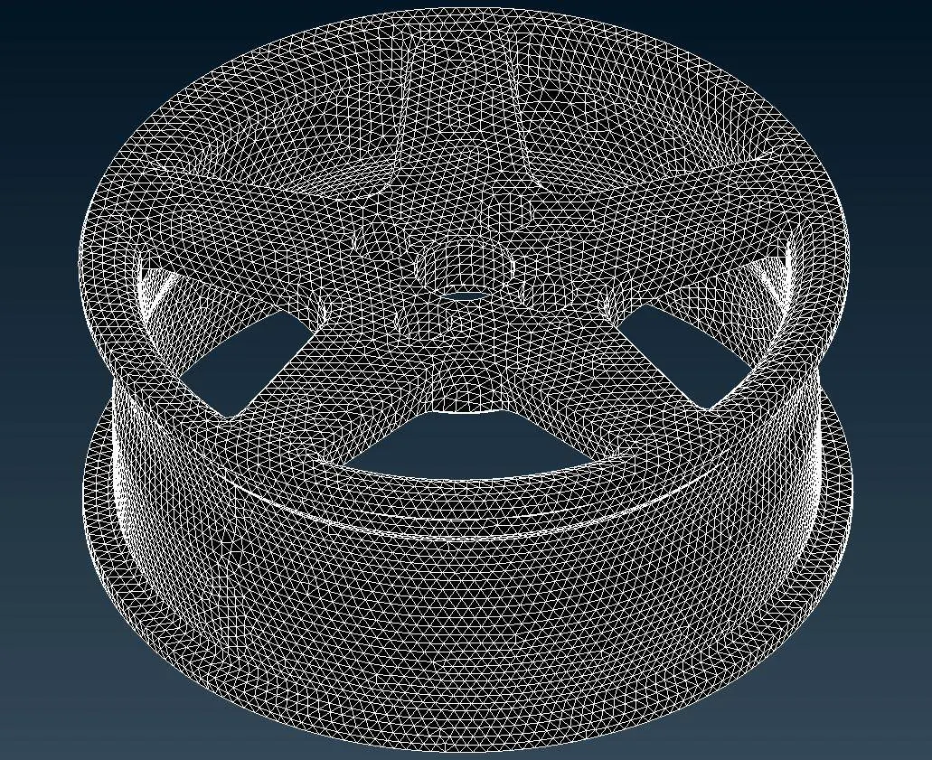
Figure 4: Shell meshing of the rim of a car with tria and ortho-tria elements.
Firstly, the rim and tire meshed. Considering the quality of the elements as shown in table 1, for rim and tire, those two parts were meshed with both tria and ortho tria shell elements. Ortho-tria elements are good in capturing the shape of the geometry as compared to tria, however, it takes longer computational time than tria elements. Therefore, compromisation is kept between tria and ortho-tria elements. Ortho-tria is used only where curves are present, and the remaining areas are meshed with tria-elements only, as can be seen in fig. 4.
Once the model meshes with shell elements, it has then to be converted to solid elements. Before doing that, the volume has to be defined, from the volume mesh deck, in the volume section. After it is defined, it registers in the list of meshed/unmeshed geometries, which can be checked from the ‘List’ option, as shown in fig. 5.
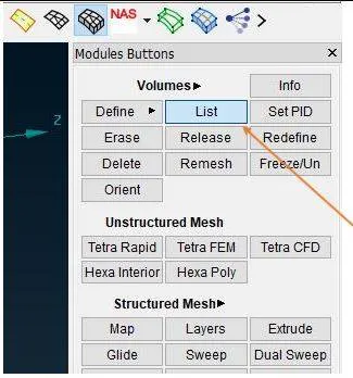
Figure 5: ‘List’ option in the volume section of the volume deck.
When it is clicked, a window pops out showing the list of meshed and unmeshed volumes, as shown in fig. 6.
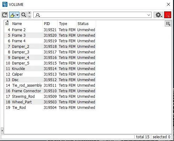
Figure 6: List of meshed/unmeshed volumes.
When any volume is right-clicked and the ‘remesh’ option is selected, it opens the options of elements by which the volume has to be meshed. In this work, ‘Tet FEM’ is used as the solid elements because it has a consistent growth rate for more number of layers, as compared to ‘Tet Rapid’ elements.
After meshing with solid elements, some off-elements might appear. Tet-collapse is the more common error of such elements. Whenever it appeared, it was corrected manually. Once the meshing is done, the meshed model has to be released from the CAD model, so that when one wants to export it, the CAD should not be attached to the meshed model. Similarly, other parts are meshed, wherever, the model has no thickness or is a closed volume.
Discretization or Meshing with Shell Elements
There were some parts in the rear-wheel assembly, which had definite thickness. Fig. 7 shows the parts of the suspension system which has thickness. In such cases, meshing is performed on the shell-surface.
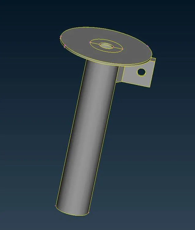
Figure 7: Part of the suspension system, having a definite thickness.
When the part has a definite thickness, mid-surface has to be generated, and keeping it in a separate PID, thickness has to be assigned to it. Using, ‘Middle’ option in the Topo deck and Faces section, mid-surface is generated as shown in fig. 8.
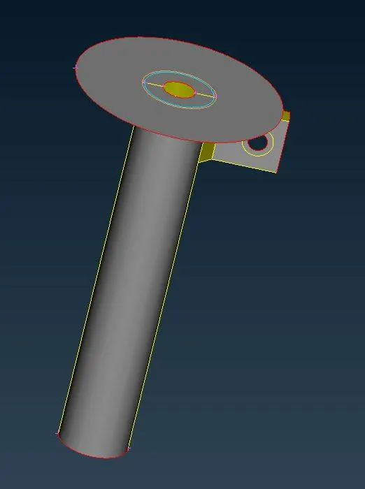
Figure 8: Mid-surface of the part of the suspension.
When the shell surface is created, meshing can be performed on that surface. Using quad and tria elements, these two parts were meshed, as shown in fig. 9.
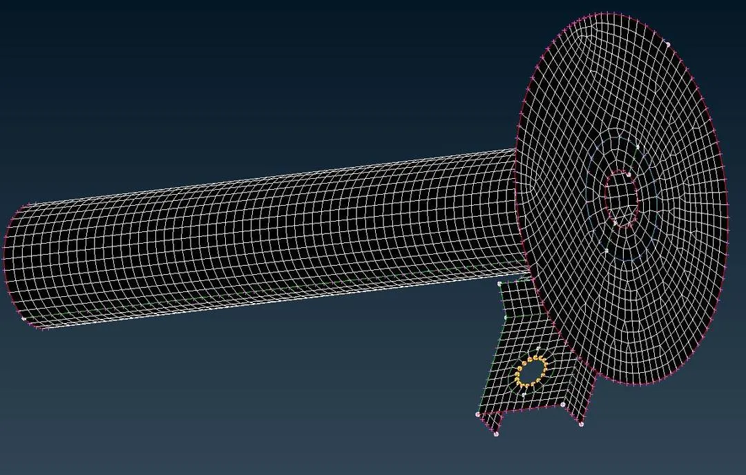
Figure 9: Meshed mid-surface of the part of the suspension.
Likewise, each part of the assembly meshed gradually. Fig. 10 shows the completely meshed rear-wheel assembly. When meshing manually, attention can be given to the selection of elements, which cannot be done using the automatic mesh method. Therefore, for doing the meshing manually, knowledge of elements is of utmost concern.
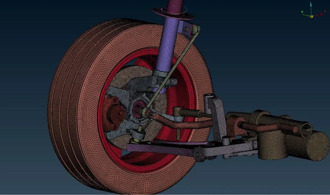
Figure 10: Meshed rear-wheel assembly.
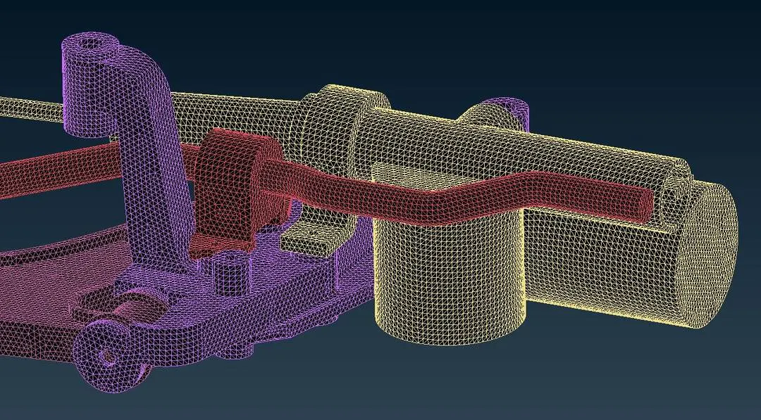
Figure 11: A closer view of meshing.
Connections
Part of pre-processing doesn’t complete if the assembly is not properly connected after meshing. An assembly might be connected with threaded joints, seam or spot weld joints, sometimes bushing might present. So such a connection has to be deployed to represent the assembly as the integrated one but not the separated one.
Bolted joints are generally represented using RBE2 or RBE3 elements. As shown in fig. 12, the yellow part is the mediator between the knuckle and the frame, and the pink part is the frame. Those two must be connected with a nut-and-bolt joint because the holes were matching. Therefore, to connect such parts, the RBE2 element was used. In the yellow marked circle, RBE2 elements can be seen in the blue color.
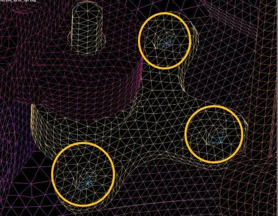
Figure 12: RBE2 elements deployed as a joint.
Such RBE2 elements can be generated when the hole is empty. In some cases, when there is a part in the hole, in such cases, RBE2 (two nodes) has to be selected, and each neighboring node has to be connected manually, as shown in fig. 13. In the figure, the bright yellow colored lines are the two nodes RBE2 elements.
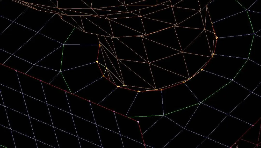
Figure 13: Two node RBE2 elements (in bright yellow color).
For seam welded joints, elements are created using the automatic method. For that to happen, a curve should be present to represent it as a seam weld line. In fig. 14, the purple color line is the curve that is generated using the ‘Feat2Curve’ option in the mesh deck and the section of the perimeters.
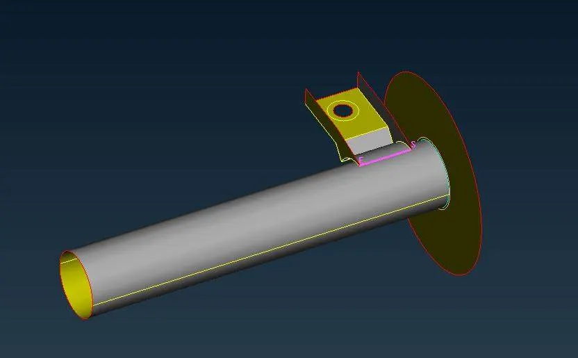
Figure 14: Curve (in purple color) representing the seam line weld.
When the connection manager is opened and the curve is selected, a window opens, in which some information has to be given, as shown in fig. 15. In the connection manager, P2 is selected as a pipe part, and P1 is selected as the other small part. ‘FE Rep Type’ is selected as the ‘overlap shell’. P2 is given as a base sheet, and the width is given 4. When the complete information is provided, and separate has been assigned for seam weld elements, and hit enter, a seam weld element realized as shown in fig. 16.
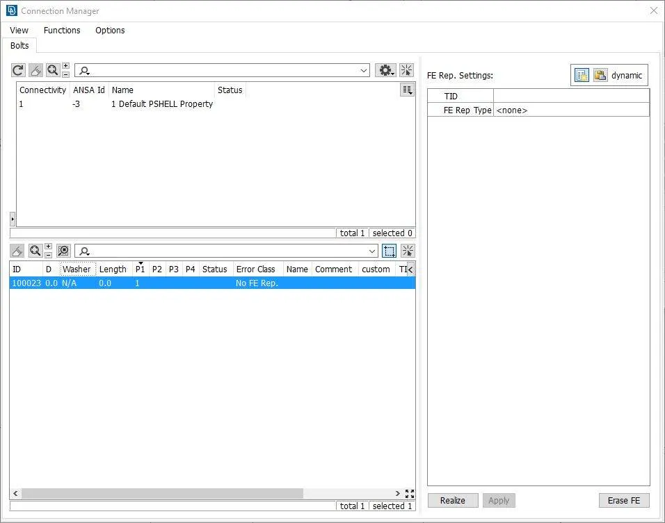
Figure 15: Connection manager.
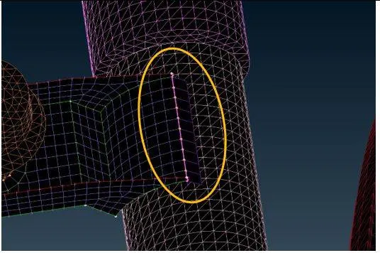
Figure 16: Seam weld elements (in a yellow marked circle).
- LEARNING OUTCOME
- When a part is present in the hole and it has to be connected, then two-node RBE2 elements are used.
- Node connectivity is mandatory when it is a single part. If the two parts are separate, node connectivity is not mandatory every time.
- The release option in the volume deck and the Nastran deck do the same thing – disconnect the CAD and FE.
- Two bodies under friction do not represent the joint.
- CONCLUSION
If any part is a closed volume, or if it is not having any definite thickness, it is meshed with solid elements, but if it has a definite thickness, it is meshed with shell elements. Part of pre-processing does not complete after just meshing. After meshing, the FE has to be released or disconnected from the CAD model. All the required connections have to be provided, using proper elements.