Project 2
AIM:
To create better shell and solid tetra mesh by applying given quality criteria parameters on the given Rear Suspension model with proper connections and assigning proper thickness to the model.
OBJECTIVE:
Make proper geometry cleanup before going to extract the midsurfaces of different components in the given model which are having thickness below 5mm. After that go for meshing by setting given quality criteria parameters and correct the failed elements, By using quality criteria tools then given the proper connections.Finaly assign the thickness to all the components in the given model.
GIVEN MODEL:
*Given Rear Suspension model is varying thickness along the component and it has different parts in the model is shown in below fig(1).
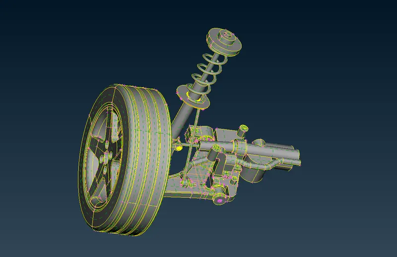
Rear Suspension model Fig(1).
*In Rear Suspension model it has different components i.e Tyre, Rim, spring, Suspension assembly etc. Manually identify the components which are below 5mm thickness, on those components perform shell mesh.
PROCEDURE:
i.GEOMETRY CLEANUP:
1.The Ansa software supports the generic CAD formats i.e( STEP,IGES,STL).
2.Import the cad geometry which is in any off above format in ansa by using open option by, selecting the File >> open.
3.Observe the geometry carefully and notice that geometry has any symmetrical faces, thriple cons, single cons etc.
4.To identify above mentioned geometric issues we have to use Checks option in that click on Geometry to open the Geometry checks manager tab as shown in below Fig(2).
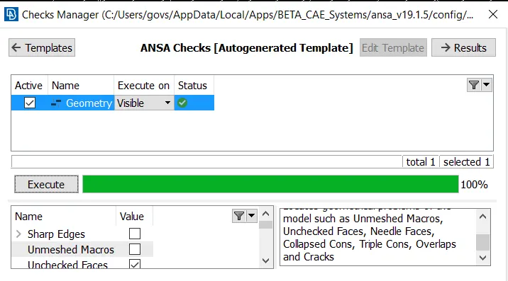
Geometry Manager Fig(2).
5.Above Fig(2) shows that the geometry does not have any geometrical errors. since it has executed upto 100 percentage.
6.Once geometry checks completed then extract the 'mid surface' either using mid-surface option or 'offset' option.
7.Mid-surface Skin option is used mostly in sheet metal operations because they have constant thickness throught the component.
8.Offset option used in both constant thickness and varying thickness components, but mostly used in plastic components due to varying thickness.
9.In this model by using 'offset' option to extract the mid-surface of component by, Selecting the TOPO >> Faces >> offet.
10.In Given Model the components which are below 5mm thickness are mesh with shell elements on their mid-surface.
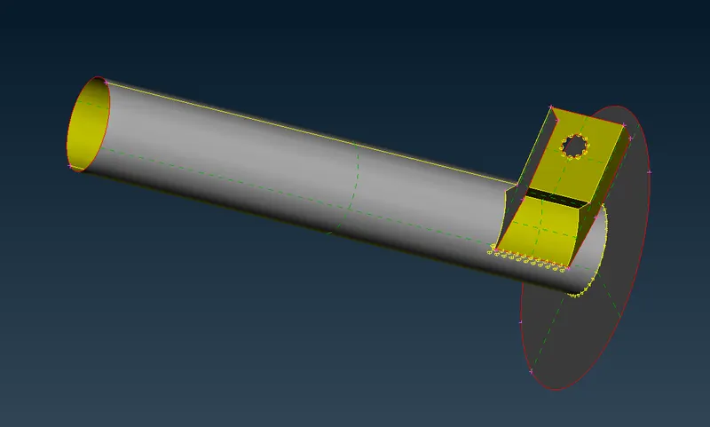
Mid-Surface of the components which are below 5mm thickness Fig(3).
11.After completing the geometry cleanup we can create the Quality criteria parametre file and mesh parametre file as shown in Fig(4) and Fig(5).
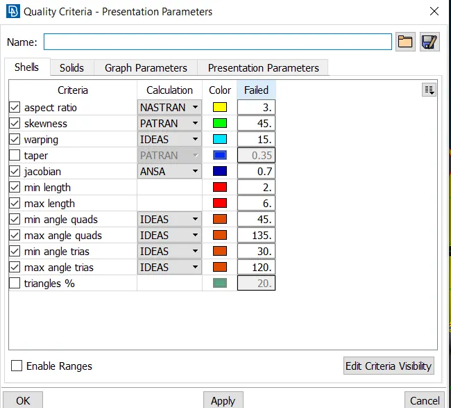
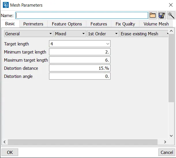
Quality criteria file Fig(4). Mesh parametre File Fig(5).
12.Before start the mesh assign the length value equal to average element length in parameters panel in TOPO module By, Selecting TOPO >> parameters >> length.
13.Perform the mesh using the Best or spotmesh options in Mesh Generation panel in MESH module by, Selecting the Mesh >> Mesh Generation >> Best or SPOT
14.Perform the mesh operations and eliminate the off element by using Reconstruct,smooth ,split and different options.
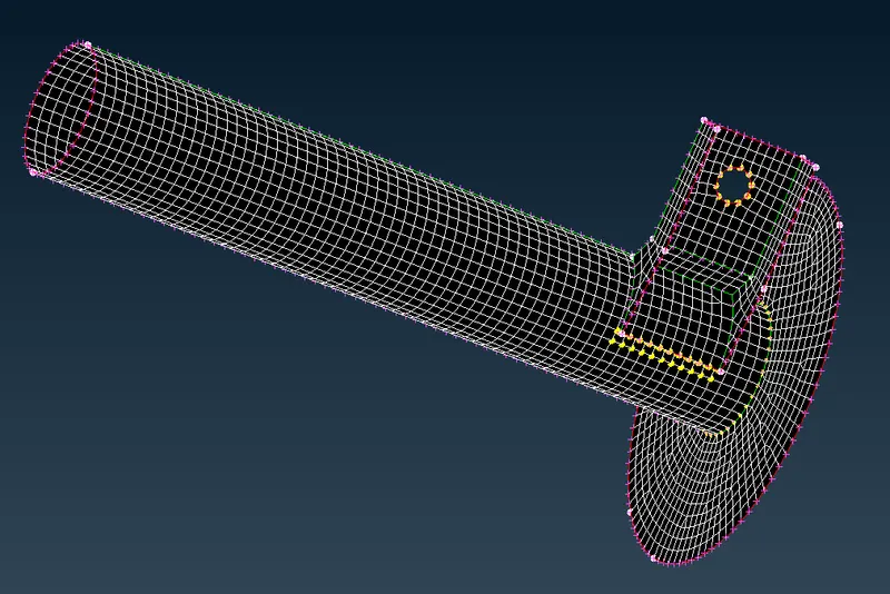
Shell Mesh with Mixed Type Fig(6).
15.Once after completing the mesh on the component make sure there are no off elements and unmeshed surface with proper feature capturing.
VOLUMETRIC MESH FOR TYRE AND RIM:
1.The Components which are above 5mm thickness are generally go with 3D meshing.
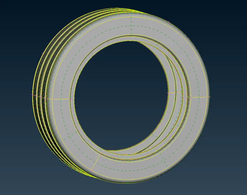
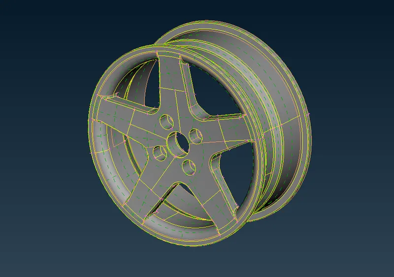
TYRE CAD MODEL Fig(7). RIM CAD MODEL Fig(8).
2.If we use tria Elements in the curved regions their is chance of surface distortion occuring.
3.So, It is better to use ortho tria elements in curved regions.
4.In flat regiongs it is better to go with tria elements because Computational time for ortho tria elements is more than tria elements.
5.Therefore in any tetra mesh proccess it is important to use both Trias and Otho Trias.
6.We have different Quality and mesh parameters for Tyre and Rim components is shown in below Fig(9) and Fig(10).
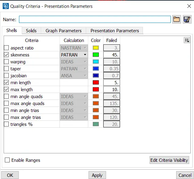
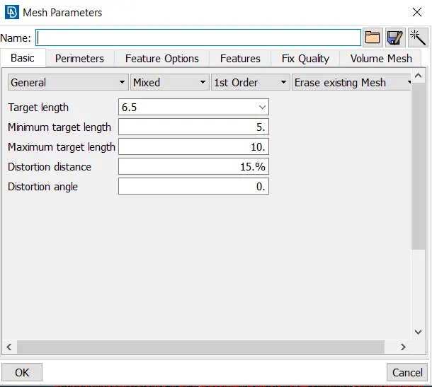
Quality Criteria File Fig(9). Mesh parameter File Fig(10).
7.Before start the mesh assign the length value equal to average element length in parameters panel in TOPO module By, Selecting TOPO >> parameters >> length.
8.Perform the mesh using the Best or spotmesh options in Mesh Generation panel in MESH module by, Selecting the Mesh >> Mesh Generation >> Best or SPOT
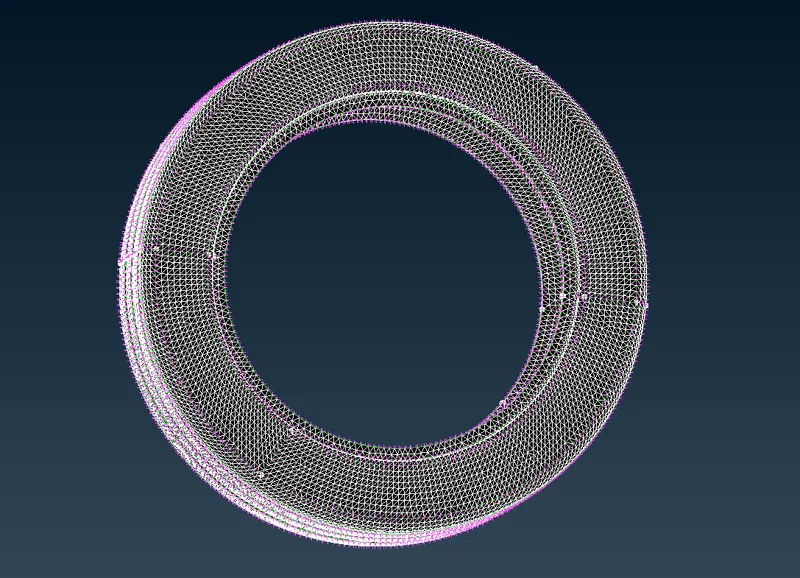
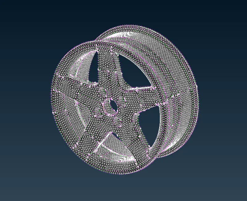
TYRE SHELL MESH Fig(11). RIM SHELL MESH Fig(12).
9.After meshing all surfaces with no minimum and mximum length errors, Create solid property to make Tetra mesh inside the surfaces By, Selecting the VOLUME MESH >> DEFINE >> MANUAL in VOLUME MESH menu.
10.After creating solid inside the surface perform the Tera Mesh by, Selecting the VOLUME MESH>Unstructured Mesh>Tetra Rapid function, of the Unstructured Mesh-Group, in VOLUME MESH menu.
11.For structural analysis we can use either Tetra Rapid or Tetra FEM.
12.Check for Tet collapse errors in 3D Tetra meshing, If any errors find remove them carefully without forming any kinks and raised edges on the surface.
13.Using Bounds option we can see the 3D Tetra mesh formation as shown in below Fig(11).
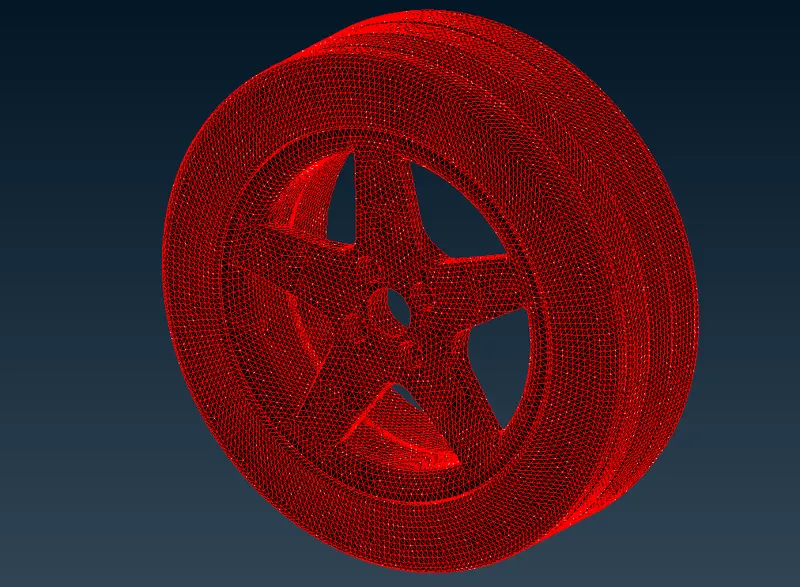
3D tetra Mesh of Both Tyre and Rim Fig(13).
REPRESENTING SPRING WITH 1D ELEMENT:
1.FEA Representation of torsional spring is different From normal procedure.
2.Generate the curve in the middle of the spring by, Selecting the TOPO >> CURVES >> MIDDLE.
3.Connect all different curves into single curve by, Selecting the TOPO >> CURVES >> CONNECT >> MULTI.
4.Create Centre of Gravity point for the curve to define the orientation of the curve by, Selecting the TOPO >> POINTS >> ON COG with Diameter 10mm.
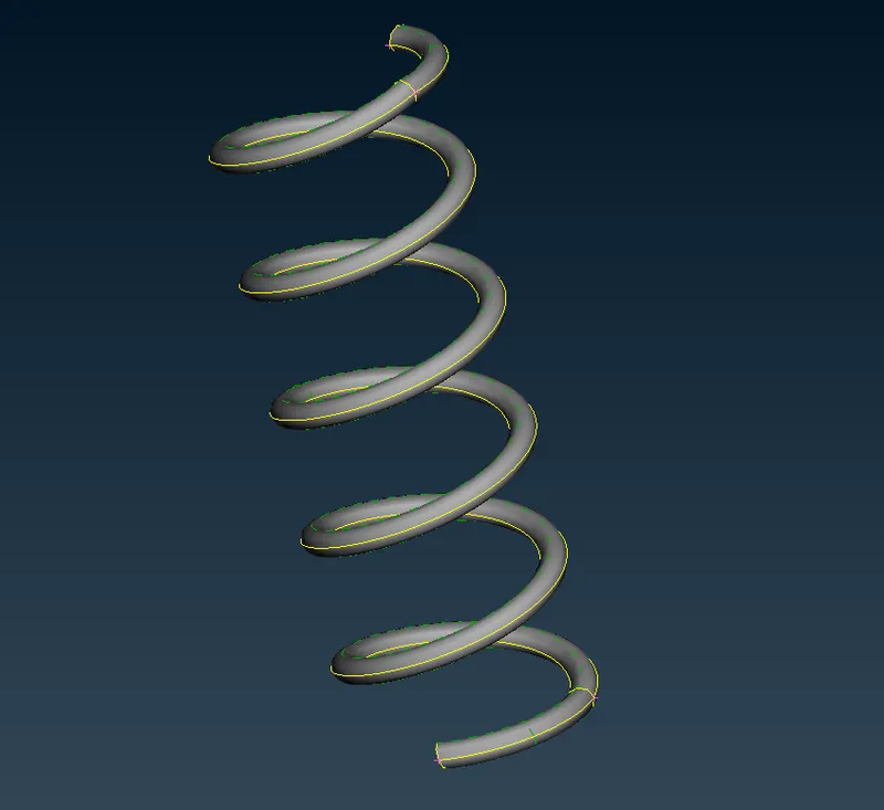
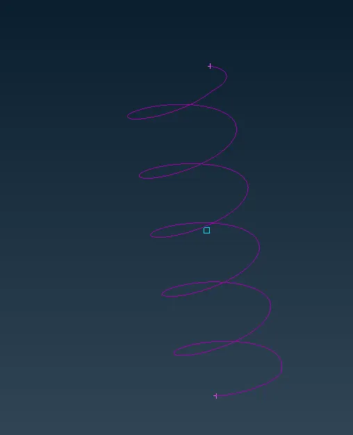
CAD MODEL OF PRING Fig(14). MIDDLE CURVE WITH COG POINT Fig(15).
5.In NASTRAN Module Represent this curve as 1-D CBAR element by, selecting NASTRAN >> ELEMENTS >> CBAR.
6.Enter element length which is equal to target element length i.e 4mm.
7.Create the property for the Bar element and define area by assign the cross sectional radius of the spring shown in below Fig(16).
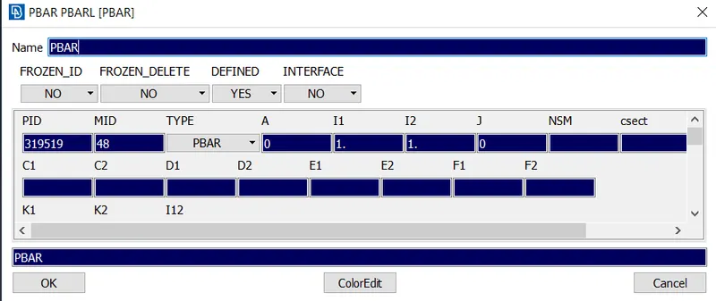
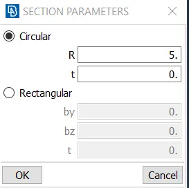
CBAR Property card Fig(16). Radius Fig(17).
8.After that to see the representation of 1D element as 3D solids check the box with 1D detailed representation as solids in quality parameters as shown in below Fig(18).
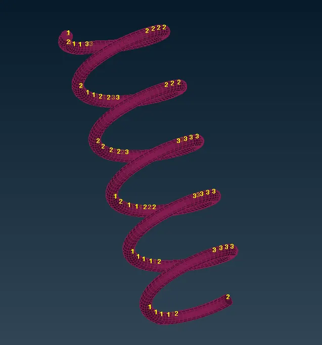
3D solid elements Fig(18).
RESULTS:
1.Shell and Solid meshing is done on the Rear suspension model with proper Connections ia show in below Figure(19).
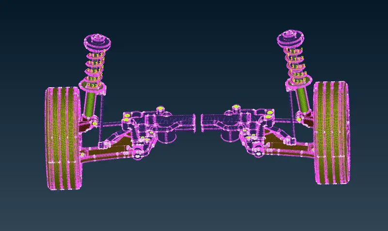
FEA Representation of Rear Suspension Model Fig(19).