Project 2
1.
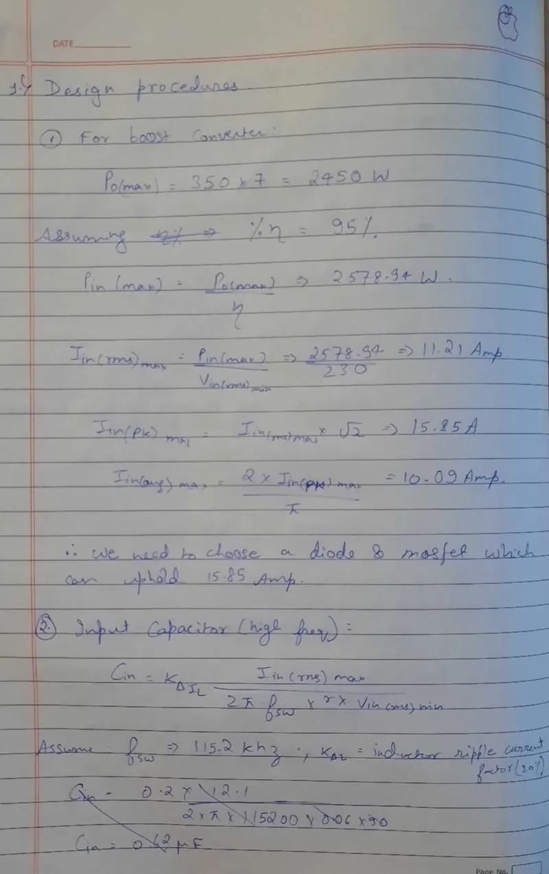
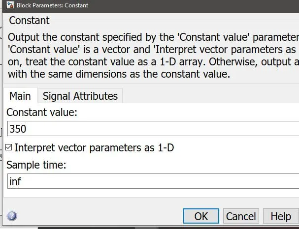
Vref:
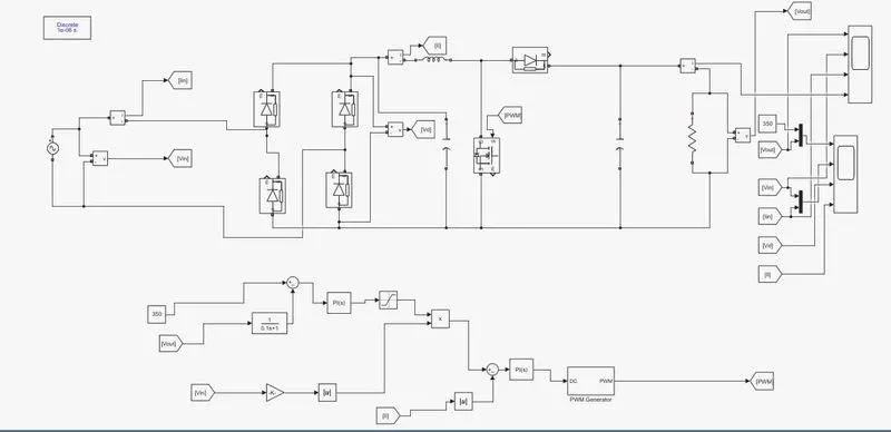
System:
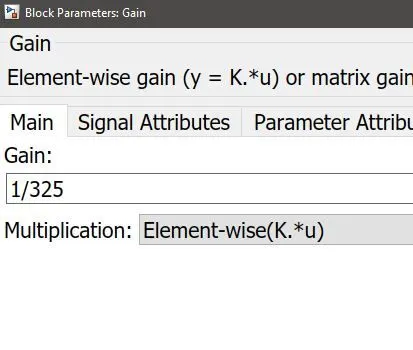
voltage loop gain:
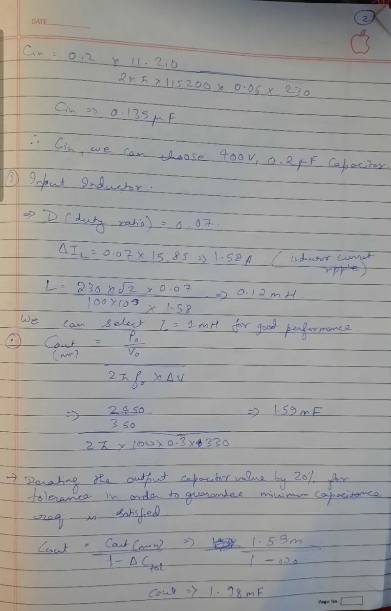
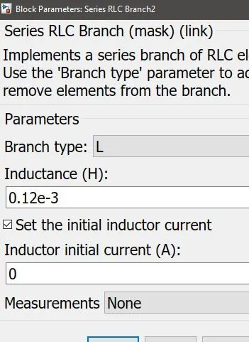
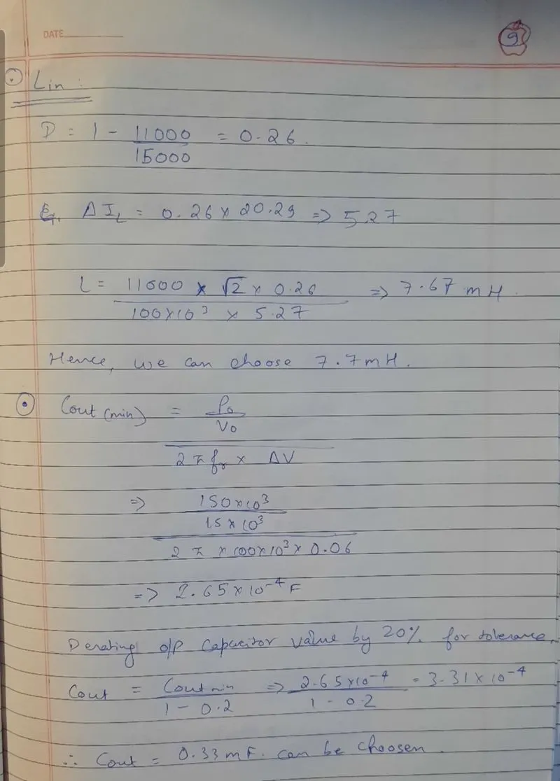
Lin;
Load:
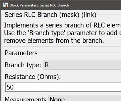
PID controller current loop:
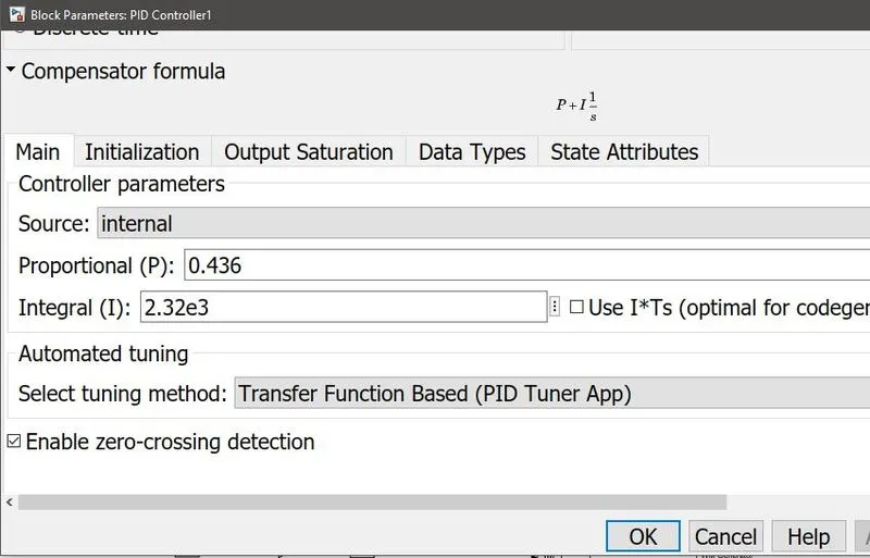
PID controller voltage loop:
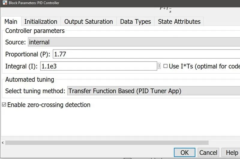
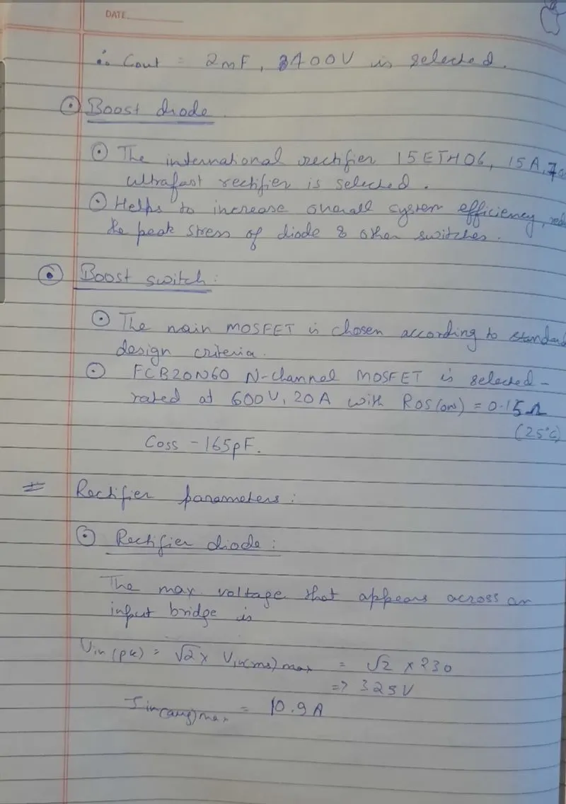
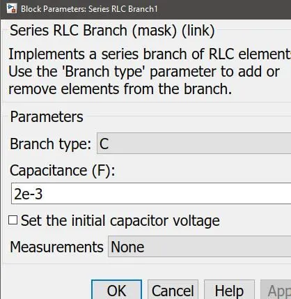
DC link capacitor:
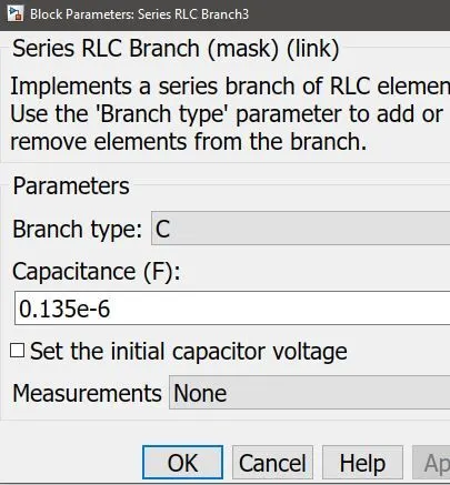
Cout:
output:
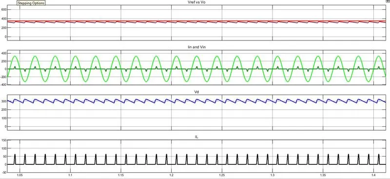
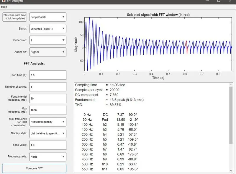
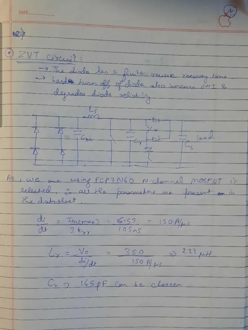
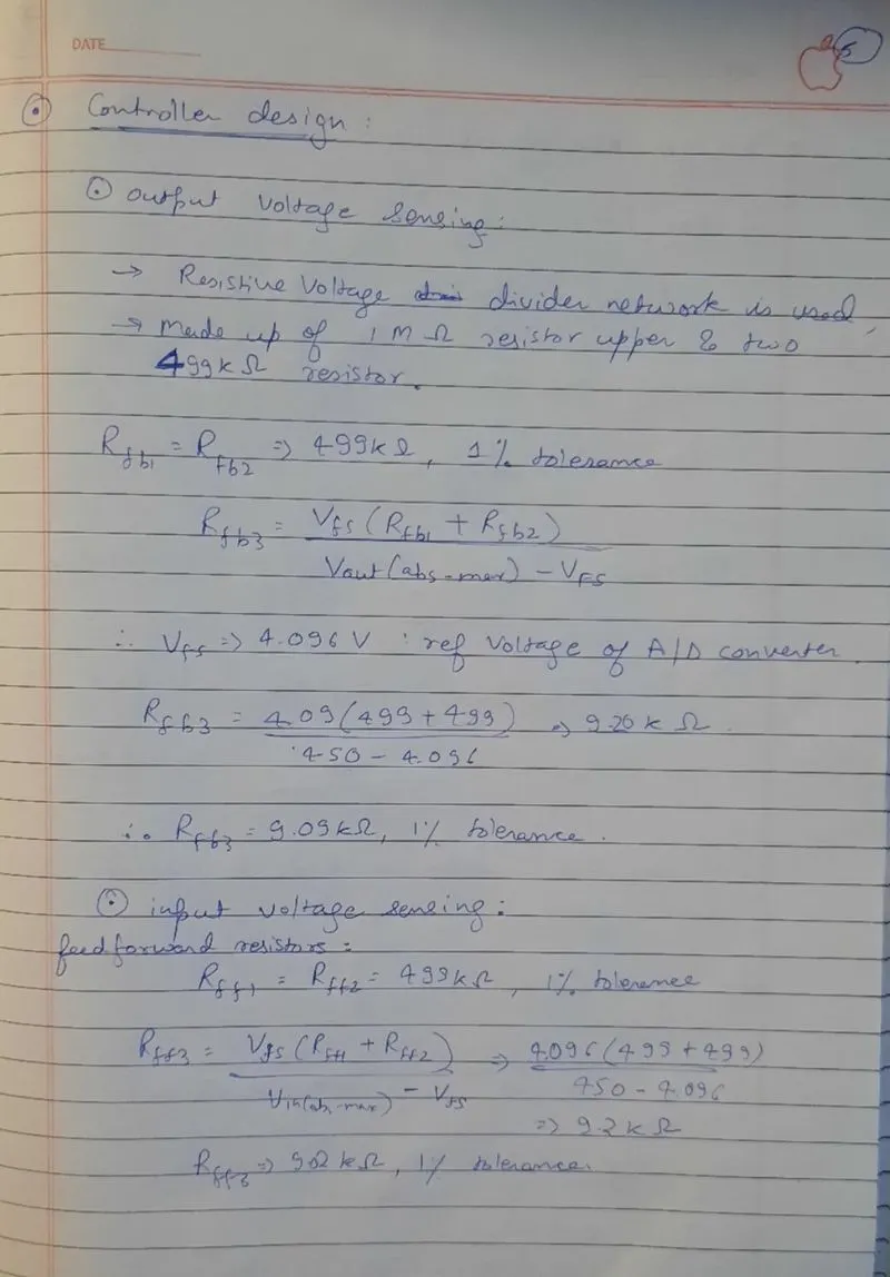
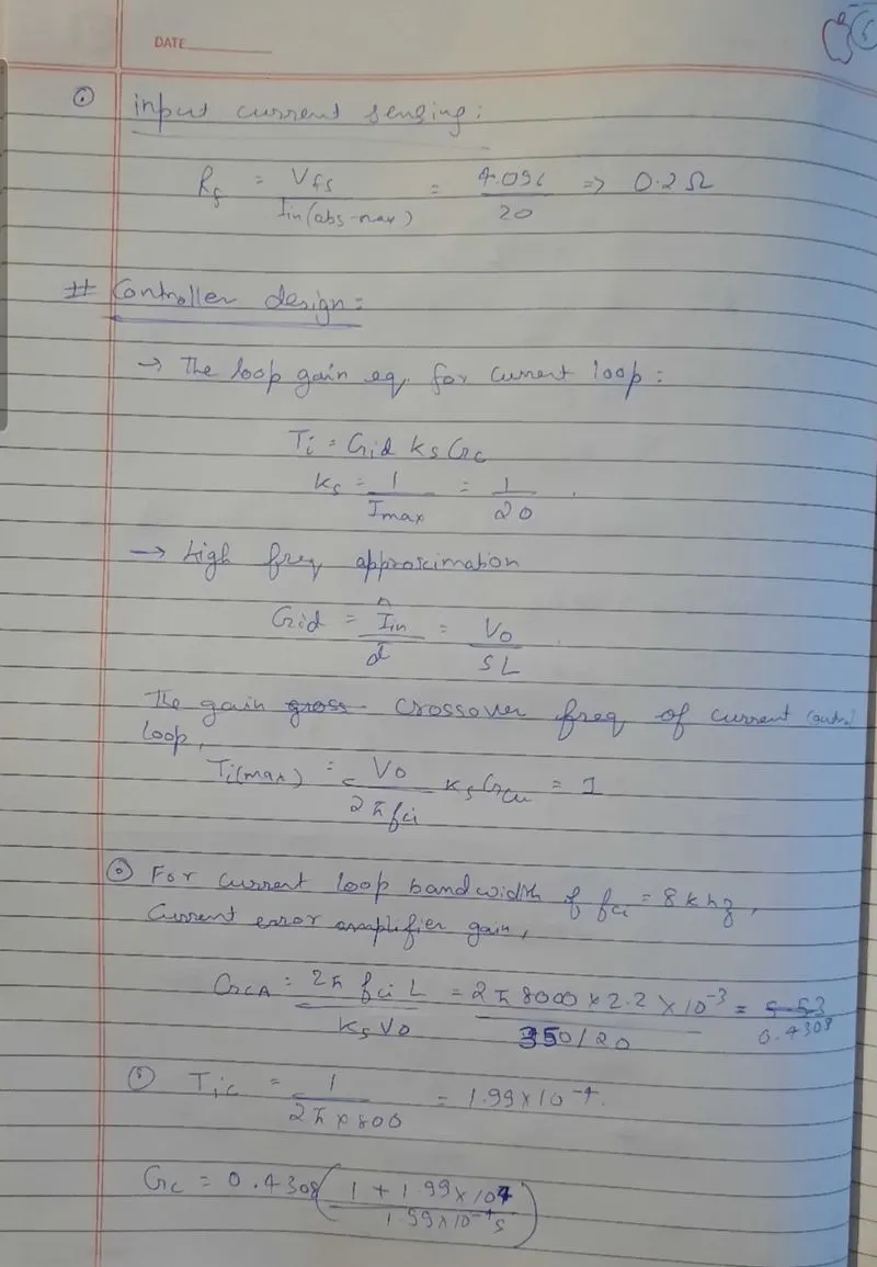
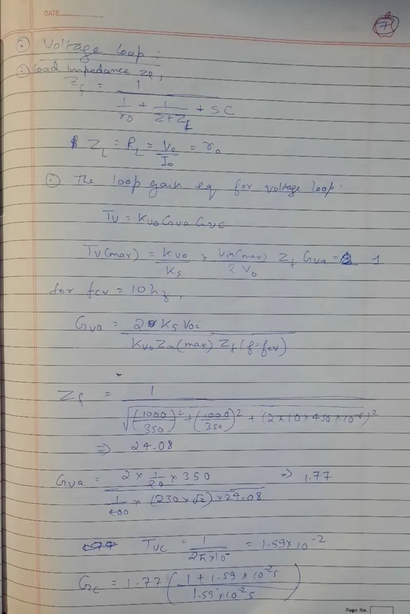
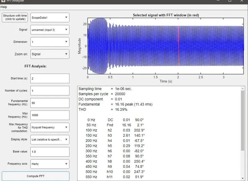
The outputs have been showed and we can see that the output voltage iis not reaching to 350V and output current is not reaching as per required criteria. fromt the fft analysis the thd and power factor can also seen, which is not meetng the prescribed range.
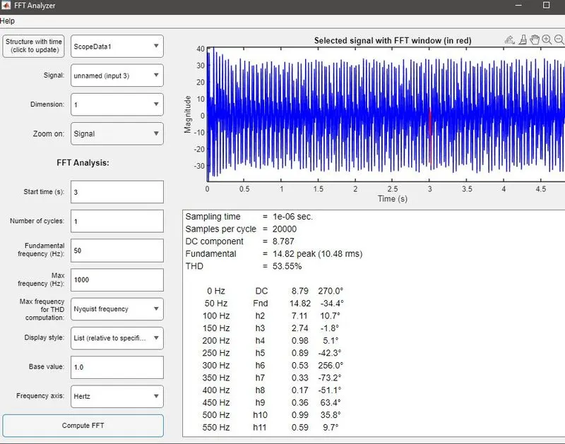
hence, after doing hit and trail method and changing few values the resuts were better:
Cout:
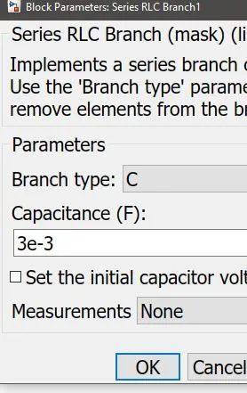
Cdc link:
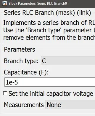
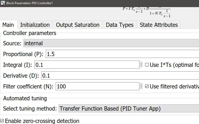
voltage controller:

current controller:
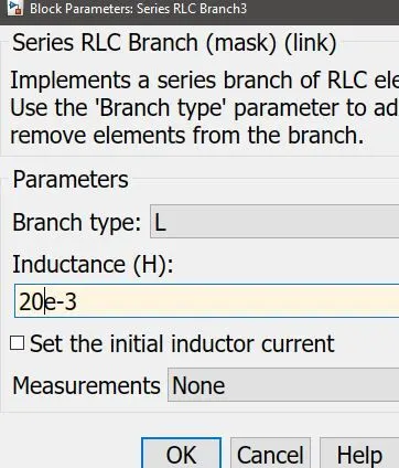
source inductance:
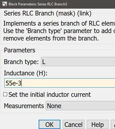
Lout:
OUtputs:
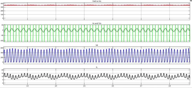
from the output we can see that the results are better than the first case calculated values.
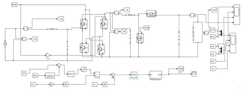
2. PWM rectifier:
the values in the first case is same and pid tuning was done by hit ad trail method:
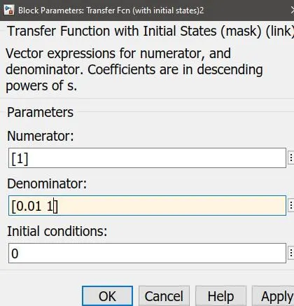
Voltage controller loop low pass filter:
current controller:
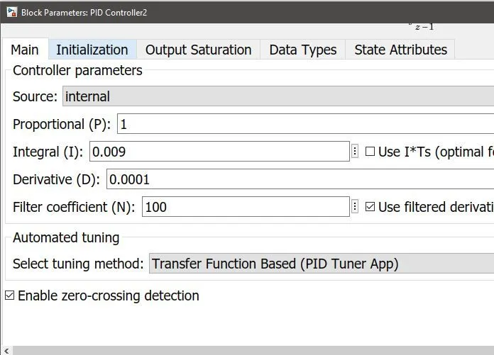
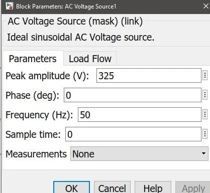
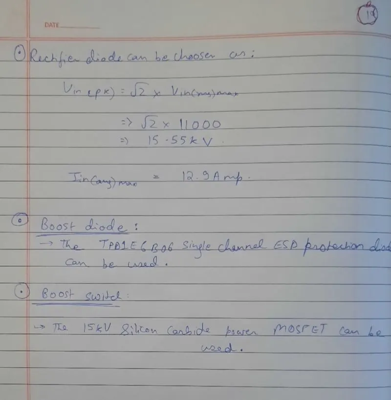
Vinput:
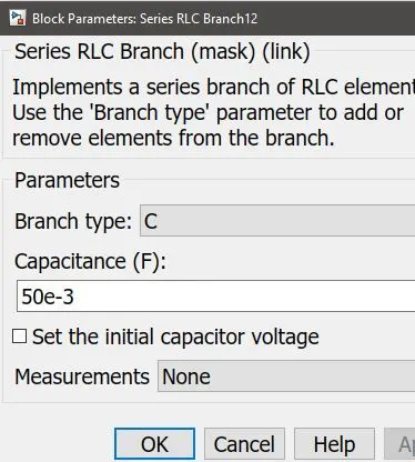
Cout:
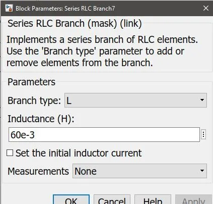
Lout:
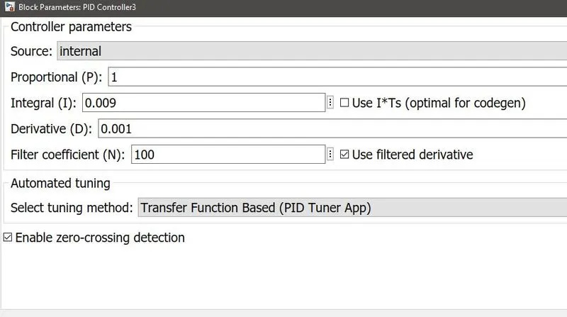
VOLTAGE controller:
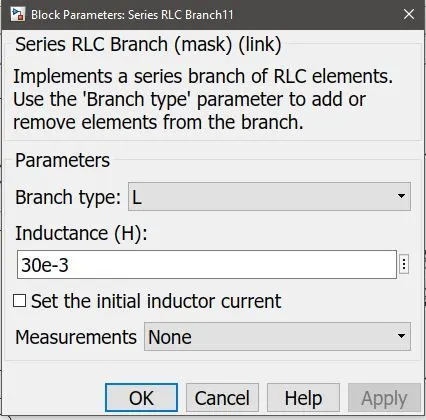
Lout:
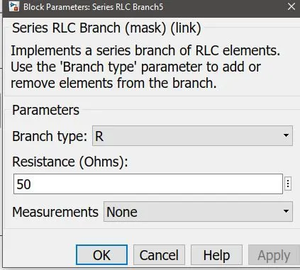
Load:
output:
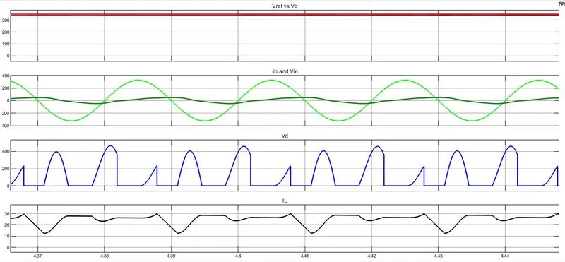
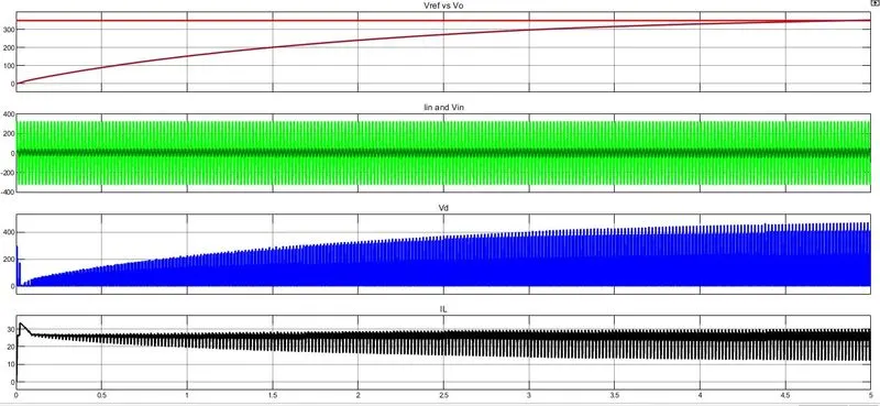
The outputs have been shown. the PID may have been tuned better for better results.
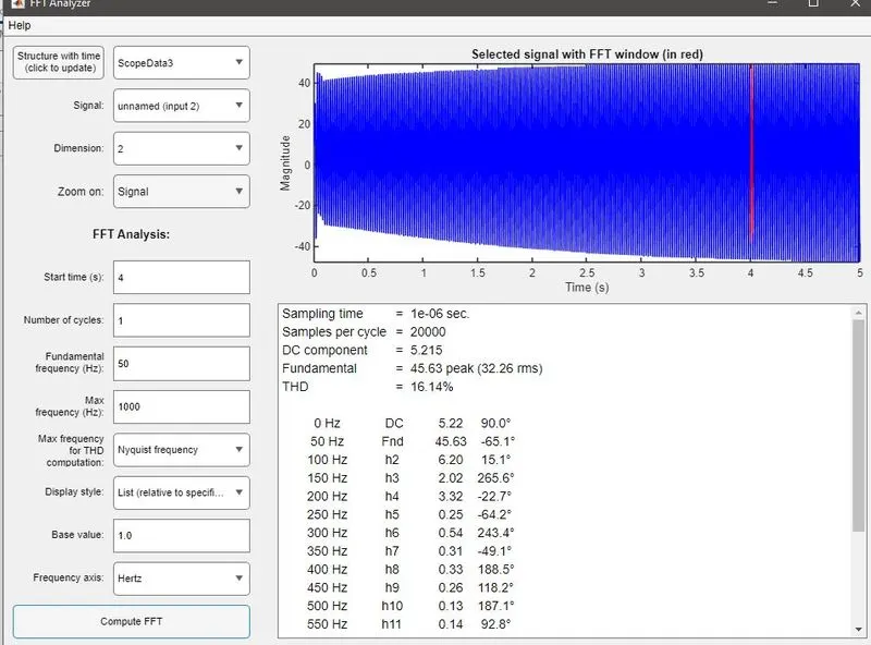
The major difference in PFC and PWM rectifier circuit is that in PFC the output can be achieved easly, but in pwm it was very difficult to reach to output. the controller parameter calculation was complex in pfc method and was less complicated in pwm. but the exact value for pwm has to be modified using hit and trail method. both can be used as 2 degree freedom systmem. the efficiency of wm method is high.
3.
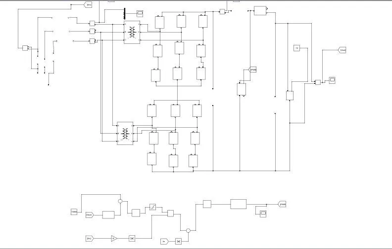
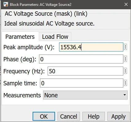
HVDC system
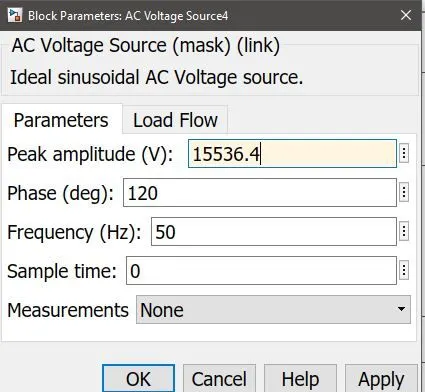
Vc:
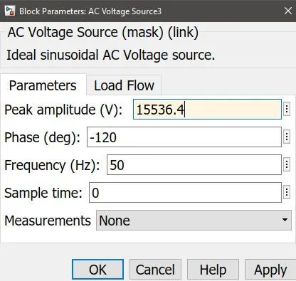
Vb:
Va:
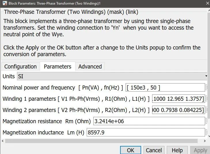
Transformer star:star
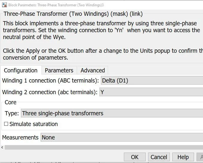
Transformer 2: delta:star
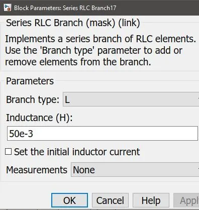
Lout:
dc link capacitance:
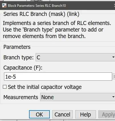
Cout:
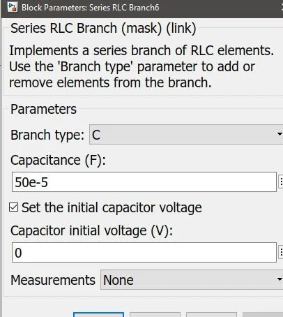
Outpputs:
Vin:
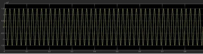
Il:
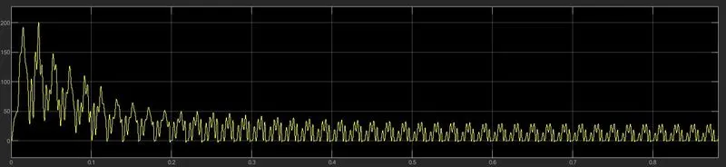
Iin:
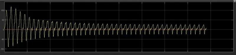
Vout:
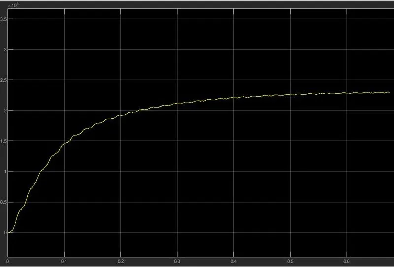
FFt: