Preprocessing of a car suspension model using CAE ANSA
Preprocessing of a car suspension model using CAE ANSA
Aim :- To mesh the rear suspension of car in given mesh parameters and quality parameters and deploy proper connection on it.
Software used :- Beta CAE ANSA V19.1.6
Abstract :- In this project , I have taken half section of a car rear suspension model for 1D, 2D, and 3D meshing and deploying proper connections. The components having thickness is less than 5mm captured by mid-surface extraction i.e. 2D meshing or shell meshing, and other components are meshed by tetra meshing and springs are captured by 1D meshing.
Given quality parameters :-
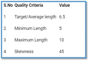
Fig. G.1 Quality parameters for tria element (Tyre and rim )
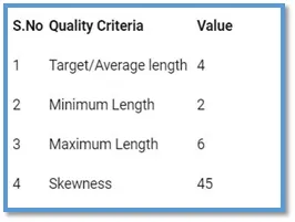
Fig. G.2 QP for other tria (other components)
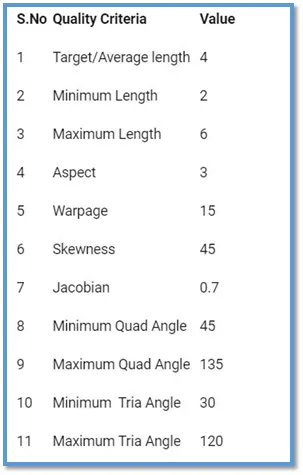
Fig.G.3 QP for mixed type of elements
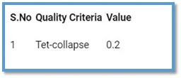
Fig. G.4 QP for tetra elements
Methodology :-
- Import CAD model into ANSA.
- Topology and geometry cleanup.
- Part segregation and assigning PID to each parts.
- Assigning quality parameters and meshing parameters.
- Mid surface extraction for parts having uniform thickness having less than 5 mm thickness.
- Shell meshing and rectifying off elements.
- Volume defining and volumetric mesh generation for grater than 5 mm thickness components.
- Checking for tetra collapse and rectifying it.
- Implementation of connections at required areas.
Introduction :-
Suspension system : The suspension system prevents vehicle from the road shocks and vibration which would be transferred to the passenger in it and it also keeps the tyre in contact with roads. Following are main functions of vehicle suspension system :
- Ride comfort
- Keeps the wheels in contact with road
- Vehicle handling
Types of suspension system :
1] Independent suspension system : Independent suspension system means that the suspension is set-up in such a way that allows the wheel on the left and right side of the vehicle to move vertically independent up and down while driving on an uneven surface. A force acting on the single wheel does not affect the other as there is no mechanical linkage present between the two hubs of the same vehicle. In most of the vehicles, it is present in front wheels.
This type of suspension usually offers better ride quality and handling due to less weight. The main advantages of independent system is they require less space, they provide easier handling, low weight, etc. Examples of Independent suspension are double wishbone and Macpherson strut
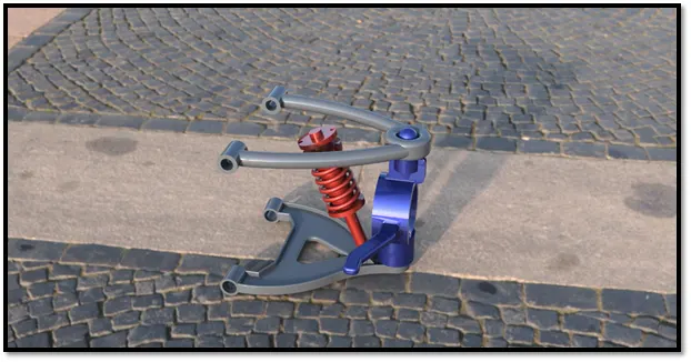
Fig. I.1 Double wishbone suspension
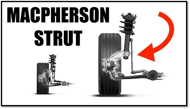
Fig.I.2 Macpherson strut
2] Dependent suspension system : In dependent suspension system there is rigid linkage between two wheels of same axle. A force acting on one wheel will affect opposite wheel. It is mostly seen in heavy duty vehicles. It can bear shocks with great capacity than independent suspension system.
Example of dependent suspension system is solid axel.
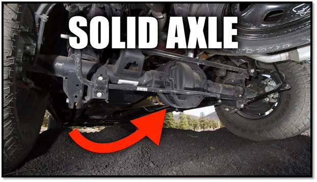
Fig I.3 Solid axle
3] Semi-dependent suspension system :- In semi-dependent suspension system wheels move relative to opposite wheel as in independent suspension system but the position of one wheel has affect on opposite wheel. It has characteristics of both dependent and independent suspension system
Example of this suspension system is twisted beam
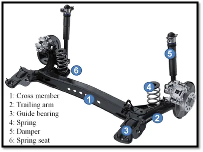
Fig. I.4 Twist beam suspension
Difference between dependent and independent suspension system is shown in below image.
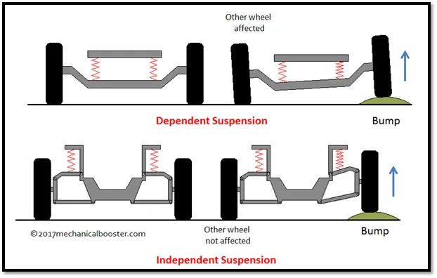
Fig. I.5 Difference between dependent and independent suspension system
Components of car suspension system :-
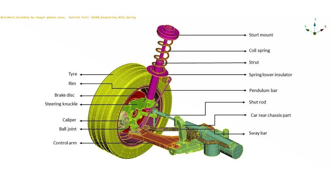
Fig. I.6 Components of rear car suspension model
Strut :- It is a structural part of the suspension system and are mounted to the chassis of the vehicle. A complete strut assembly is a combination of two main parts: a spring and a shock absorber. The spring, which is almost always a coil spring (in other words, one shaped like a spiral), supports the weight of the vehicle and absorbs large bumps. The shock absorber, which is fitted either above, below, or right down the middle of the coil spring, also supports some or all of the vehicles weight but its main function is the same as that of any shock absorber, namely to dampen vibrations. It stops the vehicle from bouncing up and down after a bump.
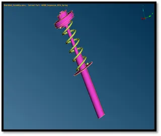
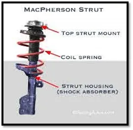
Fig. C.1 Strut model in ANSA Fig. C.2 Actual strut
Coil Spring:- The coil spring in suspension system has two function supports weight of vehicle and Absorb bumps during driving. In suspension system 4 types of springs are used which is shown in figure below
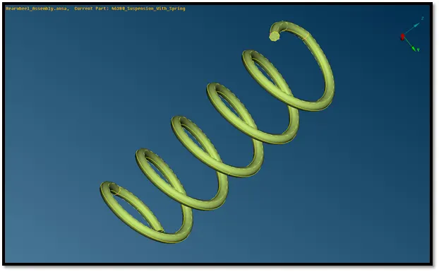
Fig. C.2 Coil spring model used in ANSA
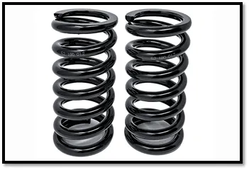
Fig. C.3 Actual Coil spring
In automobile industry generally coil spring is used in suspension system there are 4 types of springs used in suspension system i.e coil spring, leaf spring, Rubber spring and torsion bar
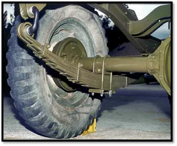
Fig. C.4 Leaf spring
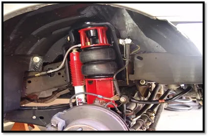
Fig. C.5 Rubber spring
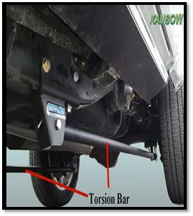
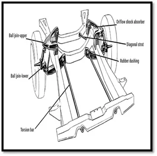
Fig. C.6 Torsion bar
Steering knuckles : Steering knuckles supports the wheel, brake and spring weight of vehicle.the spindle portion of steering knuckle supportds wheel bearing and brake components and allows wheel to rotate on its bearings.
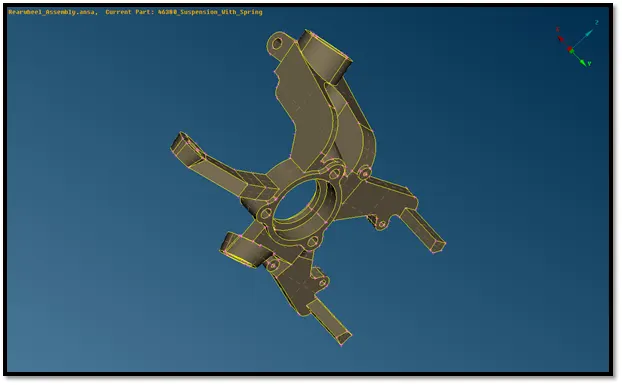
Fig.C.7 Steering knuckle model used in ANSA
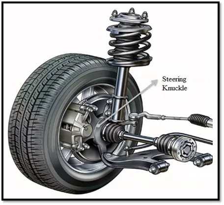
Fig. C.8 Steering knuckle
Wheel hub :- Wheel hub contains wheel bearings which allows to rotate wheel freely with reduced friction. Wheel hub must provide a secure mounting surface for wheel and rim assembly.
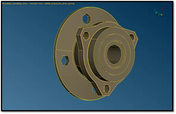
Fig.C.9 Wheel hub model used in ANSA
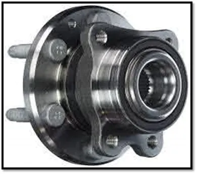
Fig. C.10 Actual Wheel hub
Brake caliper and disk: - Brake calipers are the housing for brake pads. When we apply pressure to the brake pedal, it forces brake fluid through the lines which drives a piston in the caliper to force the pads against the rotors or disc.
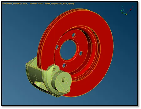
Fig. C.11 Brake caliper and disc model used in ANSA
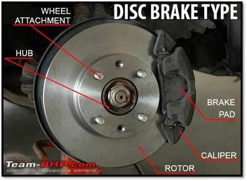
Fig. C.12 Actual component of disc and caliper of brake
Ball joint :- It is a spherical bearings that connect the control arms to the steering knuckles. Ball joint consists of a bearing stud and socket enclosed in a casing. The bearing stud is tapered and threaded, and fits into a tapered hole in the steering knuckle. A protective casing prevents dirt from getting into the joint assembly.

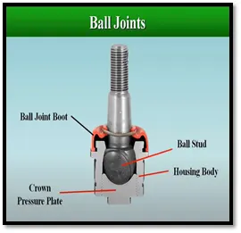
Fig. C.13 Ball joint
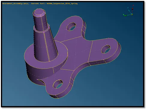
Fig. C.14 Ball joint model used in ANSA
Control arm :- A control arm holds the steering knuckle, bearing support, or axle housing in position as the wheel moves up and down. The outer end of a control arm has a ball joint. The inner end has bushings. A rear suspension control arm may have bushings on both ends.
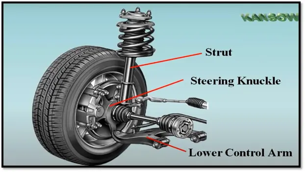
Fig.C.15 Control Arm
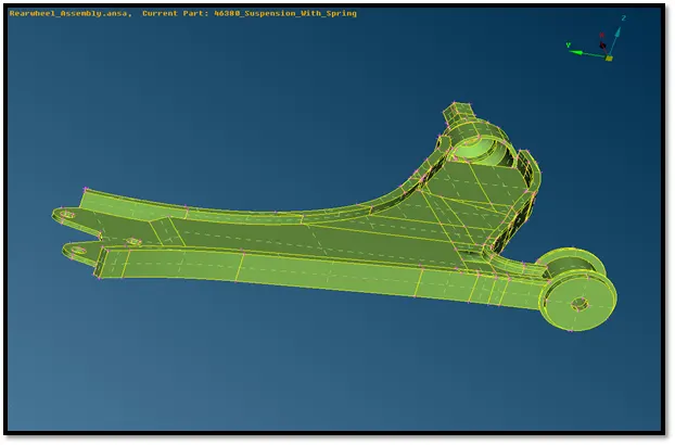
Fig. C.16 Control arm model in ANSA
Sway bar :- It is also known as antiroll bar or stabilizer bar. A sway or anti-roll bar is intended to force each side of the vehicle to lower, rise, to similar heights, to reduce the sideways tilting (roll) of the vehicle on curves or a sharp corners.
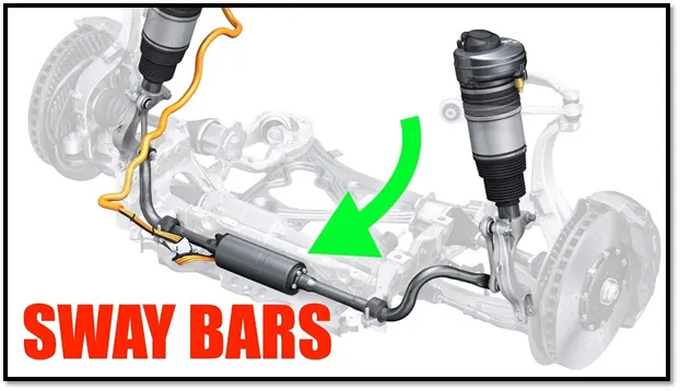
Fig. C.17 Sway bar
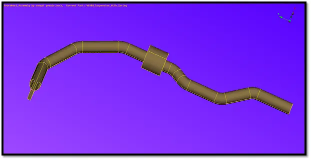
Fig. C.18 Sway bar model in ANSA
Procedure :-
1.Import CAD model into ANSA :-
First, import cad file into ANSA user interface with File > Open option or “Ctrl + o” shortcut key.
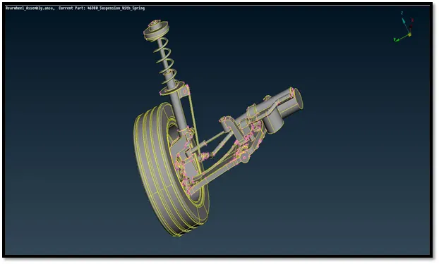
Fig. 1.1 Import CAD model into ANSA UI
2.Topology and geometry clean-up :-
First we have to perform Topo operation over whole geometry for surface stitching to each another. After that, need to check geometry check where unchecked faces, triple coons, sharp edges, needle face, etc geometric errors are checked by ANSA.
In geometry check we get much errors we can fix these errors by auto fix option or we can fix this errors by manually. After clearing we errors we get green tik under status option then we can move further.
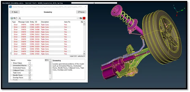
Fig. 2.1 Geometric errors found during geometry clean-up
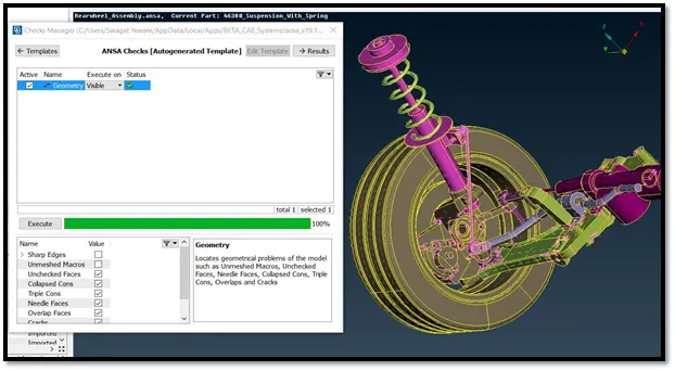
Fig.2.2 After geometric errors cleared manually
3.Part segregation and assigning PID to each parts.
After removing all errors we have to differentiate all the parts under property ID so we can work on them part by part and expedite pre-processing of rear suspension system of car.
Segregation of all components of suspension system under PID is shown in below figure.
Fig.3.1 Components of rear suspension of car
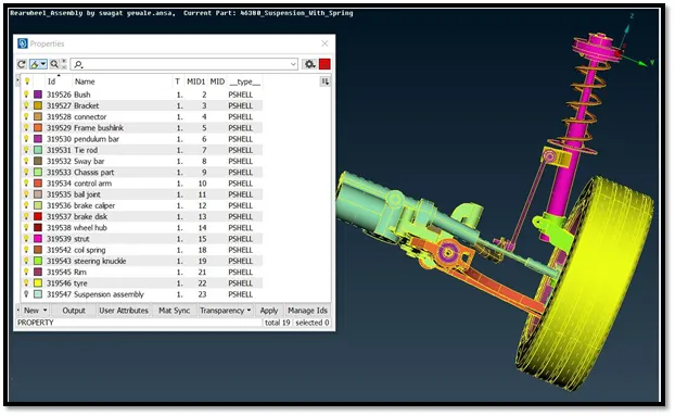
Fig. 3.2 Components segregation under different PID
4.Assigning quality parameters and meshing parameters
Set the given quality and mesh parameters for tyre and rim :-
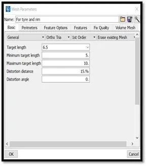
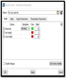
Fig. 4.1 Assigning Mesh and quality parameters for tyre and rim
Set the quality and mesh parameter for uniform thickness components having less than 5 mm thickness
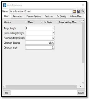
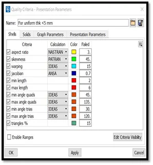
Fig. 4.2 Assigning mesh and quality parameters for uniform thickness components
Set the mesh and quality parameters for other component for shell meshing :-
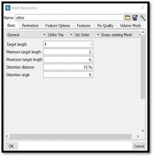
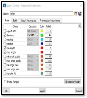
Fig.4.3 Mesh parameter and quality parameter for other component
Set the collapse quality parameter is 0.2 for volumetric meshing.
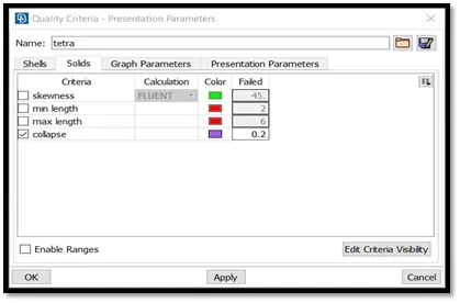
Fig. 4.4 Solid quality parameters for tetra meshing
Theory on quality parameters :-
1] Quality criteria in 2-D meshing :-
- Warp angle :- It is angle between normal of two planes of quad element by spliting it diagonally. The ideal value of wrap angle is 0 degree but it is allowable till 15 degree.
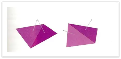
Fig. 4.5 Warp angle
- Aspect ratio : It is defined as maximum edge length of element to the minimum edge length of element. Ideal value is 1 but it is acceptable till 5
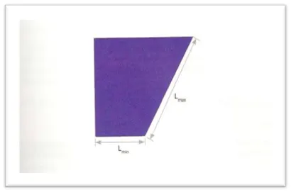
Fig 4.6 Aspect ratio
- Skewness : Skew for quad element = 90 ° – minimum angle between two lines joining opposite mid mid sides of element. (α )
Skew for tria element = 90° - minimum angle between two lines from each node to opposing mid-side and between two adjucent mid-side at each node of elements. Ideal value is 0° and acceptable till 45°
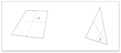
Fig. 4.7 Skewness
- Jacobian :- It is scale factor which arises due to transformation of co-ordinate system. Ideal value is 1 but it is acceptable greater than 0.6
- Mid surface extraction and meshing for parts having uniform thickness having less than 5 mm thickness.
There are 2 parts having uniform thickness which is less than 5 mm on these parts we are going to perform 2 D mesh over it.
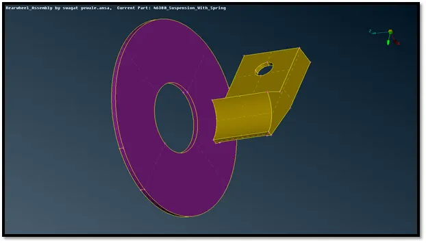
Fig. 5.1 Mid surface need extract for above parts
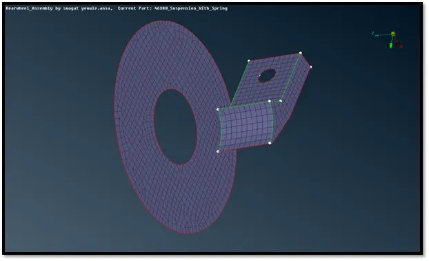
Fig. 5.2 2 D meshing over uniform thickness components
- Shell meshing and mesh improvements :-
For generating shell meshing we use Mesh > Mesh generation > Spot mesh option and mesh components one by one. After that we clear the off elements by reconstruction, smooth, split, join, Mvfree, swap, etc options. Images after shell meshing over all components are given below.
1] Tire :
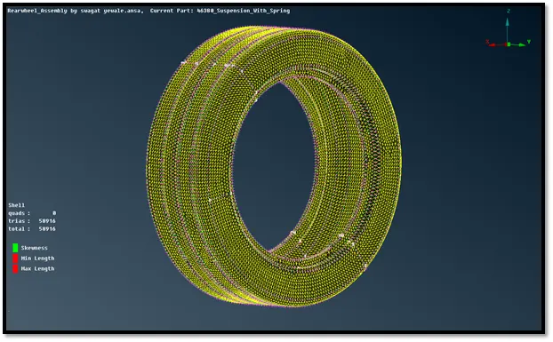
Fig. 6.1 Shell meshing over tyre
2] Rim :-
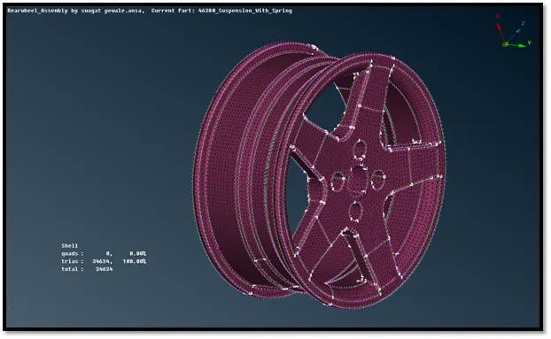
Fig. 6.2 Shell meshing over rim
3] Other suspension components :-
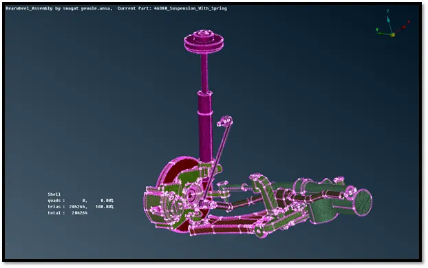
Fig. 6.3 Shell meshing over other suspension components
- Volume defining and volumetric mesh generation for grater than 5 mm thickness components. :-
In volume meshing or tetra meshing or 3 D meshing first, we have to define volume and generate solid tetra elements in shell meshing previously we created but before defining first make sure that components are properly meshed and are having closed volume. Also components should not contain overlap surface.
Define them one by one and set different PID type as a solid as shown in image below using Volume > Define > Manual option.
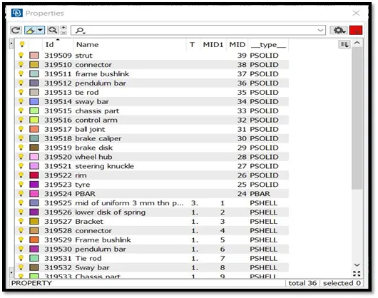
Fig. 7.1 Volume define
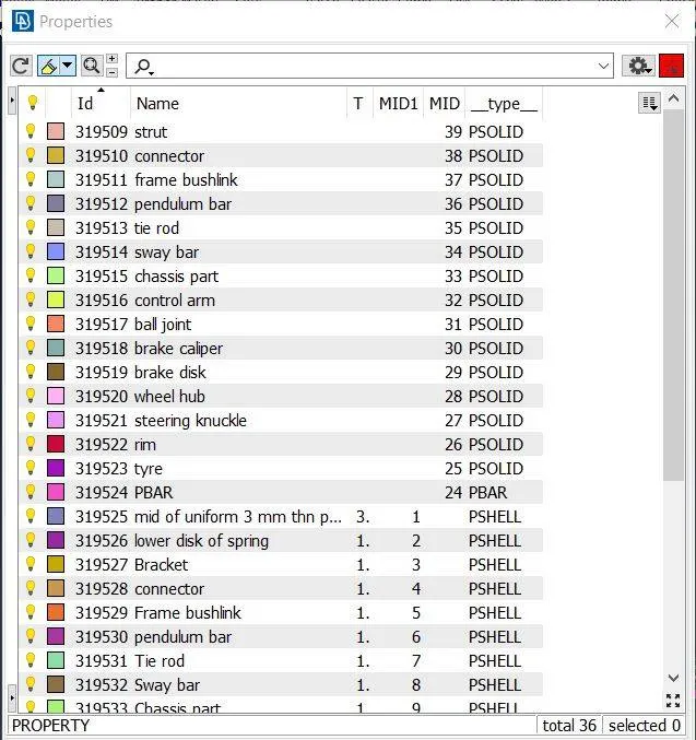
Fig. 7.2 Assigning new PID solid for tetra meshed components
Below are images of some section view of tetra solid element inside the volume.
1.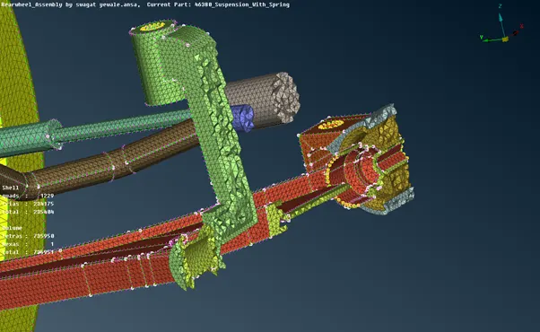
Fig. 7.3 Tetra elements generated inside shell mesh
2.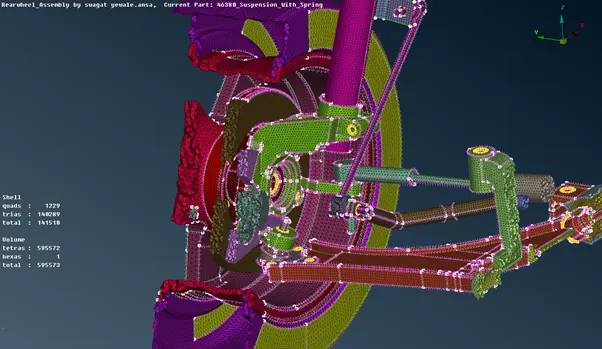
Fig. 7.4 Tetra elements generated inside shell mesh
- Checking for tetra collapse and rectifying it.
Quality criteria in 3-D meshing :-
- Tetra collapse :- Tet collapse is one of the quality parameters, which will be checked while generating Tetrahedral elements. It can be calculated by measuring the distance of a node from the opposite face, then each of the four values will be divided by the Square root of the opposite face’s area. The minimum of four resulting values is then normalized by dividing it by 1.24.
Generally tetra collapse can be calculated by the formula = Min of (h/√A) ÷ 1.24
In that formula, “h” represents the Height, between the Node (N1) and the opposite face of the Triangle. “A” represents the Area of Opposite Face (area of the Triangle).
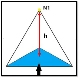
Fig. 8.1 Tetra collapse
In this project quality criteria given for tet collapse is 0.2 . Here, no any off elements is generated if it generates we can easily remove with help of Mv-Free option.
9.Implementation of connections at required areas.
After properly meshing and rectifying off elements we proceed to connections at required areas with the following types:-
1.RBE2 Cluster connection :- In this RBE2 cluster connection, we provide connection to two or more holes on two or more surfaces which nearer to each other and lock their movement in all axes during simulation and all degree of freedom so that they cannot move in any direction which makes them as rigid body during the noise, vibration and harshness simulation in NASTRAN. For generating this connection we use Elements > RBE2 > Many nodes option under NASTRAN deck.
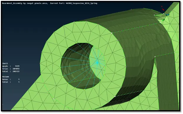
Fig. 9.1 Cluster RBE2 connection
- RBE2 Spider Connections:- In this type of RBE2 connection, we provide connection to one hole which is present on the model to make it rigid in all the axis which avoids any movement during simulation. We provide these types of connections were independent holes present as shown in the image given below:
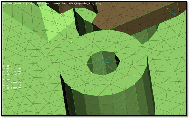
Fig. 9.2 Spider connection
3) RBE2 Two Node Connections :- In this type of RBE2 connection, we provide connections where need to represent rigid bolt element connection in a model. we can give this type of connection with Elements > RBE2 > Two node option.
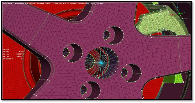
Fig. 9.3 RBE2 two node connection with stem for wheel rim and wheel hub
4) C-Bar Connections for spring :- in C-Bar connection, We try to capture spring as a FE element instead of meshing it We first create a curve of the spring using the Middle option in the Curves tab under TOPO module and then we use the NASTRAN module and under elements select the C-Bar option. On selecting it a dialogue box opens having options for how the C-Bar has to be represented namely nodes, Curves(sea). Curves(box), node sets and edges. Select the Curves (box) option and then we need to create a new PBar Property. On Confirming, we get spring which is captured with 1D elements as shown in the image below.
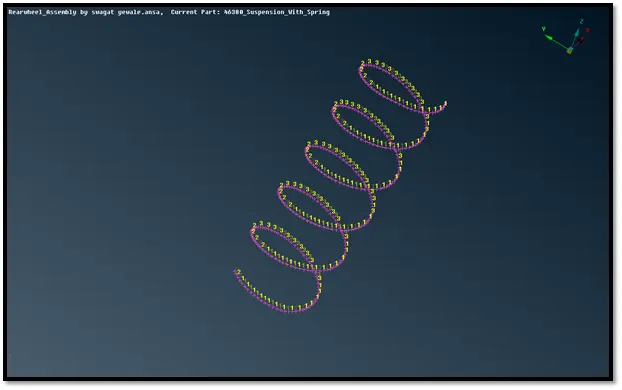
Fig. 9.4 Cbar connection for spring
Deploying Symmetry to the Model:
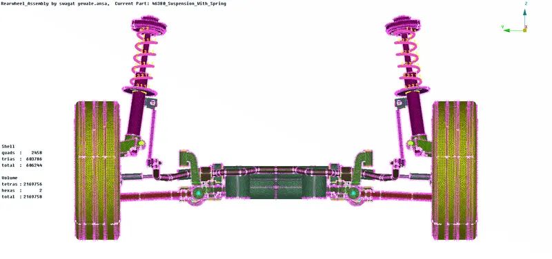
After giving connections, we have to deploy symmetry to the model so that the system would look complete For this, we go to the Transform option under Utilities tab and we select the entities needed to be given symmetry, on comfirmation we have to select default symmetric plane so as to get the symmetry. Finally, we obtain the complete model as shown in final results.
Final results
 .
.
Fig. 10.1 Final assembly in PID view mode
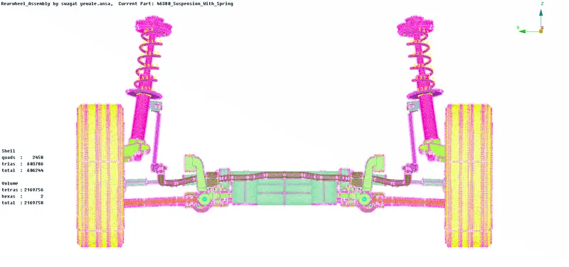
Fig. 10.2 Final assembly view in hidden view mode
Conclusion :- All the components of rear suspension system of car model is complitely preprocessed i.e. 1D, 2D and 3D meshed as per requirement in given quality parameters and deploying proper connections. There are total 2169756 tetra elements generated under shell mesh without any tet collapse of value 0.2 The mid surface components are meshed with 98.32% quad elements and 1.68% tria elements only which is good quality mesh without any off elements. The final obtained model has smooth surface and free from rise and kinks which is can be consider for further processing.
Learning outcome :-
- Car suspension components and their purpose
- Geometry cleanup and checking
- Mid-surface extraction for complicated areas
- 1D, 2D and 3 D meshing
- Implimentation of proper connections.