Project 2
PROJECT - 2
Objective
To check the geometrical errors in the given component and mesh with the given element quality criteria. Mid-surface extraction and thickness assignment is to be done for components having uniform thickness less than 5 mm and tetra volume meshing is to be done for all other components. The mesh quality criteria for midsurface, tyre, rim and other components are given below.
Quality Criteria for Mid Surface Components
| SL No | Quality Criteria | Value |
| 1 | Target/Average Length | 4 |
| 2 | Minimum Length | 2 |
| 3 | Maximum Length | 6 |
| 4 | Aspect Ratio | 3 |
| 5 | Jacobian | 0.7 |
| 6 | Warpage | 15 |
| 7 | Skewness | 45 |
| 8 | Minimum Quad Angle | 45 |
| 9 | Maximum Quad Angle | 135 |
| 10 | Minimum Tria Angle | 30 |
| 11 | Maximum Tria Angle | 120 |
| SL No | Quality Criteria | Value |
| FOR TYRE AND RIM | ||
| 1 | Target/Average Length | 6.5 |
| 2 | Minimum Length | 5 |
| 3 | Maximum Length | 10 |
| 4 | Skewness | 45 |
| 5 | Tet Collapse | 0.2 |
| FOR OTHER COMPONENTS | ||
| 1 | Target/Average Length | 4 |
| 2 | Minimum Length | 2 |
| 3 | Maximum Length | 6 |
| 4 | Skewness | 45 |
| 5 | Tet Collapse | 0.2 |
Introduction
The suspension system of a car consists of tires, shock absorber, frame and linkages that connects a vehicle to its wheels and allows relative motion between the two. The primary job of a suspension is to maximize the friction between the tires and road surface to improve steering stability, handling and ensure comfortable ride quality for the passengers. Figure 1 shows the suspension system of a car which is taken as a model for this project.
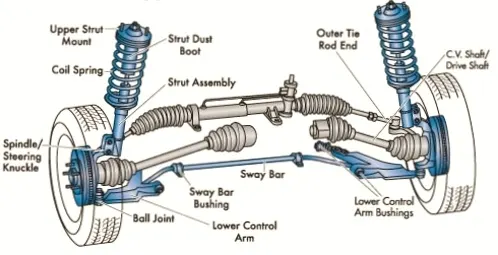
Figure 1. Car Suspension System
Procedure
The given file is imported into ANSA and then geometry clean up, mid-surface extraction, thickness assignment and meshing is done successively. The details of each of these steps are discussed below.
1. Geometry Clean up :
After importing the model, Geometry Clean-up is performed to remove unchecked faces, needle faces, cracks, collapsed cons and triple cons by removing the unnecessary cons and hot points and stitching the surfaces properly using Topo. Figure 2 shows the model before geometry clean-up.
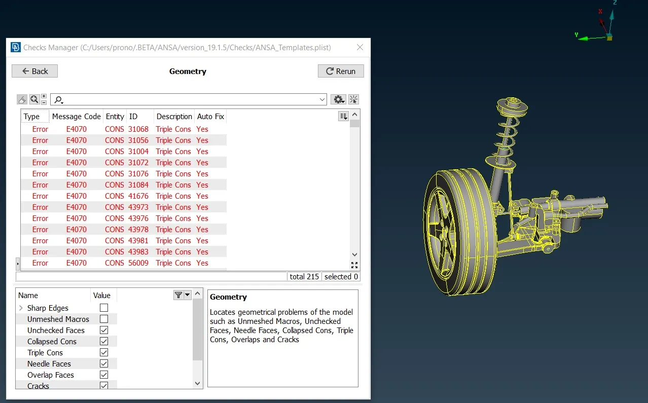
Figure 2. Model before Geometry Cleanup
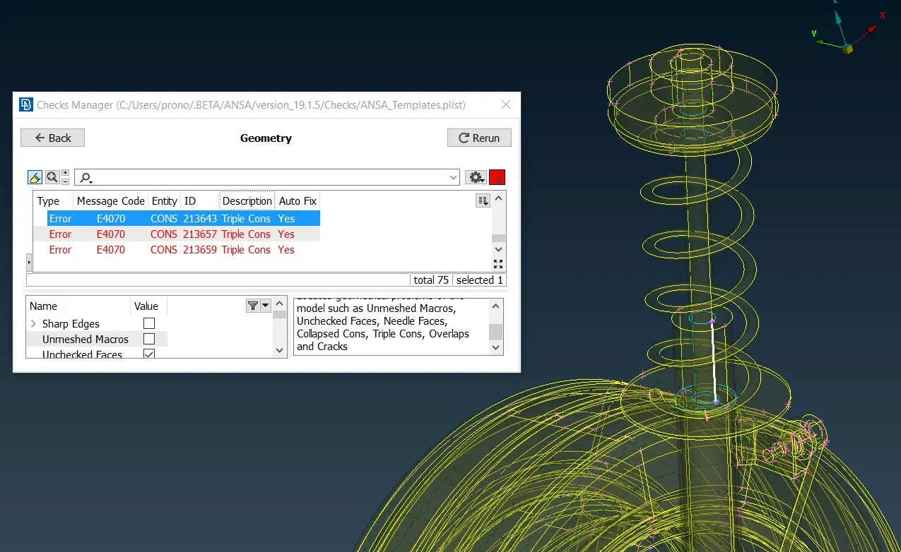
Figure 3. Presence of Triple Cons in the Model
The unnecessary triple cons are removed from the components and new faces are created wherever necessary as shown in Figure 3 and Figure 4.
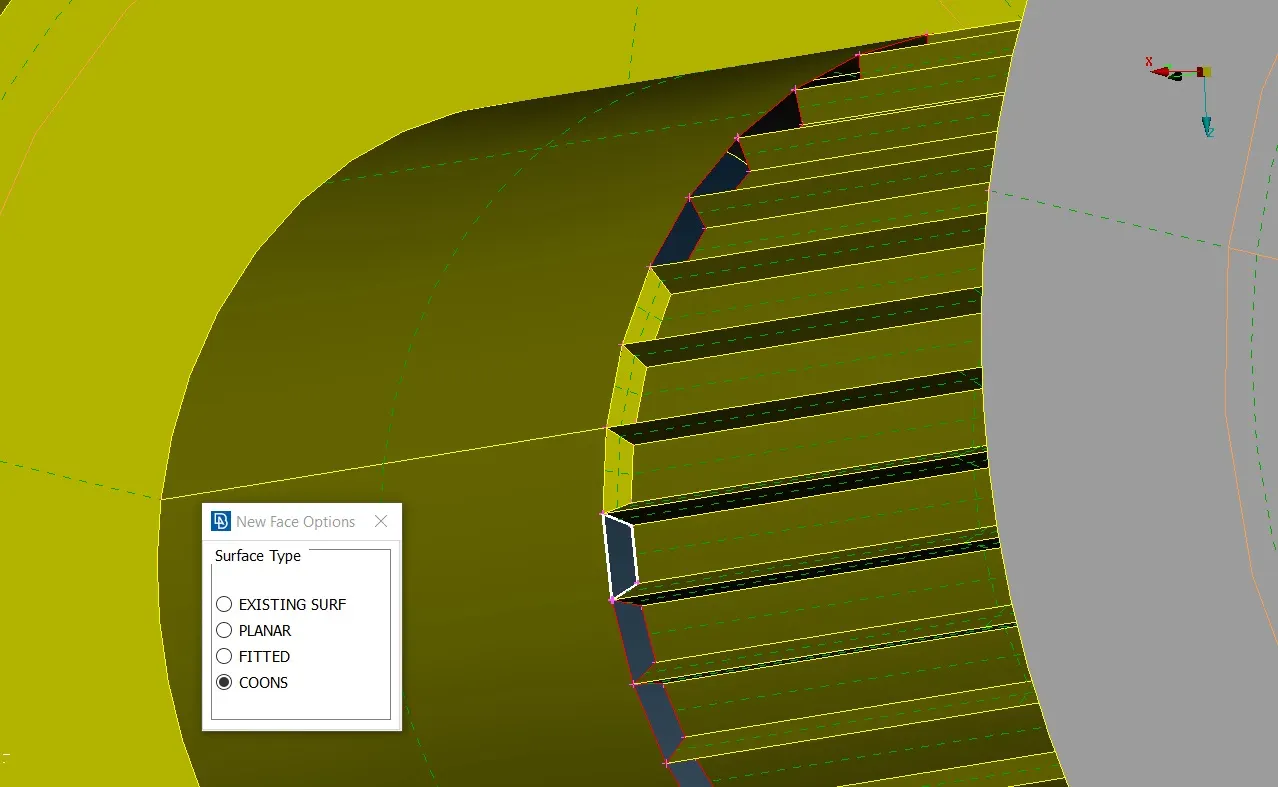
Figure 4. New Coons Surface to Fill Unchecked Faces
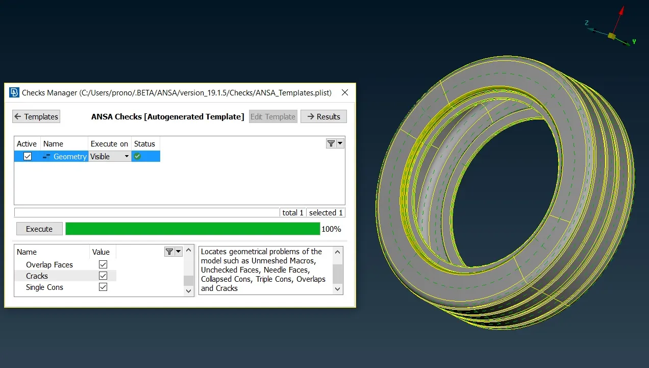
Figure 5. Tyre after Geometry Cleanup
2. Meshing
Before meshing each component the perimeter length is set to target element length, the edge of the holes is slided parallel to surface and even number of edges is ensured in the holes using (Perimeters->Number) option. The top of the beads and fillets are also captured using the (Cut) option. The quality criteria is assigned in the Mesh Parameters and the faces are meshed using the (Best Mesh) option. For achieving a better mesh flow commands like (Num +/-, Shell Mesh-> Reconstruct/Smooth, Elements-> Split, Swap, Join, Grids->MVFree) are used.
2.a Meshing for Tyre and Rim
The shell mesh is generated initially for the Tyre and Rim as per the given quality criteria using manual tria/ortho tria meshing. Then Volume is defined for both these components and volume mesh is generated using Tetra Rapid Meshing Algorithm.
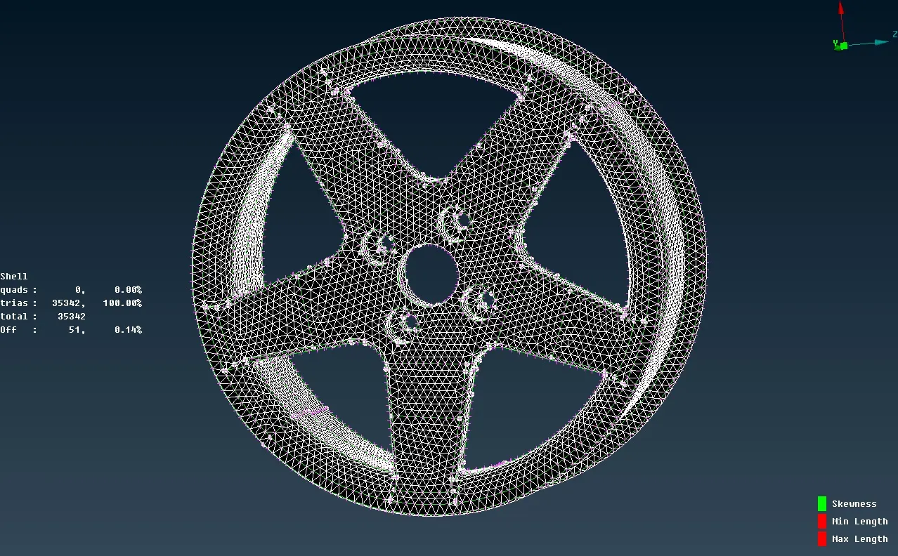
Figure 6. Rim Tet Mesh
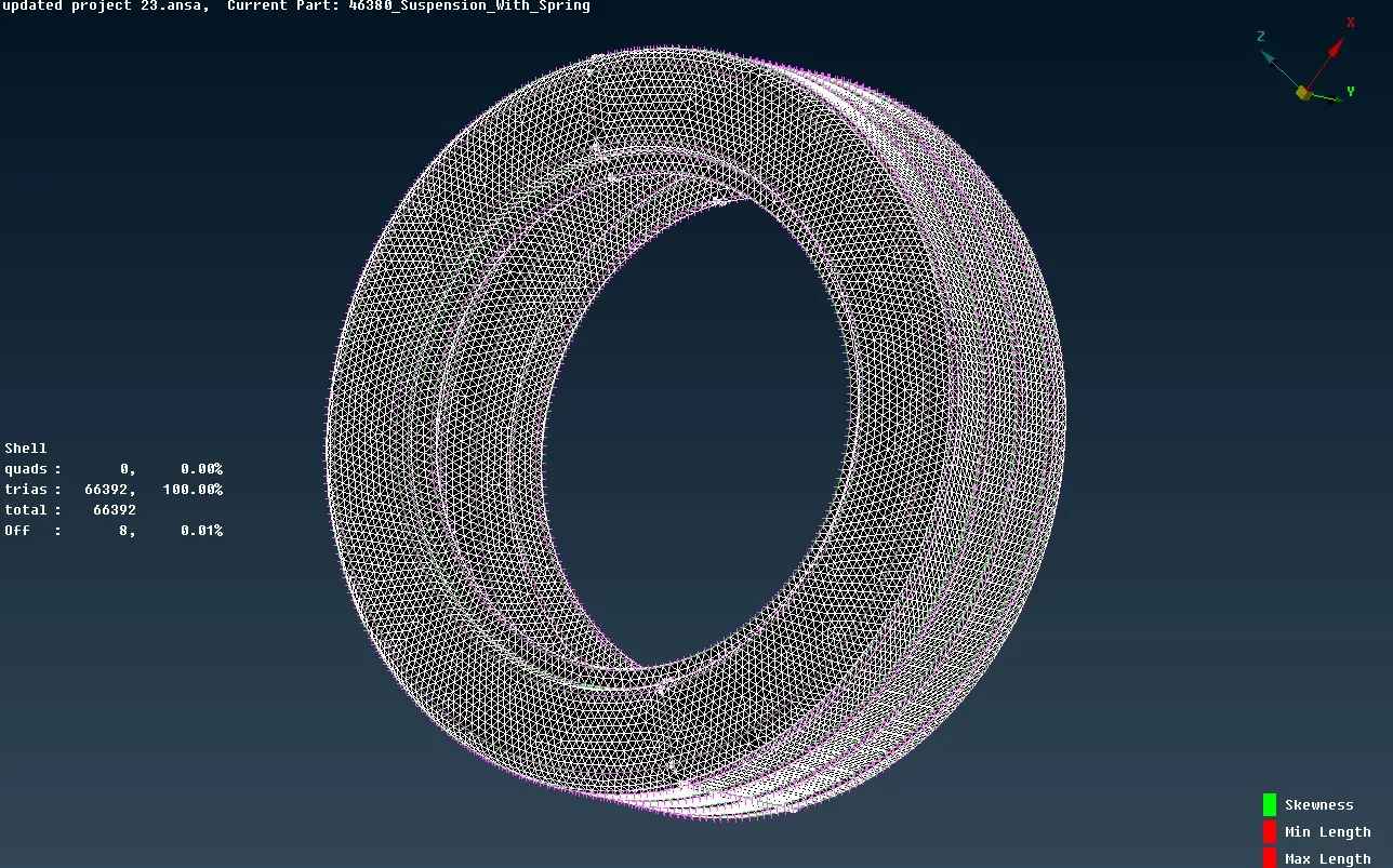
Figure 7. Tyre Tet Mesh
The red bounds are activated to verfiy whether volume mesh is generated successfully or not and tetcollapse quality criteria is also checked.
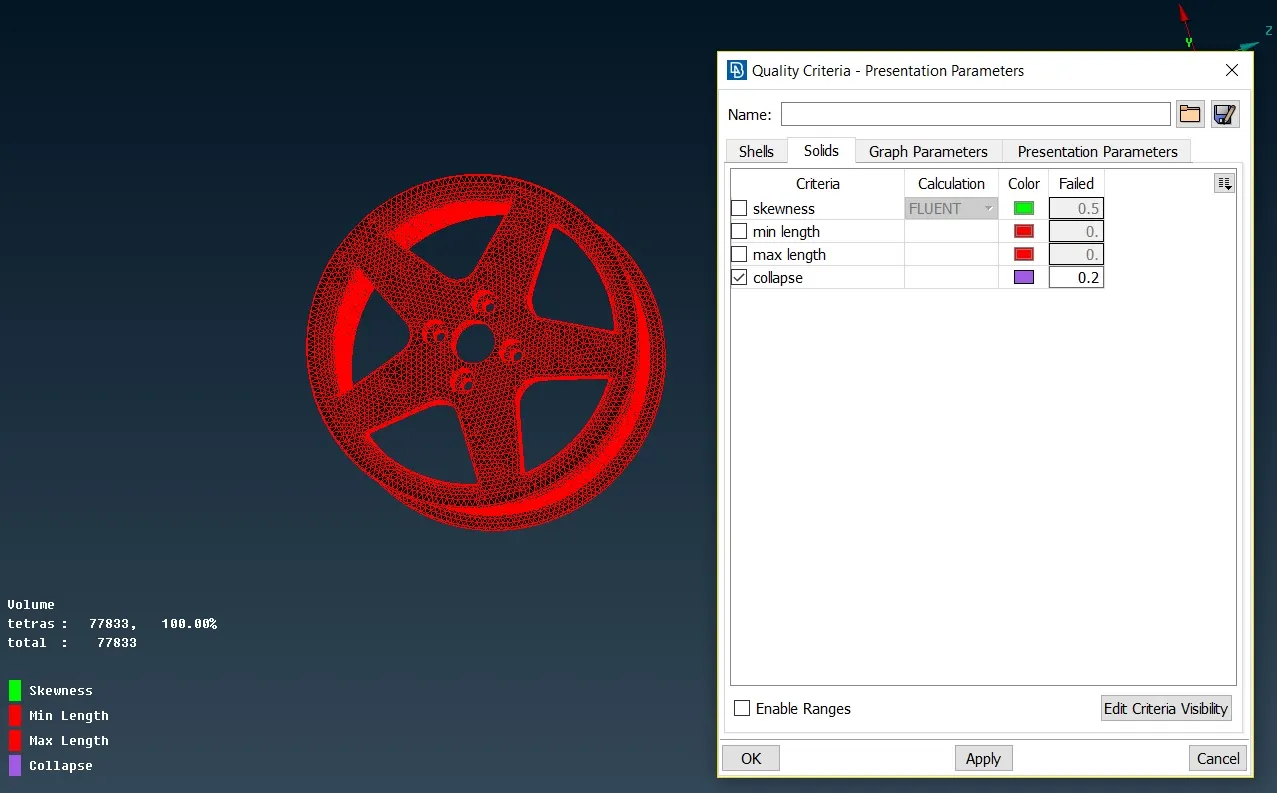
Figure 8. Rim Volume Mesh
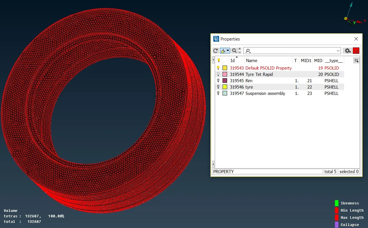
Figure 9. Tyre Volume Mesh
Two components in the model are having uniform thickness less than 5 mm for which midsurface is extracted while all other components are meshed using tria elements. Since half portion of the model is given, the complete model is obtained after meshing by using Transform-> Symmetry option as shown below.
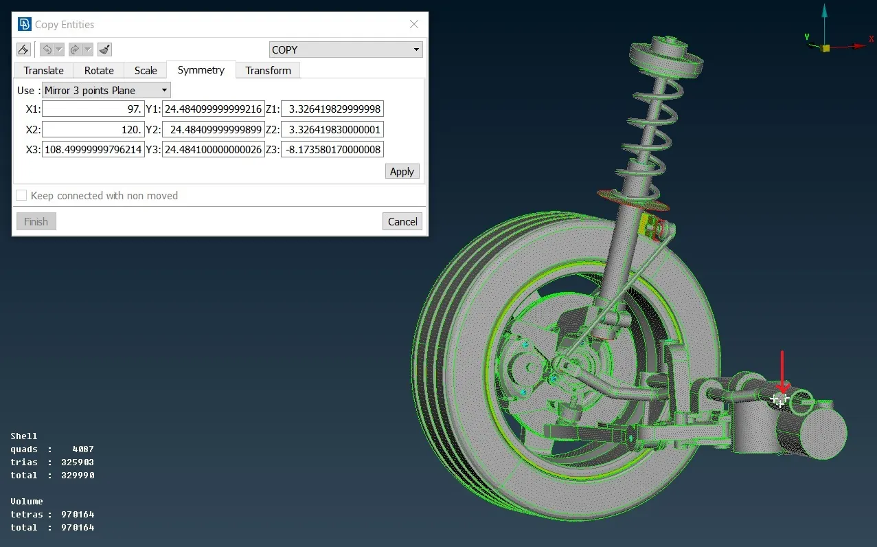
Figure 10. 3 point symmetry option to generate the full model
The downward red arrow shows the position of 3 points for which "Mirror 3 points plane" is used and the complete meshed model for the suspension system is finally obtained as shown in the Figure 11
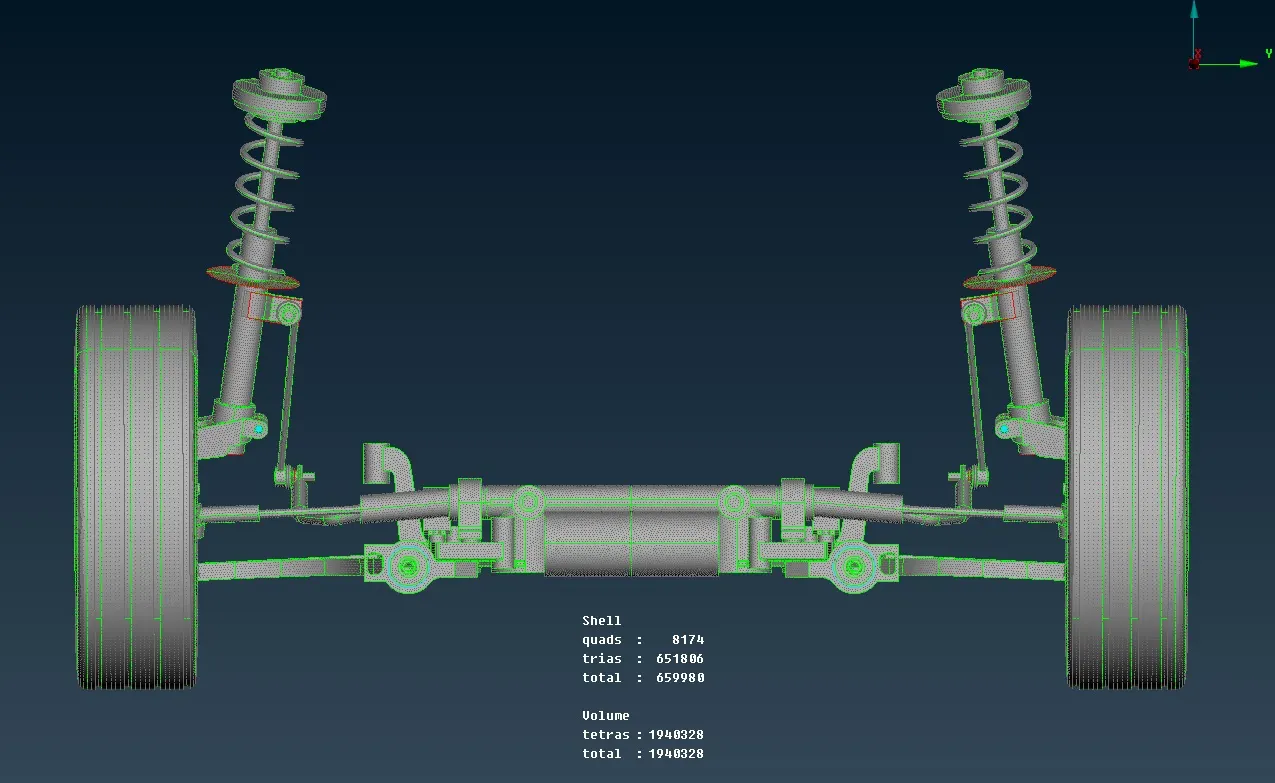
Figure 11. Final Meshed Model
3. Connections
After meshing the entire assembly using shell and volume mesh, connections are assigned to proper locations in the "NASTRAN" deck. This is necessary to analyse the behaviour of the mating components during analysis.
3.a RBE/RBE-2 Connection
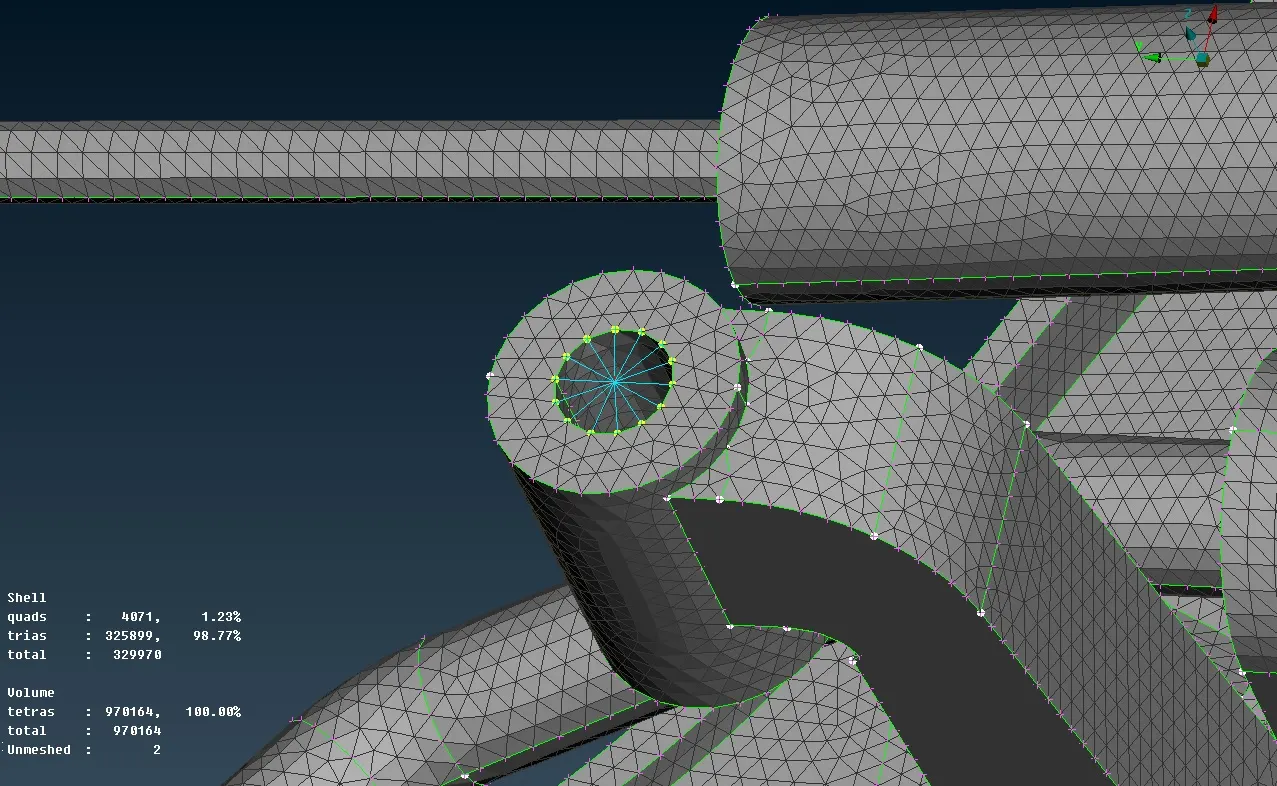
Figure 10. RBE-2 Connection
3.b Seam Weld
Seam Weld is used to connect two mating interfaces which are parallel to each to other and Y joint shell is used for two perpendicular faces. In the present model overlap shell type seam weld is used as shown in Figure 11
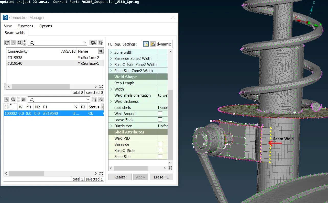
Figure 11. Seam Weld Connection
Conclusion
a) Orthotria elements leads to higher computational time and thus it must be used in specific areas like curved surfaces and holes.
b) Tet meshing is unstructred mesh as the mesh used to fill the volume is not aligned in a structured way.
c) Tetra Rapid algorithm is used for the present assignment as Tetra FEM is to be mainly used for structural applications as mentioned in "ANSA Help".
d) The quality of the volume mesh will depend on mesh quality on the surface of the component and volume mesh can be carried out only if it is closed.
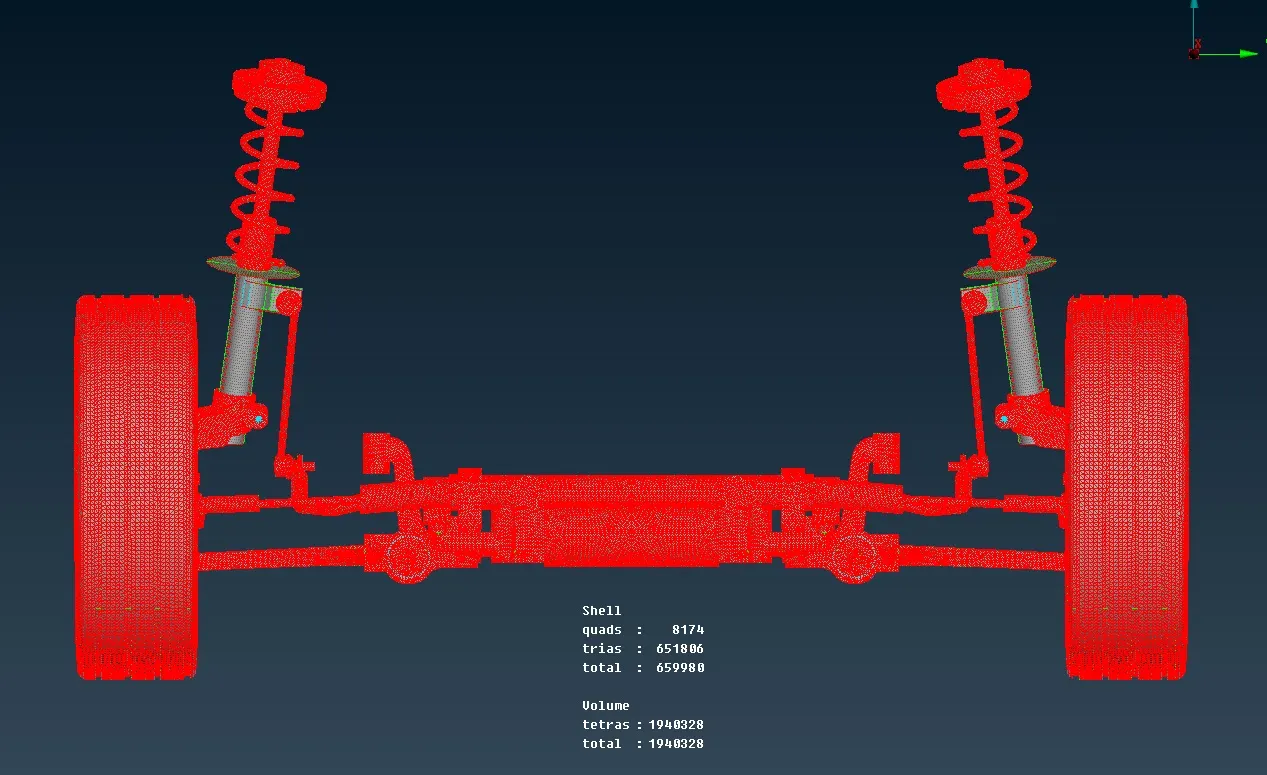
e) For plastic or sheet metal components 2D mesh is generated first and then it can be converted to 3D mesh. For casting components 3D meshing is preferred. All the components in Figure 12 with red bounds are volume meshed and the other are shell meshed as the thickness is uniform and less than 5 mm.
References
[1] Figure 1. Online URL : http://www.asensenada.com/?PageData=service&serviceid=266448