Project 2
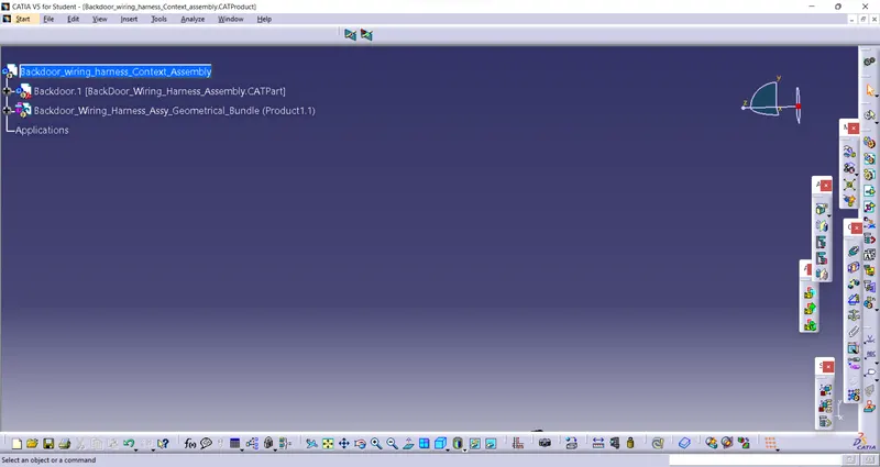
Step 1 - Creating Context Assembly
- A context assembly has created, which will work as a main assembly
- It'll contain BackDoor part file, Backdoor Harness assembly geometrical Bundle along with other part file which will act as external reference purpose
Step 2- Defining C-15663689-1 (4-pole) connector electrically
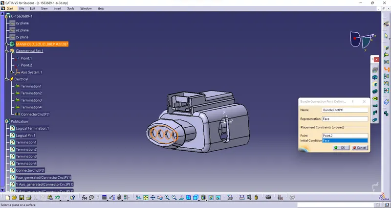
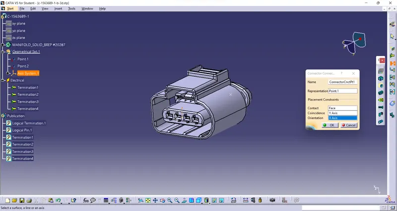
To define C-15663689-1 electrically we have to define geometrical parameters like Bundle Connection Point and Connector connection point in Electric Part Design Workbench
Step 3- Defining C-776438-4 a 12 pole connector electrically
To define electrically we have to define geometrical parameters like Bundle Connection Point and Connector connection point in Electric Part Design Workbench
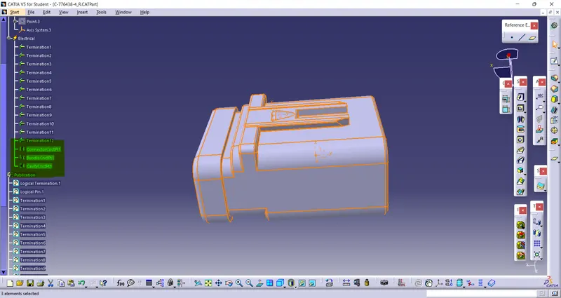
Step 4 - Defining Fir Tree Clip Electrically
we have to define Fir Tree Clip with Geometrical parameters along with entry and exit point and both side of Fir tree clip
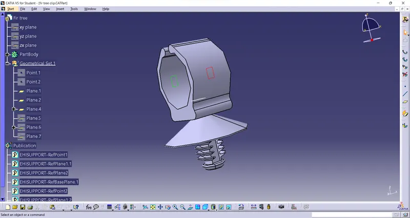
Step 5 - Wiring Harness Assembly
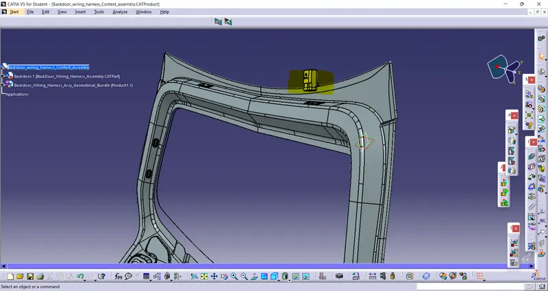
I) Mounting inteconnector C-776438-4 on assembly
Here we will use tools like Manupulation along with Smart Move, Snap and Compass to locate both desired potition and orientation as shown in figure
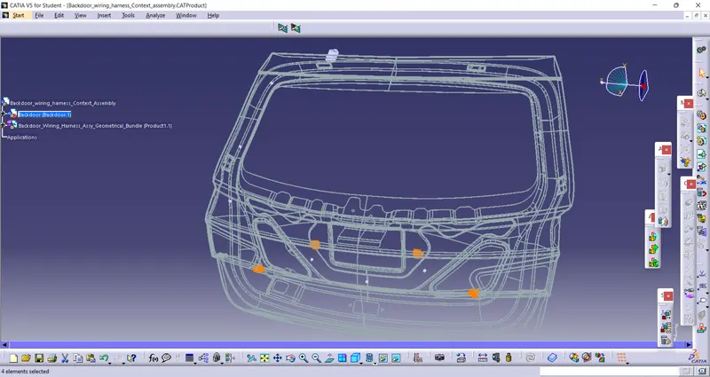
II) Mounting inteconnector C-15663689-1 (4-pole) on assembly.
Here we will use tools like Manupulation along with Smart Move, Snap and Compass to locate both desired potition and orientation as shown in figure
Two C-15663689-1 are for Tail-Gate Light & two C-15663689-1 are for Wiper Motors
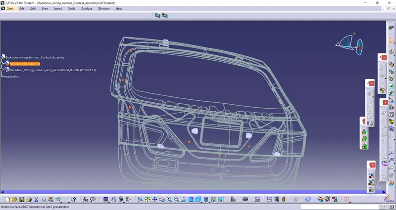
III) Mounting Fir tree clip on assembly.
we will be using appropriate quantity of fir tree clip for smooth rounting and to fix harness on routing path firmly.
Here we will use tools like Manupulation along with Smart Move, Snap and Compass to locate both desired potision and orientation as shown in figure.
Step 6 - Rounting the Bundle in assembly
We will start routing the bundle in Electric Harness Assembly. First of all we have to define BackdoorWiring Hanress Geometrical Bundle electrically by using GEOMETRICAL BUNDLE tool.
We will be using different diameter for different bundles along with required bend radius and slack.
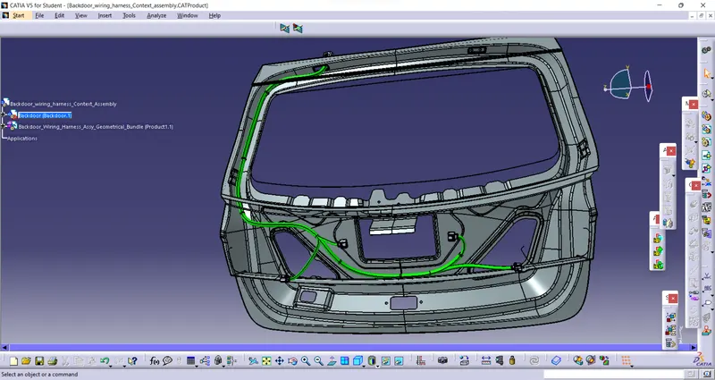
To add BRANCH POINT at desired location we will use ADD BRANCH POINT tool.

Step 7 Adding Protective Covering
We have to add protective covering to required bundles. Based on requirement we can choose protective covering with different different dia. We have to approximately assume the end and start Extremity
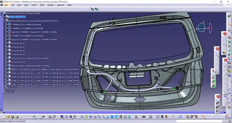
Final wiring harness assembly
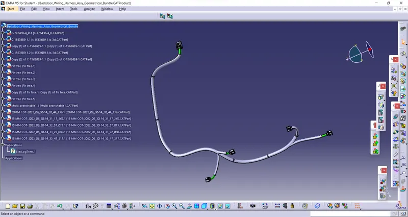
Step 8- Checking Bundle Continuity
Edit>Search>Adveanced>Workbench-Electrical>Type-Bundle Segment>Attribute-Fully Connected
By selecting FALSE it will show all the Non-Connected bundle segments.
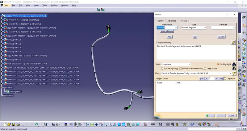
As we can see above there is no bundle found as Non-Connected bundle it means our all Bundles are fully connected.
Step 9- Creating Flattening View
In Electrical Harness Flattening workbench we will flatten our wiring assembly. before that we should make sure the flattening file to be saved in a same location as wiring assembly file
At first as shown in following image we have to define Fattening Parameters
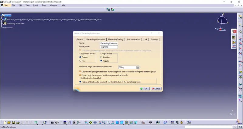
Use Extract tool to extract wiring harness assembly into flattening workbench

we will use Flatten tool to flatten our wiring harness assembly
here we will use different features like Bend,Rotate etc to streamline our harness assembly
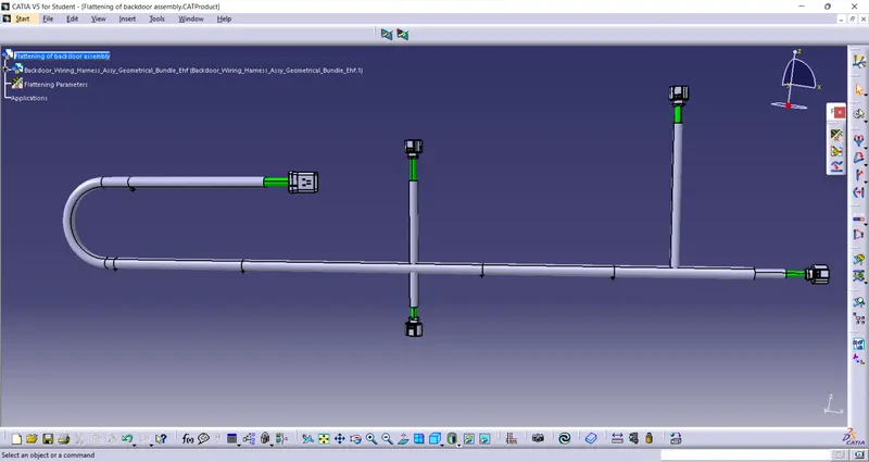
Step 10 Creating Flatten View Drawing
New>Drawing>define Sheets parameters

use flatten view tool to extract flatten assembly into drawing file.
We have to define Drawing parameters as shown below to get require drawing
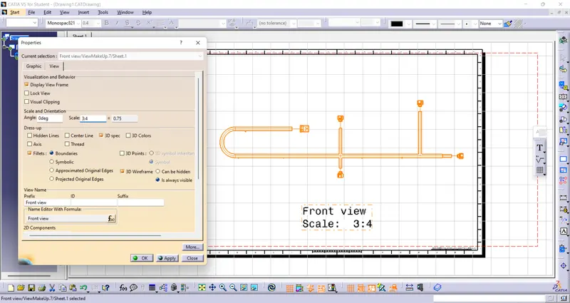
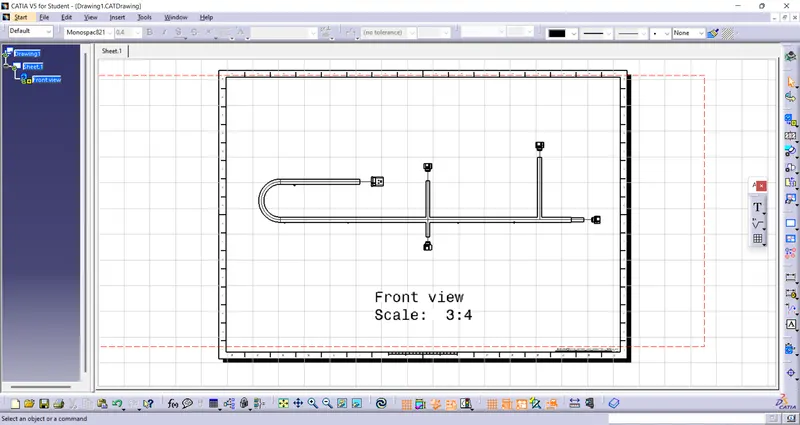
following image is final drawing view of flatten Back door wiring harness assembly