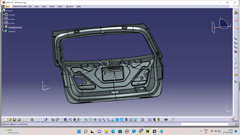
Project 2
AIM:
To Route the Wiring harness on Given car body and Prepare flatten view drawing in CATIA V5. Application of all Packaging rules, Industry best practices studied in this course shall be demonstrated in design. Apply Protection coverings as required.
To define the Electrical component of the connectors and clamps for the Given model for Wire routing.
OBJECTIVE:
To define the Given car body and mount the perfect place of the connectors and clamps in the for the Electrical component such as back light (Rear break and reverse light and Number board lamps) and rear wiper.
To define the connector and clamps in the electrical components by the Electrical Part Design workbench.
To mount the connectors on the deserve position.
After placed the connector to start the routing of bundles.
REQUIREMENT:
Download the required CAD parts in the TE.com of the CAR back door BIW and electrical connectors and clamps.
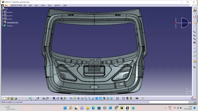
Likewise download the connector parts and clamps in the isg format file.
PACKAGING RULES AND ASSUMPTIONS:
Provide enough clearance to the wiring harness with respect to the surrounding.
Avoid harness routing and clamping in blind zone
Provide additional slack to the harness according to the surrounding. 5-10% of slack.
Branch length should maintain with 50mm.
Minimum distance between clip and nearest branching point should be 25mm.
Minimum distance two breackouts should 50mm.
INTRODUCTION:
A wiring harness is an organized set of wires, terminals and connectors that run throughout the entire vehicle and transmit information and electric power, thereby playing a critical role in “connecting” a variety of components.
GEOMETRY PARAMETERS AND ELECTIRCAL CONNECTOR :
Firstly loaded CAD model make the piont on mating and bundle entry side. Andthen make the axis (Co-ordinate) system of the Connector connection point all in the Mechanicl Design in Part Design.
One things we want understand is Axis system was poistion or orientation of axis
1) X-Axis is orintation of locking mechanism.
2) y-Axis is normal to the another connector.
Define the Electrical connector in Electrical part design system. After declear electrical connector model turns to electric part identify by the wating tree structure. And pop up the dialog box.
Define Bundle Connection point which is terminate wire should be inserted on this side(This point defines where the harness bundle segment point will end when routed to the electrical connector) even there is popup the dialoge box for creating Bundel connection point gives the asked perspectives.
Define Connector Connection point is mating side of connector (This point defines is used for the connection of one connector to another connector) even there is popup the dialoge box for creating Connector connection point gives the asked perspectives.
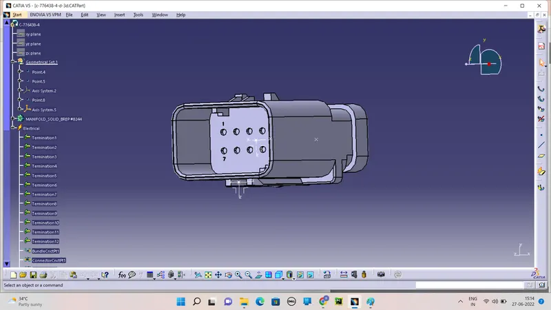
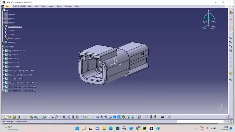
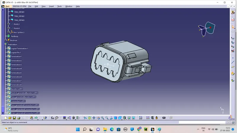
After define the connectors as an Electrical components and define the clamps.
Makes points and planes in the clamps and define is the electrical support as well as by tools of support in the Electrical Part Design workbench.
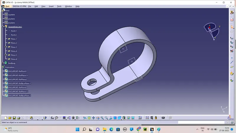
CONNECTOR PLACING:
To place the connectors and clamps to the correct required position of the connectors.
Mount the connectors to the appropriate position by Assembly design workbench tools of Manipulators and compose.
Install all connectors and then start routing.
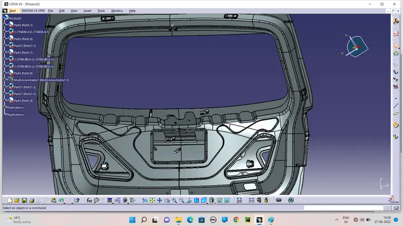
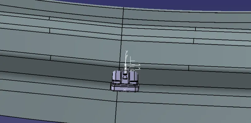
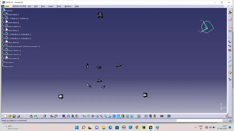
Overview of the connectors and clamps in the backdoor of the Car BIW part.
HARNESS ROUTING:
Routing Start with the Interconnection Connector point to the P-clamps in the workbench of Electrical Harness Assembly.
Click on Geometrical bundle command by convert to Electrcal Assembly.
After converted start routing with connectors.
Click Multibranchable start routing with connectors.
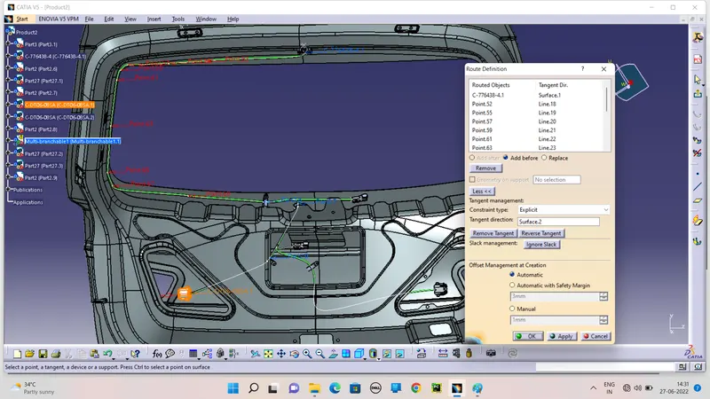
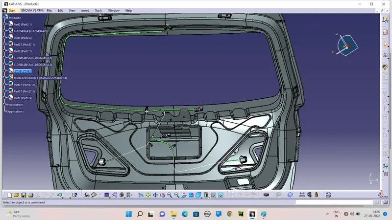
Likewise Routing all the wiring if needed place create the branch-point to multibundle creation.
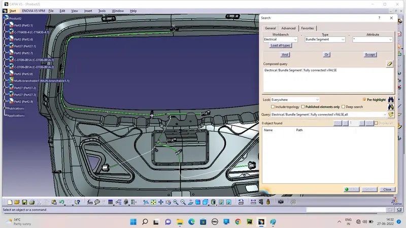
CHECK IF FULLY CONNECTOR:
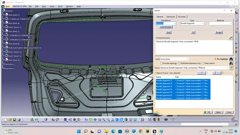
Check the bundle segment is fully connector or not before the Extract to Flatten.
Click (ctrl+f for search) button is open the Advance search option . Elctrical>Bundle Segment>fully connector
And check if True and False are both.
FLATTEN:
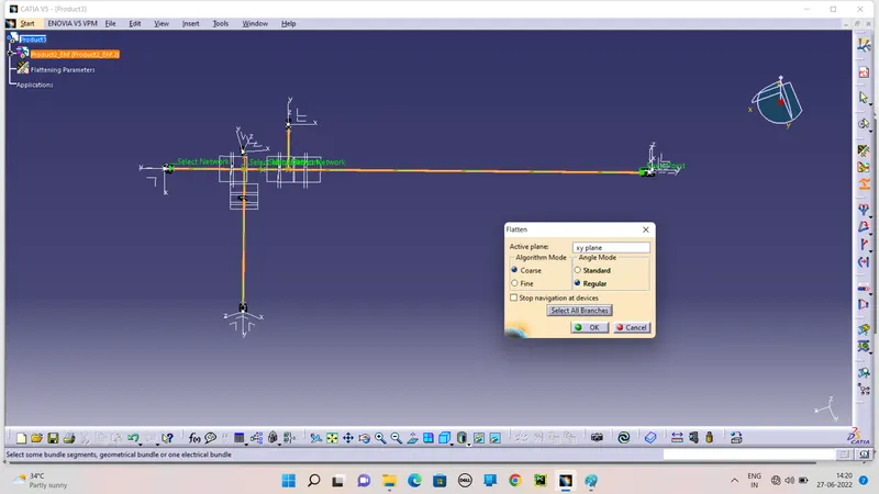
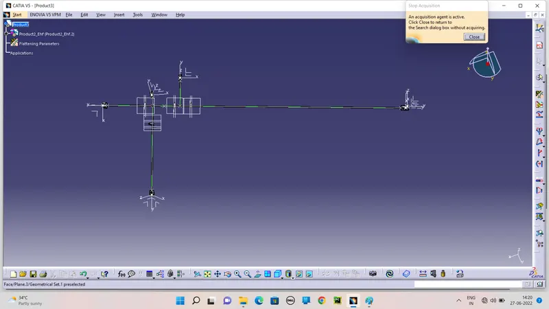
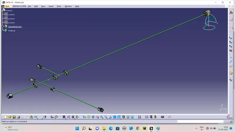
Geometrical Assembly Extraction to Flatten Assembly and Before Extraction to Switch the flattr=enin assembly and set flattening parameters.
After Extraction to Flatten the bunble segment by using flatten command.
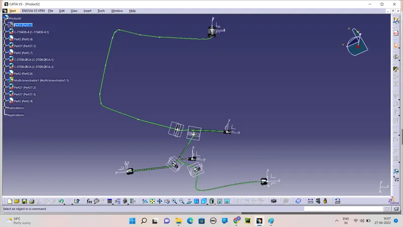
Select the front view of the routing and selection of fully bundle.
AFTER FLATTEN:
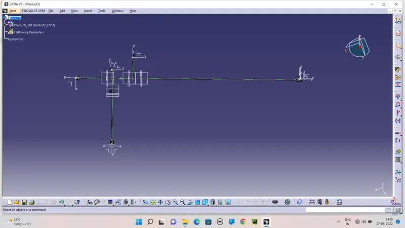
Hide the planes ans points and Axises of the flatten.
DRAWING:
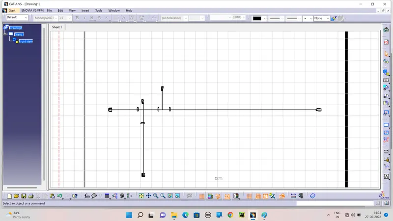
Open the new file of the Drawing and Add the front view of the Flatten and goes to Product select the oriantation of the views.
Loaded to Drawing sheet and the go to properties click the 3D wireframe is always.
CAD PART OF THE WIRING HARNESS: