Project 2 - 2D meshing on the instrumental Panel
AIM: To do a 2D meshing on the given instrumental Panel.
Objective:
- Geometry clean-up
- Middle mesh extraction
- Using align manager to define the features
- Quality check
- Assigning thickness
Description:
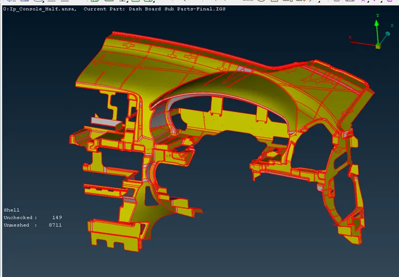
We have ANSA file as an input for this project. As we study the model, it will be very clear that it has varying cross sections, varying thickness, and different features. Generally, the plastic components are made in such a way as shown in following image to improve the strength of the component.
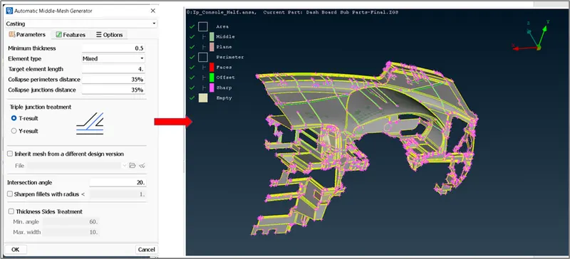
In this project, middle mesh is extracted by using casting method (Automatic middle mesh generator). This completely automatic function is used to create FE shell elements that represent the middle skin of a solid description. By using this option, ANSA tries to provide most appropriate middle mesh considering the available surfaces. Later, by using the Align manager option, the deviations in surfaces and perimeters are corrected.
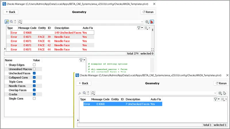
The first step is to check the geometry and do a quick clean-up.
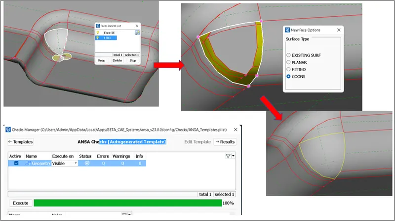
In most of the corners, the faces were not properly stitched, these areas are manually fixed as shown.
Now, by using the casting option in mid-surface, the middle mesh is extracted as shown.
TOPO>Faces>Mid.Surface> Casting
There are some deviations observed in the generated middle mesh, hence align manager option is used to correct them.
TOPO>Faces>Mid.Surface> Align Manager
This function creates several types of Alignment entities through which the correct position of Middle surface extraction entities can be handled. The Align entities can be manually created from the user or automatically at the end of the Casting Process.
Steps:
- The base of the component is checked first for any deviations and fixed. Mainly it was observed that the faces are wrongly picked during the mesh generation and hence causing some issues like warpage. These are rectified by using edit option in the type of area that is generated. The correct faces or planes can be edited and rectified inorder to generate the correct mid mesh.
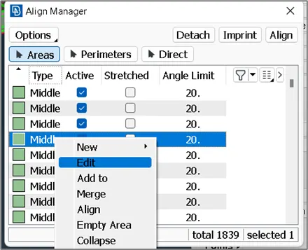
2. In the areas where the middle mesh is not generated properly due to variation in features, following process was done:
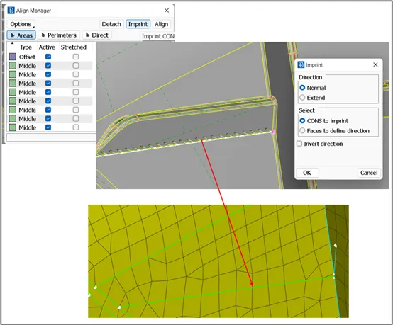
- Imprint the edges on the base middle mesh using “Align manager >Imprint” option
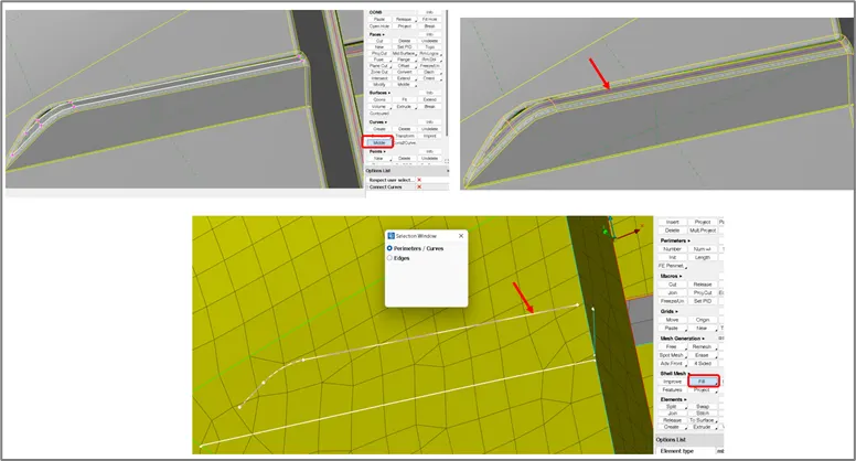
b. Create middle curve using TOPO>Curves>Middle on the ribs as shown.
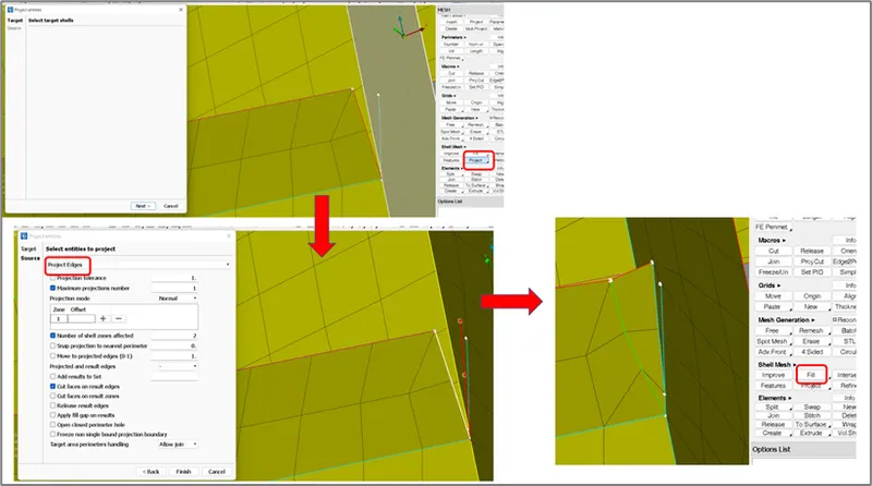
c. Fill the perimeter with mesh elements using MESH>Shell Mesh>Fill
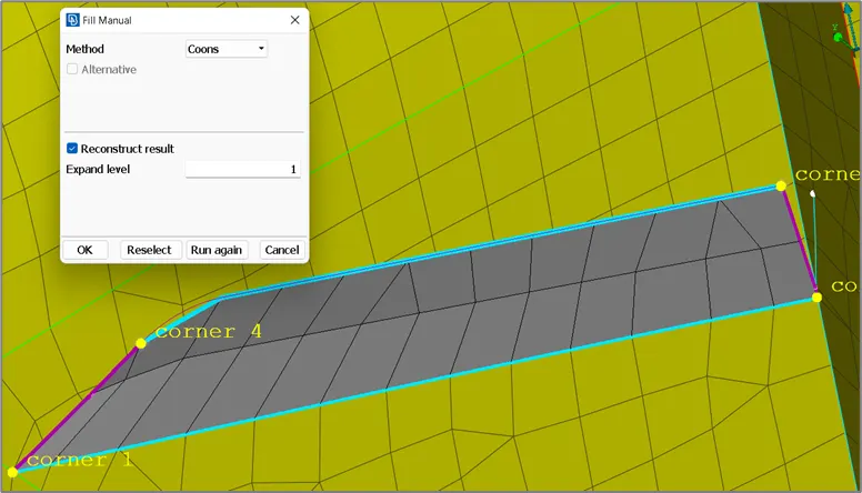
d. Project the edges on the near surface it is connected to it using MESH>Shell Mesh>Project
e. Again, use fill option to fill the elements to finally make it a proper middle mesh for that feature.
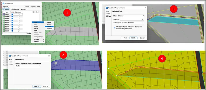
f. The definition of the newly created middle mesh needs to be defined by using Align manager as shown step -wise. The un-assigned area is highlighted in grey colour and the assigned area is highlighted in yellow colour depending on the type of definition that is used.
g. The perimeter of this mid-mesh is defined by using Align manager > Perimeter > select the cons>edit>assign the appropriate face.
3. Dog houses are generally not properly generated by using auto mid generator and hence manual method must be used to do the same. Similar commands as mentioned in step 2 are used to build the dog houses.
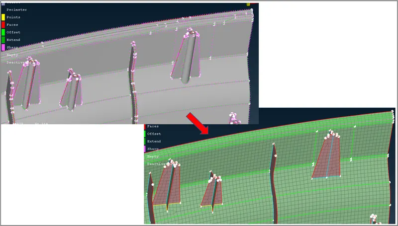
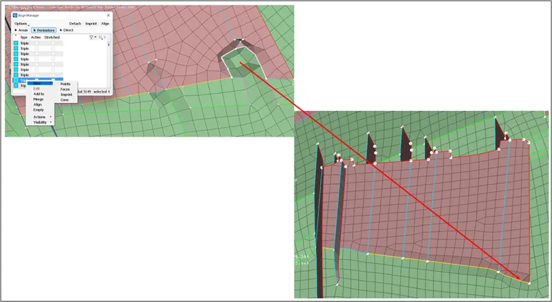
Generally, in the dog houses, we encounter that the base is not properly aligned as shown. This can be fixed by using Align manager>Perimeter>select the cons>New>Points>define 2 points and finish.
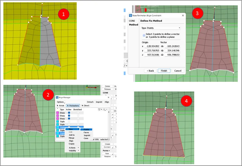
Similar fix is applied at all the dog houses, another example shown below:
4. Warpage issues that are not solved using previous methods, can be solved by following steps:
- Remove the unwanted hot points.
- Align manager > Detach > Detach the cons where there is an issue
- Stitch the area by using Paste command, so that the nodes are properly connected and there is a uniform mesh flow
- Join the cons wherever needed. In the options list we can set Align constraints as “Keep bigger.”
- Fill the area by using the Fill command.
In this way, the middle mesh with correct area and perimeter definition are created.
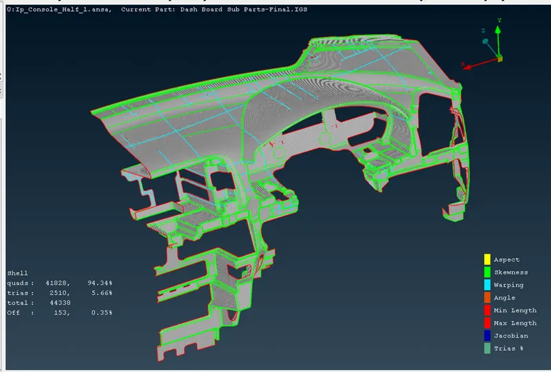
The next step is to provide the quality criteria and fix the quality errors.
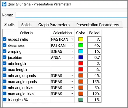
A lot of quality issues will be present due to the complex geometry, these needs to fixed step by step starting from any one of the side/areas. Try not to do a reconstruct on the aligned features as this may cause bringing the elements out of the original/aligned position.
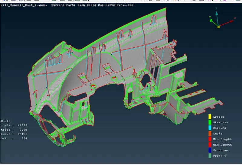
Different options under classic mesh are used to fix the quality. Most frequently used ones are:
- MESH>Elements>Split
- MESH>Shell Mesh>Improve
- MESH>Grids>Paste
- MESH>Elements>New
- MESH>Macros>Join
There are some of the areas which are too close and flimsy where the quality may not be corrected and hence left as is.
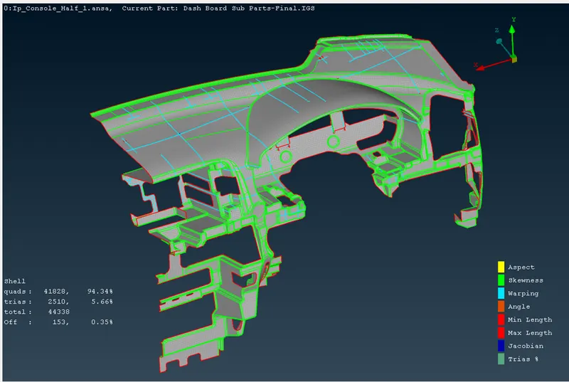
The mesh flow is then corrected to an extent by using the similar options as mentioned above.
Finally, the thickness of the individual feature is assigned by using TOPO>Faces>Set PID
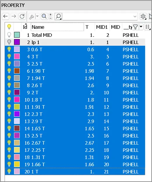
Draw shell as solid should is activated for representation purpose.
Learning outcomes:
Effective usage of Align manager option.
Conclusion:
Thus, the 2D meshing of the instrumental panel is done using auto-mid and align manager and the mesh quality is fixed.