Project 2
Aim and Objective:
To mesh the given cad model with the mentioned quality criteria and assigning thickness finally
Target Element Length = 5mm
| S.N | Quality Criteria | Value |
| 1 | Aspect Ratio | 5 |
| 2 | Skewness | 45 |
| 3 | Warping | 15 |
| 4 | Taper | 0.5 |
| 5 | Min. Length | 2mm |
| 6 | Max. Length | 8mm |
| 7 | Min angle Quad | 45 |
| 8 | Max angle Quad | 135 |
| 9 | Min angle Tria | 20 |
| 10 | Max angle Tria | 120 |
| 10 | Tria % | 10 |
Procedure:
- Open the .hm file using hypermesh, perform the geometry clean up whick includes replacing points, filler surface, toggle unnecessary edges etc., where we can find these options in the quick edit panel, Geometry- quick edit in the panel bar

- For creating midsurface of the component, go to distance in the geometry to find the distance for offseting the surfaces, go to geometry-surface edit-offset, enter the offset value,color normal should be blue, duplicate the surface before offsetting by making the newly created component as current component
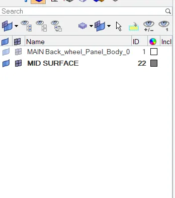


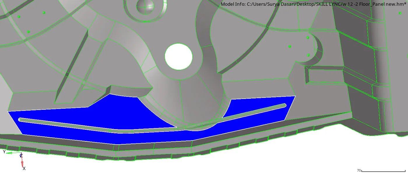
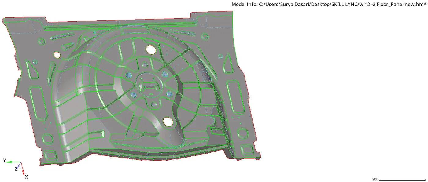
- FINAL MIDSURFACE MODEL
- For meshing go to 2D-automesh-select the surfaces-mesh, before that fill all the required quality parameters in the criteria file settings which is in the preferences option in main menu bar save the quality file, when we reopen the hypermesh we can directly select the quality file instead of filling each parameters
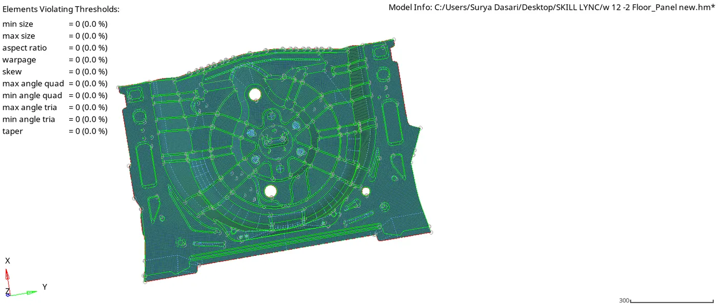
- Perform the mesh surface by surface by clearing all the errors which will be shown in the quality index or you can see by changing the view mode to quality


- Final QI MODEL
- For finding the free edges, go to tool-edges and find the edges after thst there will be a seperate collector created automatically in the component panel, select the tolerance value-preview to equiavalence the nodes, if still th free edges exists, go to 2D-replace-select the nodes



- MODEL WITH FREE OF EDGES
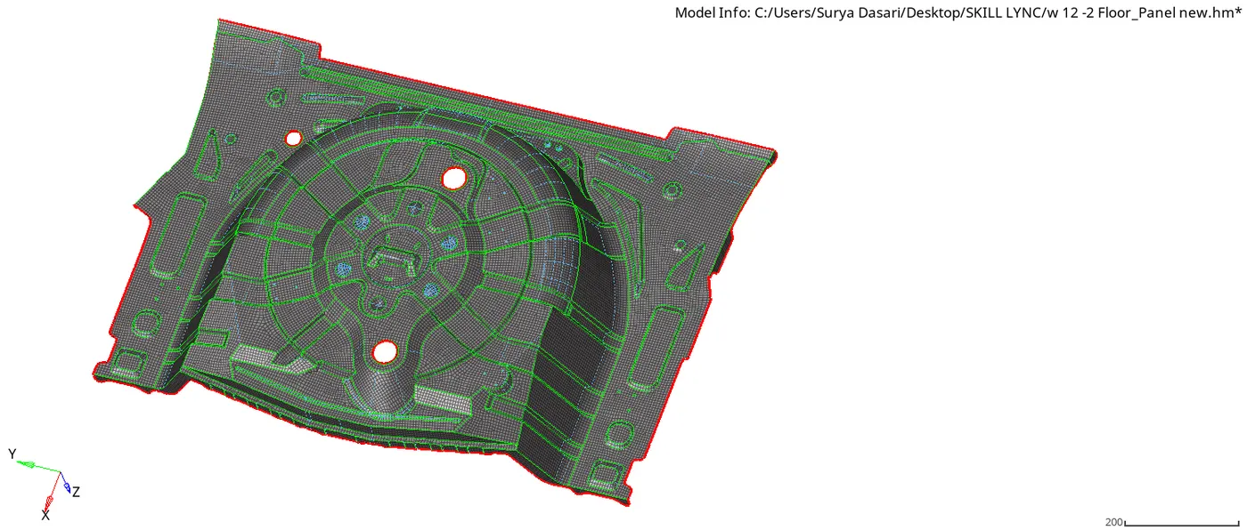
- We can go to element clean up option in the 2D panel to clean up the element
- While performing mesh follow the thumb rules which are mandatory
- For holes insert the washer spilt of 2mm
- For thickness right click on compnent panel-go to create-property- enter the thickness value and assign it to the midsurface component
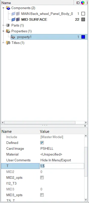
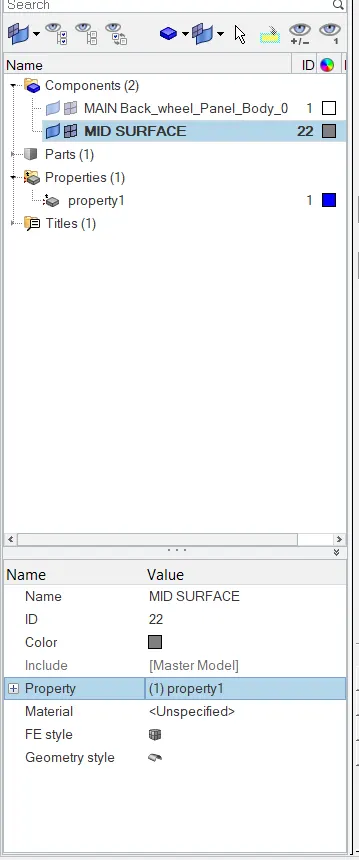
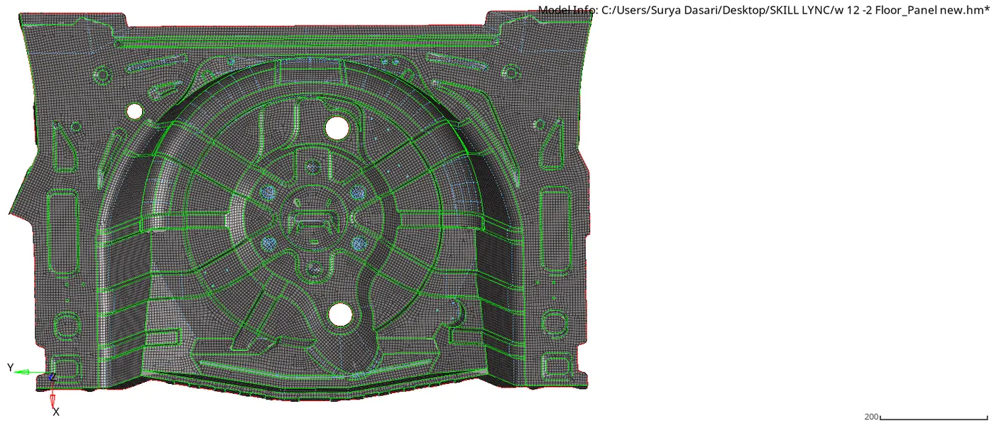
ABOVE FIGURE IS THE FINAL CAD MODEL with Thickness
Conclusion:
With the given project I have learnt how to perform the geometry cleanup, meshing and assigning thickness for the back wheel panel component
Note: .hm file and quality file are attached below