Project 2
- Design an interleaving DC/DC converter system for a data centre application with the following specifications:
- Input voltage: 45 – 60 v
• Output voltage: 3 V
• Output current: 100A
• Efficiency > 85% (extra credit for efficiency higher than 90% on a spice-based software simulation tool)
Simulate the system using a Spice-based software simulation tool such as LT-Spice, Pspice, PowerSim, TINA, etc...
Show your design in details (most probably, you will need to use an isolated system to achieve this low voltage conversion ratio, you might also need to use a multiphase system to increase the efficiency).
Show the input voltage, the output voltage, the input current, the output current, the system efficiency and any other simulation plots necessary to evaluate your design.
In Applications where nonisolation, step-down conversion ratio, and high output current with low ripple are required , an interleaved buck converter is been used.
The circuit diagram for interleaved buck converter is as shown :-
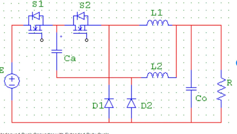
This interleaved buck converter has 3 modes of operation as shown in below figure :-
Mode 1:-
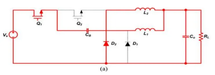
Mode 1 begins when Q1 is turned ON at t0 . Then, the current of L1 , iL 1 (t), flows through Q1 , CB , and L1 and the voltage of the coupling capacitor VC B is charged. The cur-rent of L2 , iL 2 (t), freewheels through D2 .
Mode 2:-
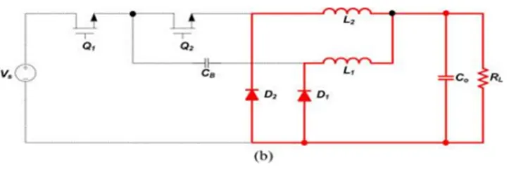
Mode 2 begins when Q1 is turned OFF at t1 . Then, iL 1 (t) and iL 2 (t) freewheel through D1 and D2 , respectively. Both VL 1 (t) and VL 2 (t) become the negative VO , and hence, iL 1 (t) and iL 2 (t) decrease linearly.
Mode 3:-
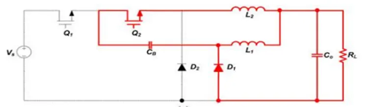
Mode 3 begins when Q2 is turned ON at t2 . At the same time, D2 is turned OFF. Then, iL 1 (t) freewheels through D1 and iL 2 (t) flows through D1 , CB , Q2 , and L2 . Thus, VCB is discharged.
Calculations:-
First , we will use the voltage ratio equ. To calculate the needed duty cycle:-
Vout/Vin=3/60
D=0.05
We know that the output voltage is 3v and they require 100A as output current
Therefore ,
P=0.3KW
P=300W
We can also determine that,
R=Vout^2/P
R=3^2/300
R=0.03 Ohm
Now, we will design the converter inductor:
We know that
`Il=Io=(P/Vo)=300/3=100A`
Then , let us design for 30% ripple in the inductor.
Then
`∆iL=0.3*100A=30A`
We know that ,
`L=((Vout)/(fs*∆Il))(1-D)`
`L=(3/(20k*30A))=0.95=4.75 uH`
Then l=4.75 uH
Let us now design the output capacitor
`Cout=((1-D))/(8*L*fs^2*(∆Vo/Vo))`
`Cout=0.95/(8*4.75uH*20k^2*(0.03))=2.08mF`
First the model was been designed in MATLAB Simulink the model in the Simulink is as shown below :-
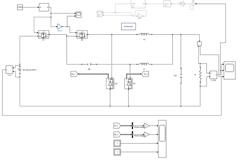
The input voltage is set to 60V with the help DC voltage source block. Here two mosfets are connected in series. The inductor L1 and L2 are of same rating , the values of the inductor is 4.75uH for both.
The capacitor CO is of 2.08mF and the resistor load connected is of 0.03ohm.
The frequency is set to 20KHz.
Result Scope :-
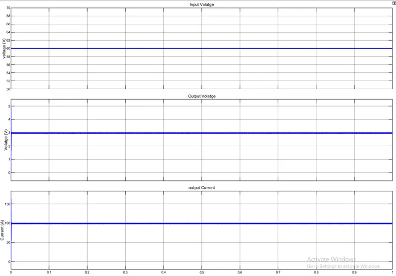
The above scope shows the input voltage , output voltage and output current.
The input voltage is 60V and the out pit voltage which we are getting is near to 3V and the output current is near about 100A as per the project challenge we are able to get the required outputs.
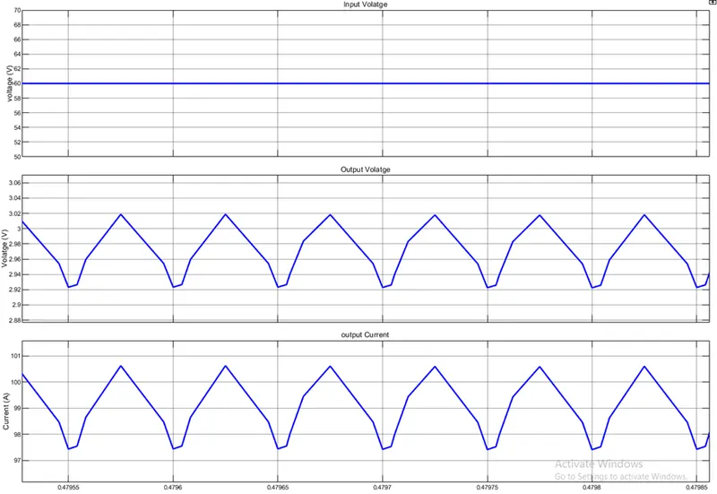
Zoomed in Scope:-
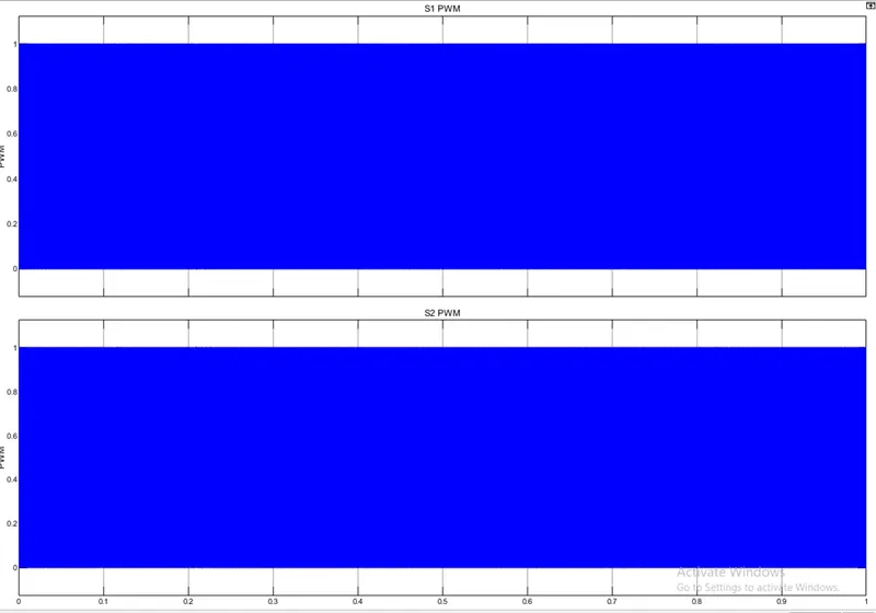
Scope 2:-
Scope 2 shows the PWM signal for mosfet S1 and S2.
Zoomed in Scope :-
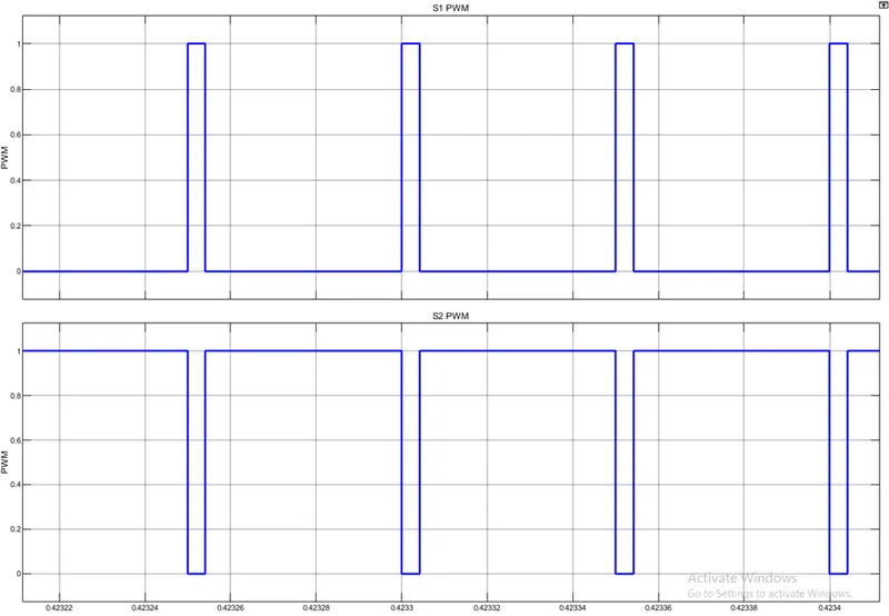
From the above scope we can see that when S1 is ON at that time S2 is OFF and vise -versa.
Scope 3:-
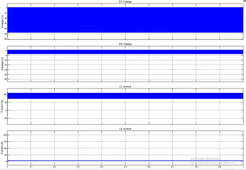
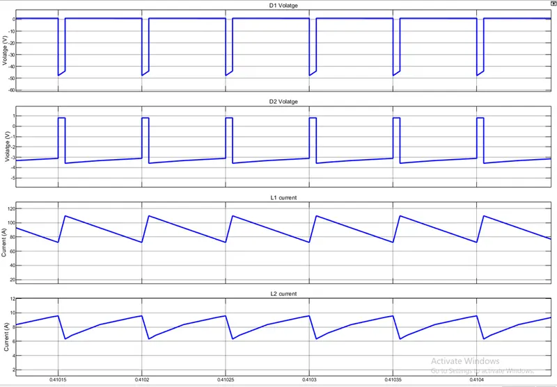
The above scope shows the voltage in diode D1 and D2 and the current in Inductor L1 and L2.
zoomed in scope:-