Project 2
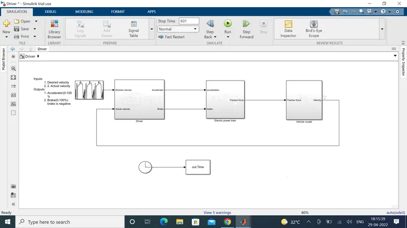
The main blocks of the model is shown above which consists of
1. Driver block
2. Electric power train block
3. Vehicle model
1. Driver block
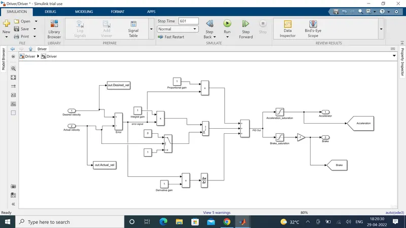
Based on the desired velocity and actual velocity the driver block gives acceleration and brake output. This block uses a PID controller to produce the desired output. The technique is shown below
2. Electric power train block.
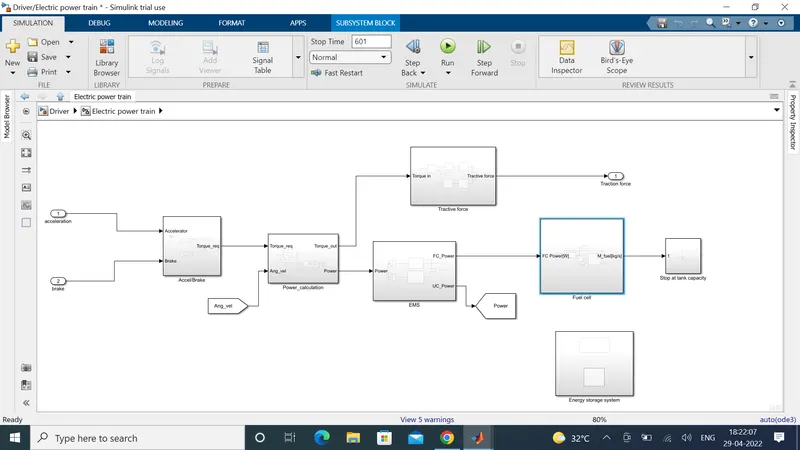
The electric power train subsystem consists of
1. Accel/Brake block to calculate required torque
2. Power calculation to calculate torque output and power
3. Tractive force to calculate traction force
4. EMS to calculate fuel cell power and ultracapacitor power
5. Fuel cell to calculate stack voltage, stack current and fuel requirement
6. Energy storage system to give the output of stored energy in ultracapacitor
3. Vehicle model
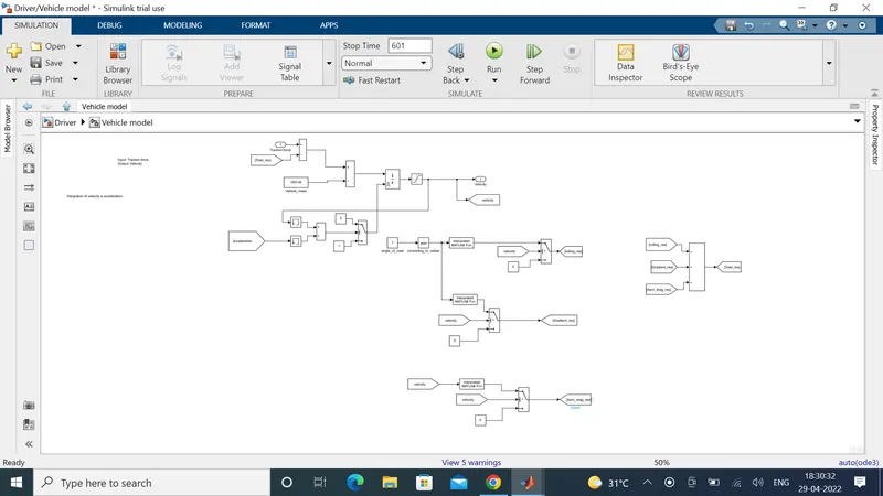
This model calculates the required resistance of the vehicle in the road.
The fuel cell model of the vehicle is shown below
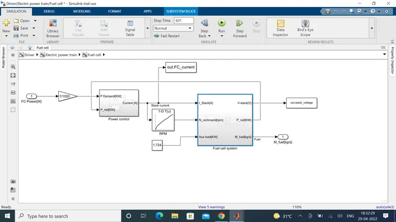
The power control system calculates the current required to feed to the fuel cell stack.
The fuel cell system subsystem contains compressor model and fuel cell stack block
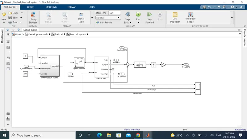
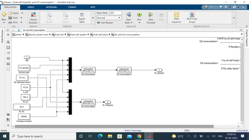
The fuel cell stack contains two subsystems shown below
1. Stack voltage block to calculate stack voltage and power
2. Air and H2 consumption to calculate the requirement of air and hydrogen
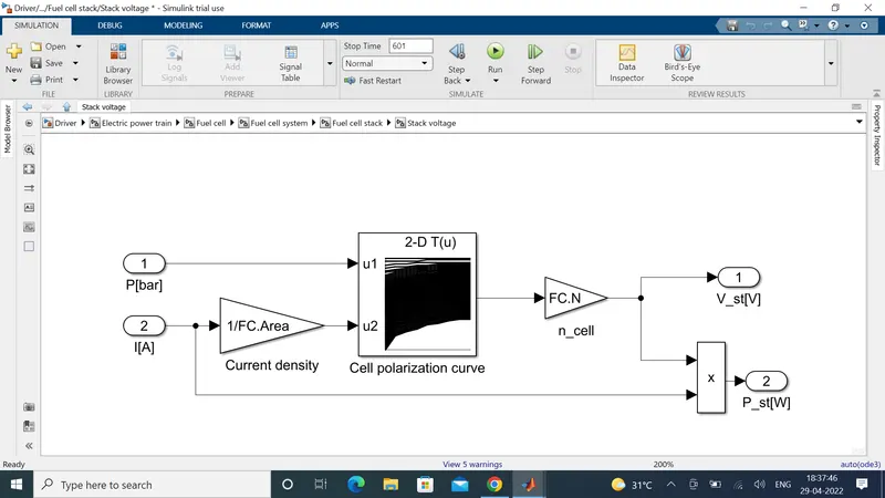
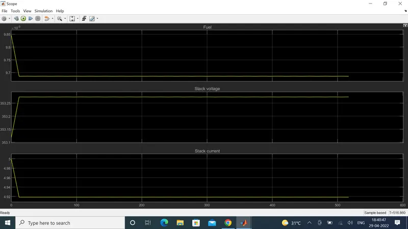
The output of the model is shown below