Project 2
AIM & INTRODUCTION:
To calculate the water current forces ,centrifugal forces, wave forces, snow loads, temperature loads, Barge Impact load for the bridge structure.
Water Current Force:
GIVEN DATA:
- The high flood level is 4m above the foundation level.
- The span of the bridge is 40m.
- The mean velocity of the river is 2.5 m/s.
Water Current Forces:
An ocean current is a continuous, directed movement of sea water generated by a number of forces acting upon the water, including wind, the Coriolis effect, breaking waves, cabbeling, and temperature and salinity differences.
PROCEDURE:
To calculate the Water Current Forces;
Mean Velocity,Vmean=2.5m/s
Max.Velocity,V=√2*Vmean
=√2*2.5
=3.53m/s
Water Current,P=52*K*V^2
I have assumed the pier is Square, therefore K=1.5
=52*1.5*3.53^2
∴Water Current,P=975KN/m^2.
Centrifugal Force:
GIVEN DATA:
- The span of the bridge is 40 m.
- Width of carriage way is 9 m.
- The bridge is subjected to a live load of Class 70R tracked vehicle.
- The design speed of the vehicles is 50 km/hr.
- The radius of curvature in the bridge is 2 m.
CENTRIFUGAL FORCE:
The moving of a vehicle in a curve produces an outward pushing force from the bridge which exerts loads on the structural elements of the bridge called as the Centrifugal Force.
Calculation of Centrifugal Force:
Design Speed,V=50KM/hr
Radius of Curvature,R=2m
Live Load,W=70KN
Centrifugal Force=W*V^2/127R
=70*(50)^2/127*2
Centrifugal Force =688.976378KN.
Wave Loads:
Wave Load:
*Waves are caused by a disturbance of the water surface.
*They develop due to disturbances like winds,boat, ship wakes or other forces such as underwater landslides due to earthquakes.
*When the wind blows on the sea , waves occur according to the intensity of the wind and generate a force on the any bridge substructure like piers and abutments.
*This accounted as wave loads in the design of substructure for designing bridges in the sea.
Given Data:
*Maximum Crest , ηmax=3m
*I Girder,
Height of Girder=1.6m
Top Flange=2m
Bottom Flange=2m
Thickness of Flange and Web=0.3m
*Span of the bridge=40m
*Width of Span=10.5m
*Thickness of Deck Slab=1.5m.
*Assume constant Cr=0.4
*Assume Cva=3
*Storm Elevation=8.5m.
Calculations:
Δzh=ηmax-Centroid of I girder
=3-(1.6/2)
Δzh=2.2m.
Δzv=ηmax-Elevation of Bottom Deck
=3-1
Δzv=2m.
No.of Girders supporting Bridge deck,N=4
Vertical Loads, Fv=r*Δzv*Av
=5*2*(10.5*(1.6/2))
Vertical Loads, Fv=84KN
Horizontal Loads,Fh=r*Δzh*Ah
=5*2.2*(40*3)
Horizontal Loads,Fh =1320KN
Max Vertical Loads,Fmax=Cva*Fv
=3*84
Max Vertical Loads,Fmax=252KN
Max Horizontal Loads,Fh=(1+Cr(N-1))*Cva*Fh
=[1+0.4*(4-1)]*3*1320
Max Horizontal Loads,Fh=8712KN.
Snow Load:
Snow Load:
* Bridge structures are subjected to snow load when is the bridge is located in a snowy region or cold climate countries.
* The snow load is calculated as per IS 875 Part IV and loads are applied in accordance with IRC 6.
* The minimum snow load considered for design of bridge is 900Kg/m^3 as per clause 224 IRC 6.
PROCEDURE:
Calculations:
*Density of Settled Snow =3KN/m^3.
*Depth of Snow=1.25m.
*Flat deck, angle β=0 Degree.
* Span of the Bridge=40m.
*Snow Load ,So=Density of Settled Snow *Depth of Snow*Span of the Bridge.
=3*1.25*40
So=150KN/m.
Shape Coefficient from IS 875 Part IV,
For angle β<30 degree,μ=0.8
Design snow load,S=μ*So
=0.8*150
S=120KN/m.
Temperature Load:
- The Span of the bridge is 40 m.
- The diameter of the pier is 1.5m*1.5m
- The width of Deck slab is 10.5m.
- The Thickness of Deck slab is 1.5m.
Temperature Loads:
Assume Chennai
Daily and seasonal fluctuations in shade air temperature solar reduction etc cause the following.
- Effective bridge temperature changes in overall temperature of bridge.
- After a period , there will be a minimum and maximum with a range of effective bridge temperature.
- This results in loads or load effect.
The loads effects are due to
- Temperature restraint - Restraint offered for expansion or contraction by form of constructions.
eg. Portal frame ,arch,flexible pier,elastomeric bearings etc.
- Frictional bearing restraint - Friction at roller or sliding bearings.
Temperature difference - Difference in temperature between the top surface and other levels through the entire height of superstructure.
Calculations:
* Max temperature in the location as per IRC 6 Isotherm at the location=45°
* Min temperature in the location as per IRC 6 Isotherm at the location=12.5°
* Effective Temperature Difference=(45-(12.5))/2+10
Effective Temperature Difference=26.25°
* Stess due to temperature =α *ΔT*E
=11.27*10^-6*26.25*5000(40)^(1/2)
Stess due to temperature =9.35KN/m^2.
Barge Impact:
* Span of the Bridge =40m
* Width of the bridge =10.5m
* Piers of size 1.5 m x 1.5m
* The Rise of the bridge = 5m
* The Deck slab is 500mm thick
* The cross Girders are 0.75 m x 1.8 m
* Hydrodynamic coefficient(CH)= 1.25.
*W=52500 DWT.
* Speed of the Barge(V) = 60Km/hr.
PROCEDURE:
Calculations;
*Barge Collision Energy, KE=500*CH*W*V^2
where,
Hydrodynamic coefficient(CH)= 1.25.
W=52500 DWT.
V = 60Km/hr.=16.6667m/s
KE=500*1.25*5.2500*(16.667)^2
KE=911822.9531 N-M.
* Barge Damage depth,aB
aB=3100*([1+1.3*10^-7*KE]^0.5-1)
=3100*([1+1.3*10^-7*911822.9531 ]^0.5-1)
Barge Damage depth,aB=178.5881741mm
* Barge collision impact force,PB
For aB≥100mm,pB=6*10^6+1600*aB
=6*10^6+1600*(178.5881741m)
pB=6285741.079N.
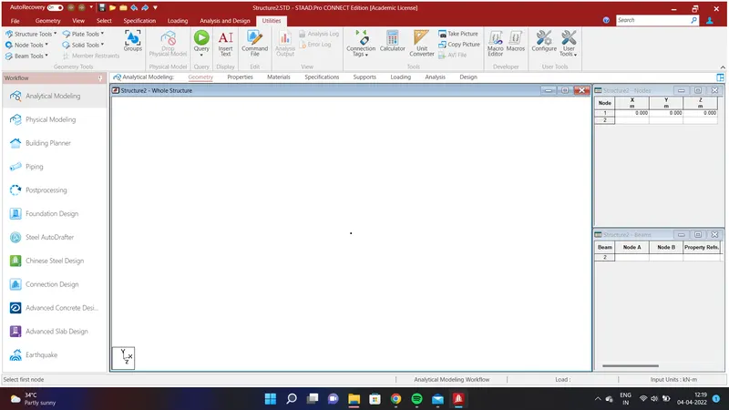
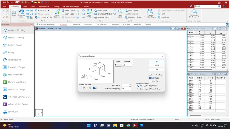
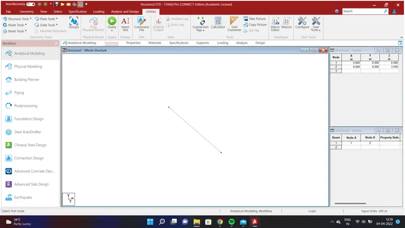
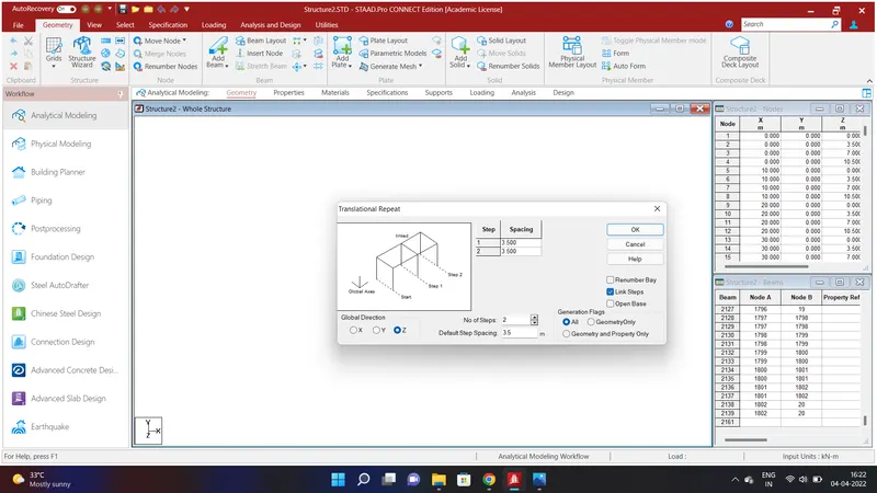
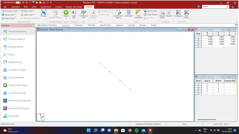
Create a node by assigning values od Node 1 as X=0;Y=0;Z=0 . Select the node using node cursor in the select option and go to Geometry Option and select Translational Repeat in Z Direction and assign the values as No. of Steps=1;Default Step Spacing=3.5m and Link Steps and Click OK. We shall have created a beam of width 3.5m. Again select the beam and go to Geometry Option and select Translational Repeat in Z Direction and assign the values as No. of Steps=2;Default Step Spacing=3.5m and Link Steps and Click OK. We shall have created a beam of width 10.5m.
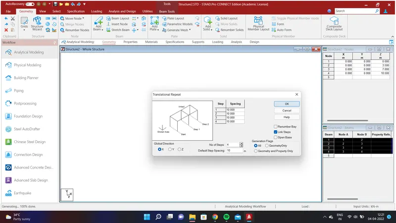
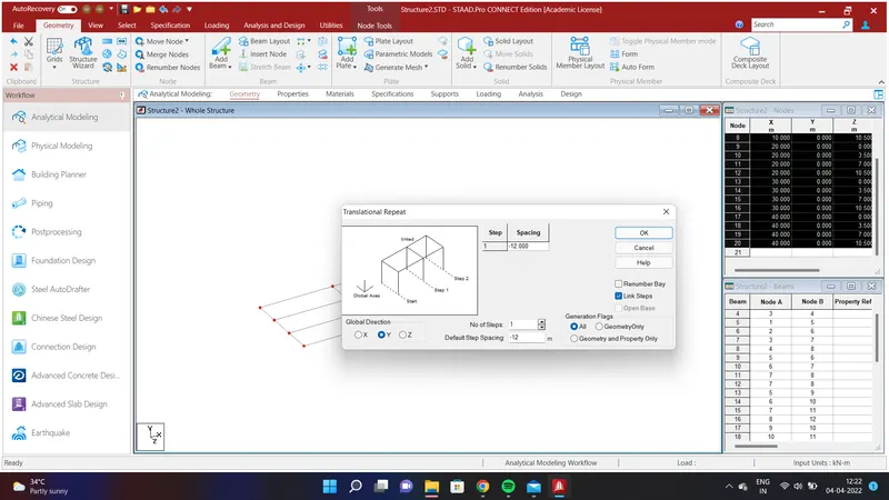
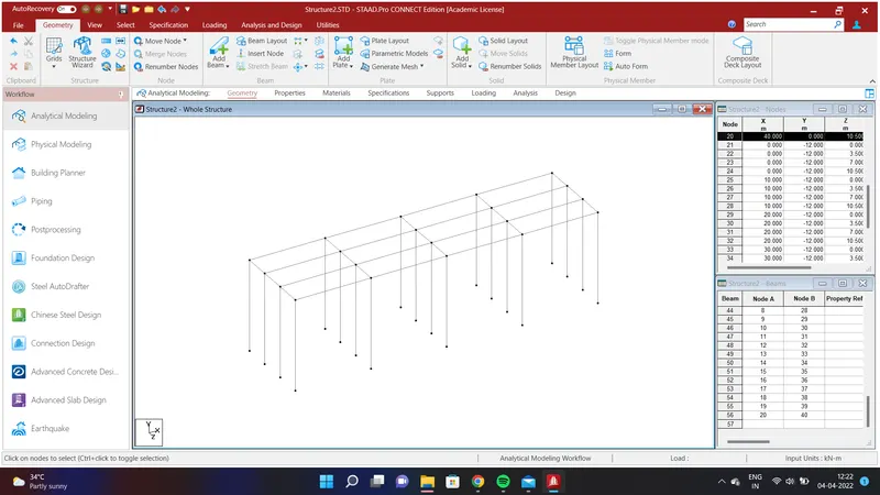
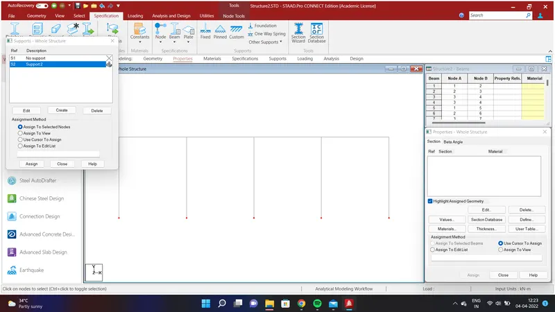
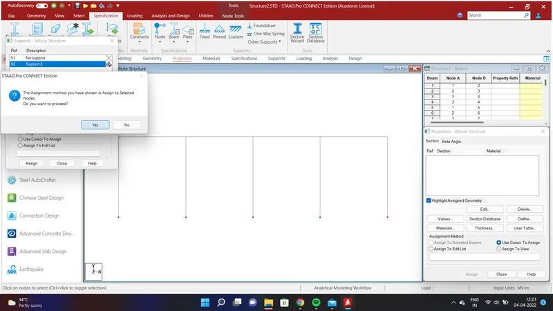
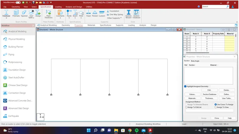
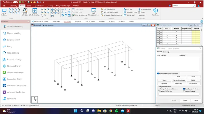
We shall create the span of length 40m. To do that go to Geometry Option and select Translational Repeat in X Direction and assign the values as No. of Steps=4;Default Step Spacing=10m and Link Steps and Click OK. We shall have created a bridge structure. We shall create piers to the bridge structure. To do that select all the node in the bridge using node cursor in the select option and go to Geometry Option and select Translational Repeat in Y Direction and assign the values as No. of Steps=1;Default Step Spacing=-12m and Link Steps and Click OK. We shall have created a pier of height 12m as mentioned in the above problem. To provide fixed support to the piers go to select option and select the node cursor and select all the pier bottom nodes and go to Specification Option and select Fixed and click Add and select Support 2 and select the bottom pier nodes and click Assign to Selected Nodes and click Assign and YES. We shall have provided fixed support to the piers.
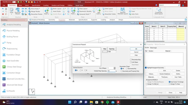
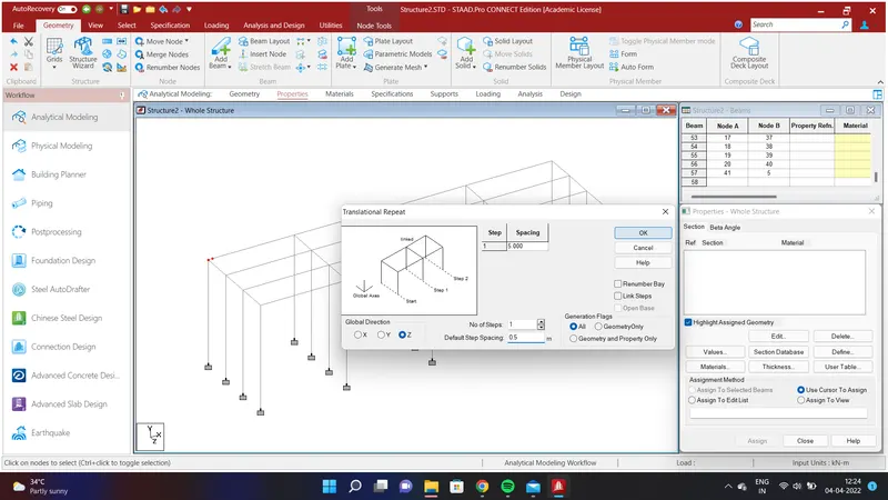
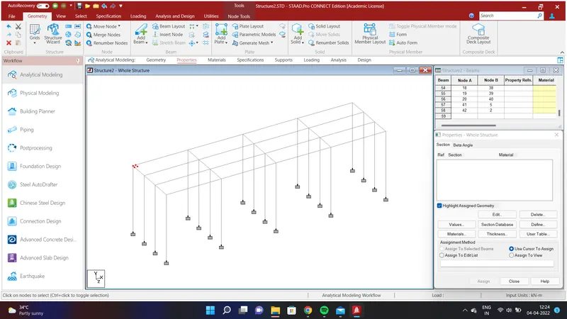
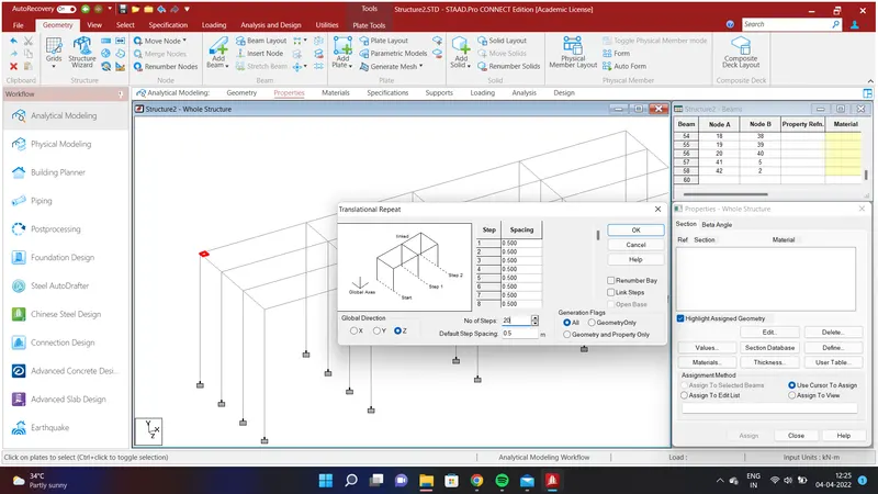
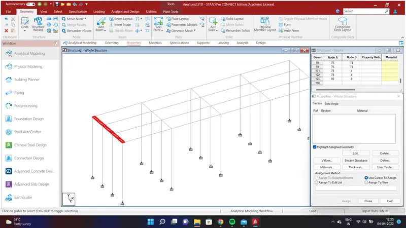
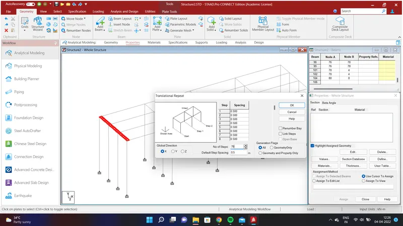
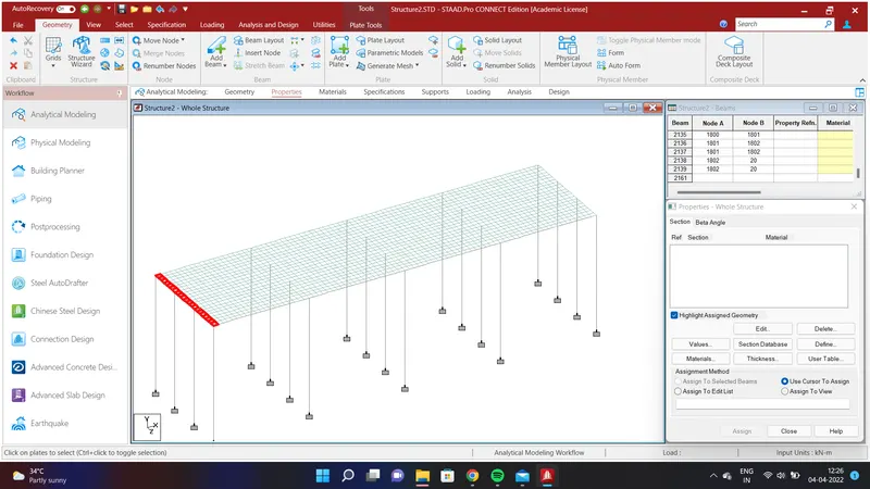
We shall create a Deck Slab to the bridge structure. To do that go to select option and select Node cursor and go to Geometry Option and select Translational Repeat in X Direction and assign the values as No. of Steps=1;Default Step Spacing=0.5m and Click OK. Again select the nodes and go to Geometry Option and select Translational Repeat in Z Direction and assign the values as No. of Steps=1;Default Step Spacing=0.5m and Click OK. Create a plate using Add plate option and select plate cursor in the select Option. Again select the plates and go to Geometry Option and select Translational Repeat in Z Direction and assign the values as No. of Steps=20;Default Step Spacing=0.5m and Click OK. Again select all the plates and go to Geometry Option and select Translational Repeat in X Direction and assign the values as No. of Steps=79;Default Step Spacing=0.5m and Click OK. We shall have created Deck Slab throughout the bridge.
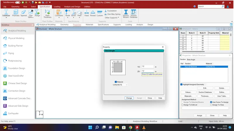
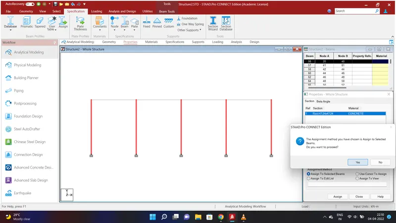
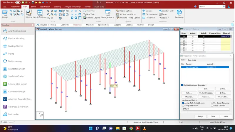
We shall assign properties to the piers . To do that go to Specification Option and select Prismatic and go to Rectangle assign the values of YD=1.2m;ZD=1.2m using Concrete Material and click Add. Select all the piers and click Assign to Selected Beams and click Assign and click YES. Properties to the piers will be assigned.
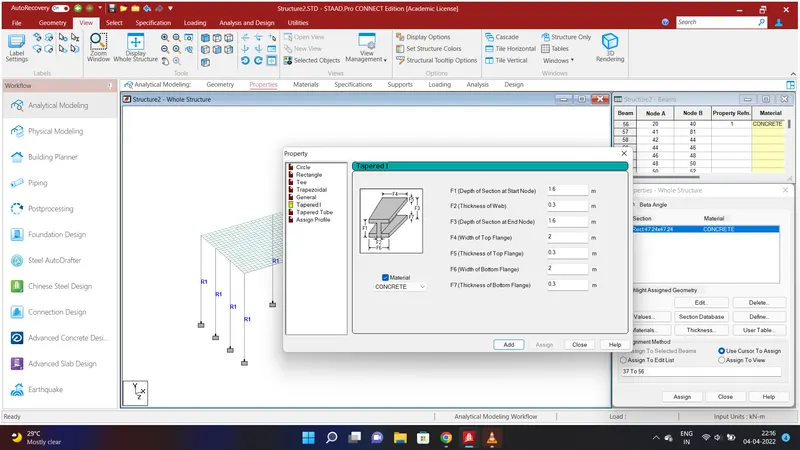
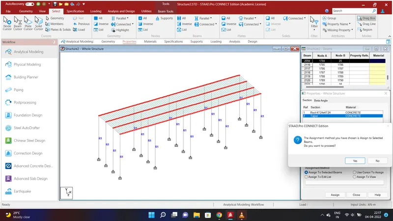
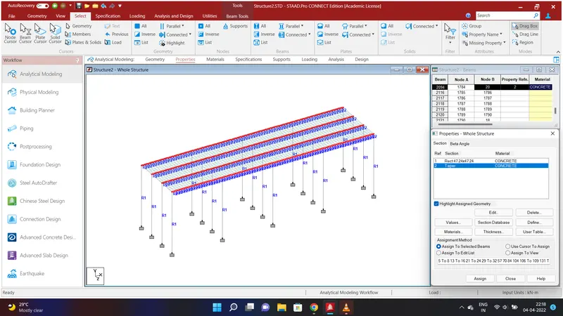
We shall assign properties to the Girders. To do that go to Specification Option and select Prismatic and go to Tapered I and assign the values ofF1=1.6m;F2=0.3m;F3=1.6m;F4=2m;F5=0.3m;F6=2m;F7=0.3m using Concrete Material and click Add. Select all the Girders and click Assign to Selected Beams and click Assign and click YES. Properties to the girders will be assigned.
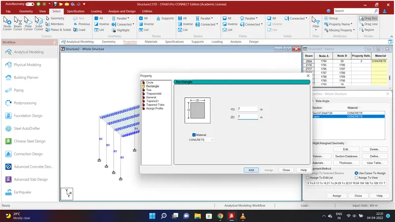
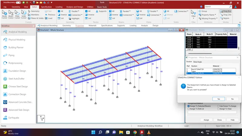
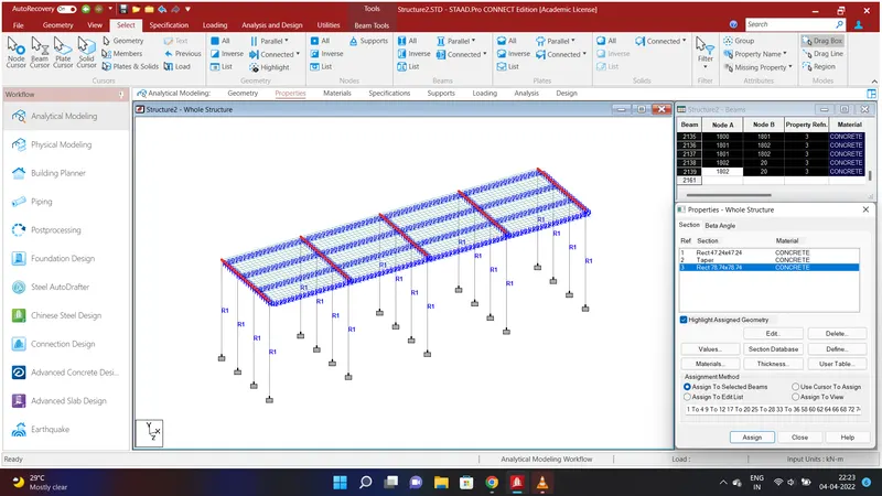
We shall assign properties to the Crossbeams . To do that go to Specification Option and select Prismatic and go to Rectangle assign the values of YD=2m;ZD=2m using Concrete Material and click Add. Select all the Crossbeams and click Assign to Selected Beams and click Assign and click YES. Properties to the Crossbeams will be assigned.
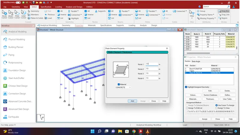
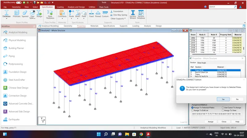
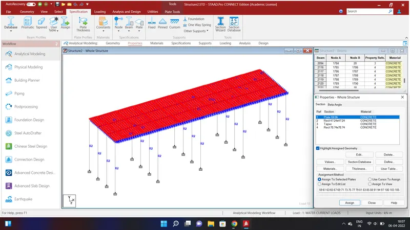
We shall provide deck slab of thickness 1.5m as mentioned in the above problem. To do that go to Specification Option and select Plate Thickness and assign the values as follows Node 1 =1.5m;Node 2 =1.5m;Node 3 =1.5m;Node 4 =1.5m using Concrete Material and click Add . Now go to select option and select plate cursor and select all the plates and clcik Assign to Selected Plates and Assign and click YES. We have assigned all the properties to the structure.
RESULT:
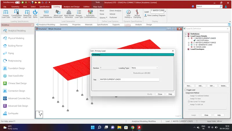
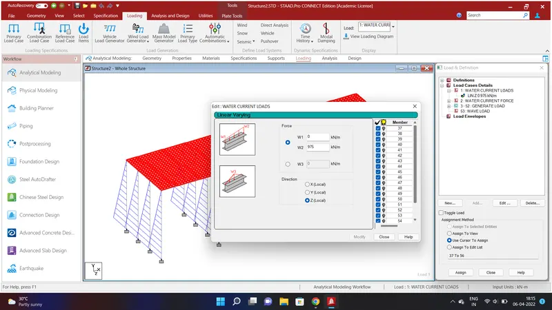
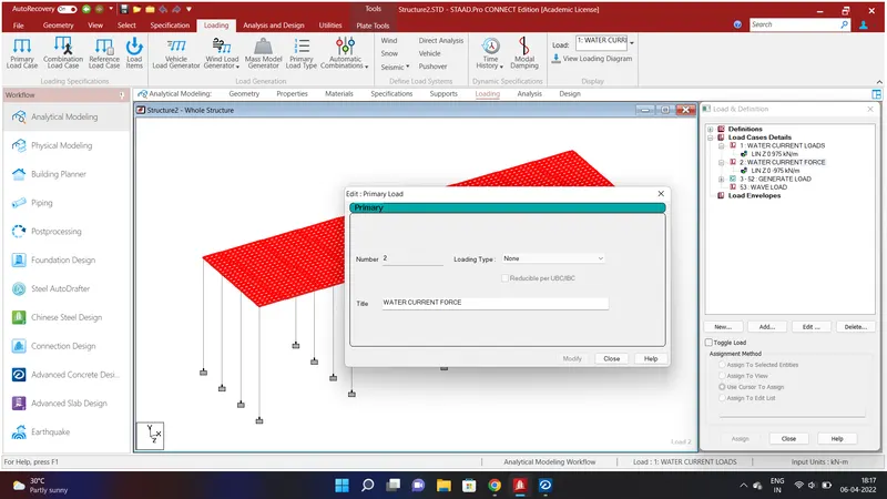
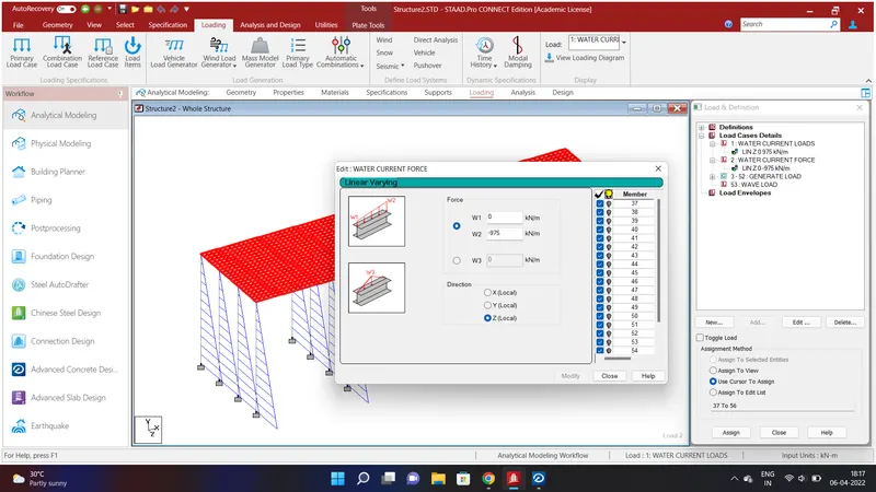
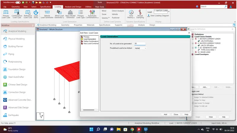
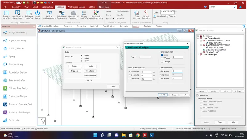
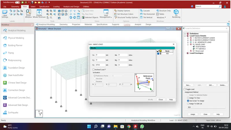
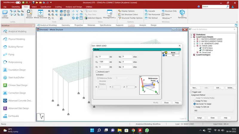
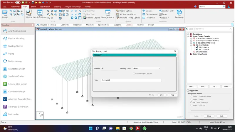
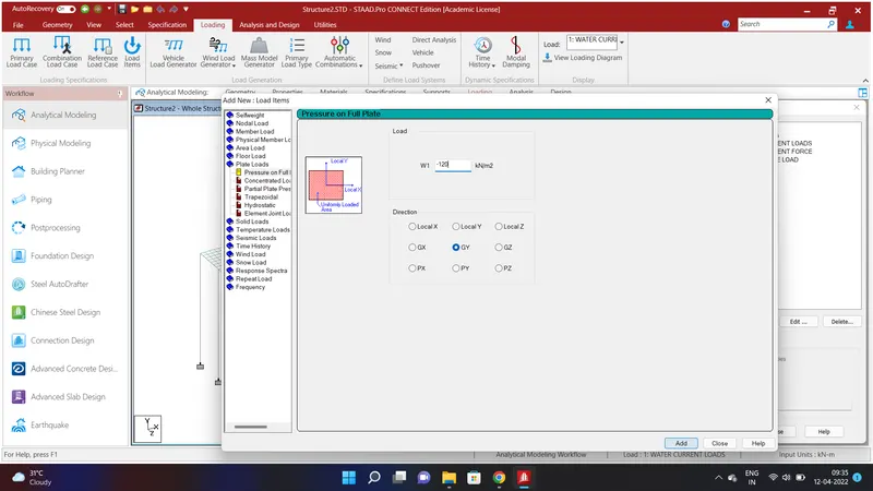
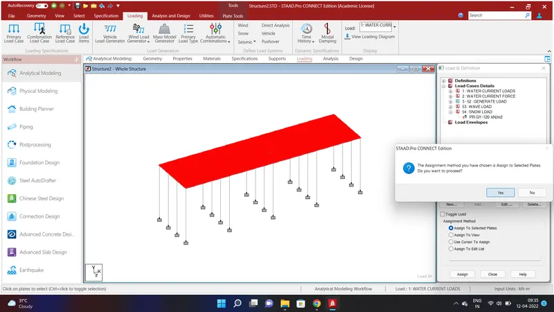
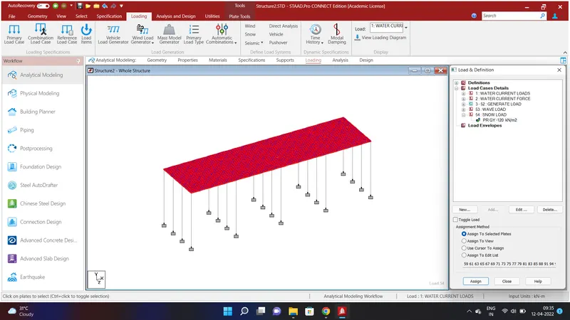
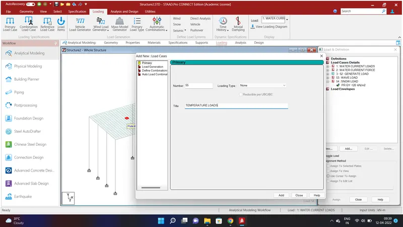
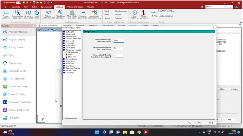
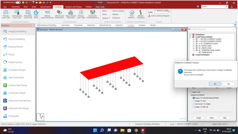
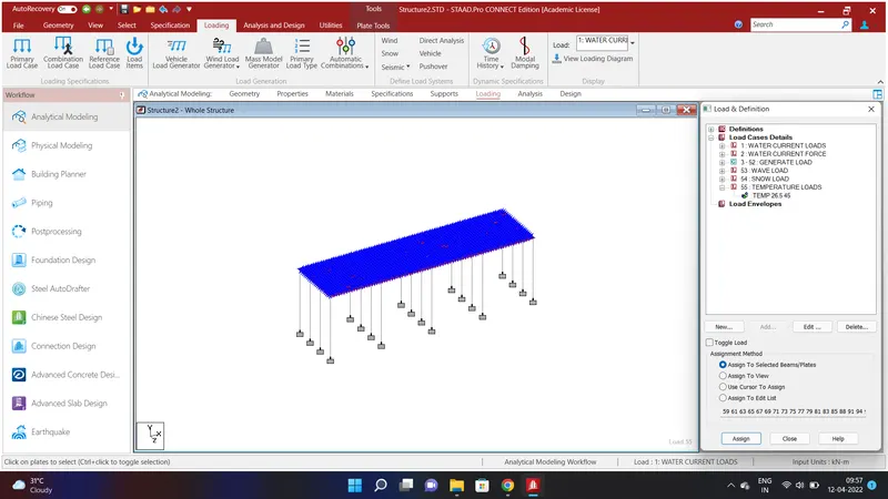
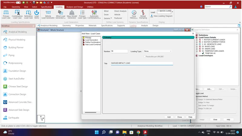
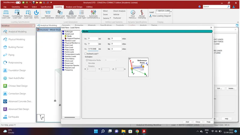
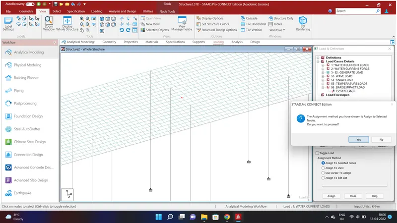
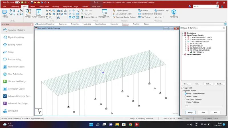
We shall have assignes to the following:
* Water Current Forces
* Centrifugal Force
* Wave Load
* Snow Load
* Temperature Load
* Barge Load.
REPORT:
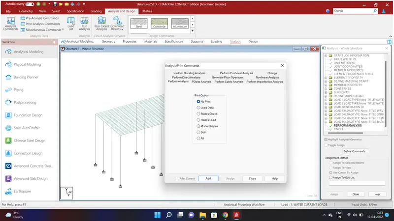
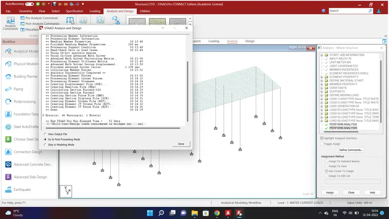
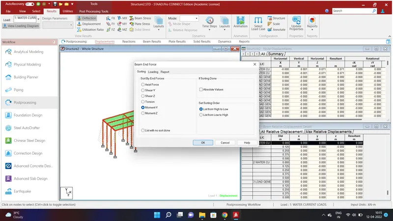
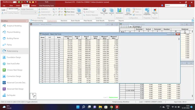
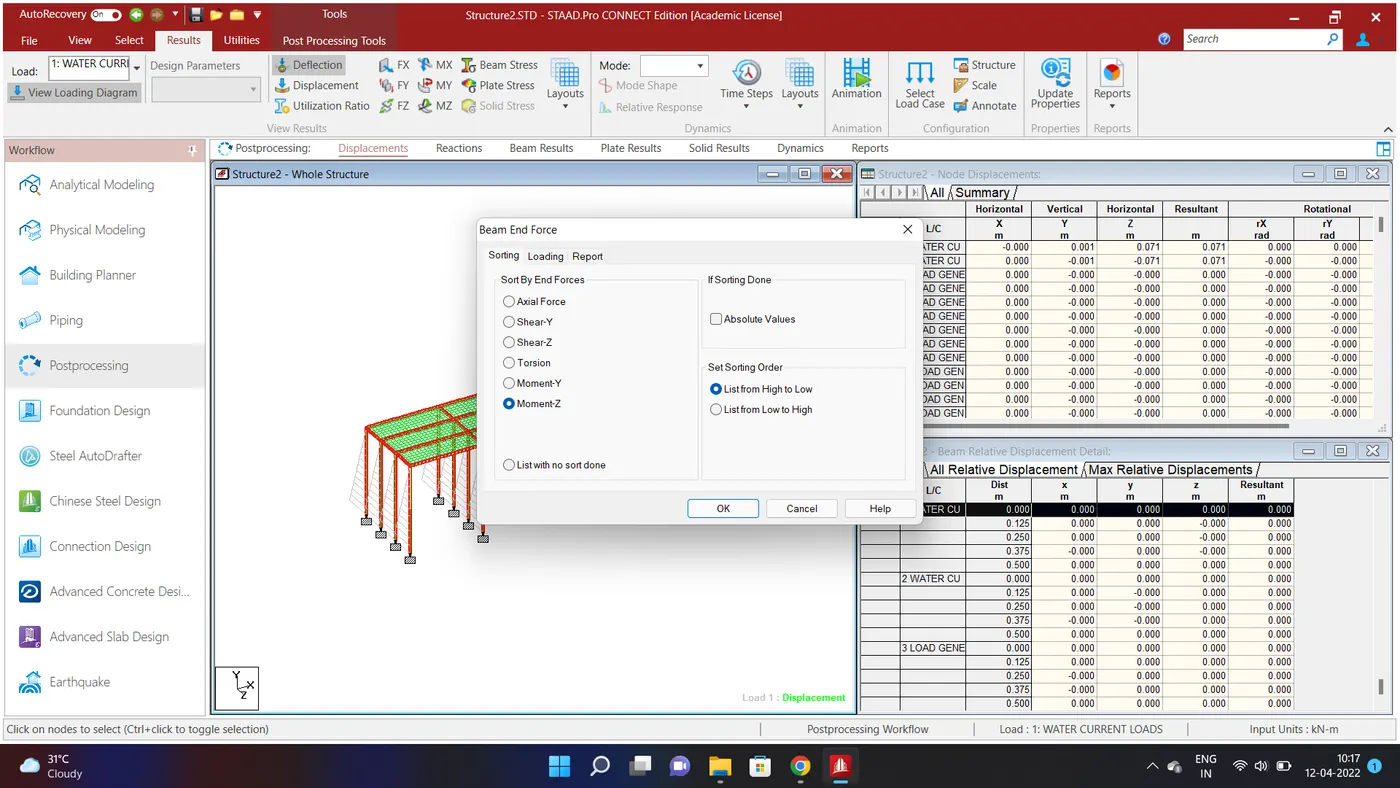
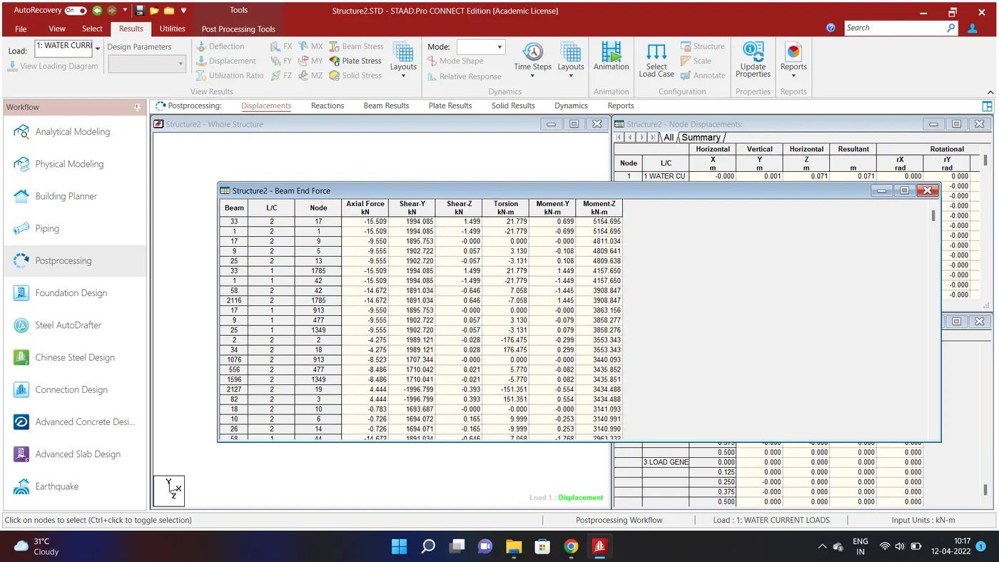
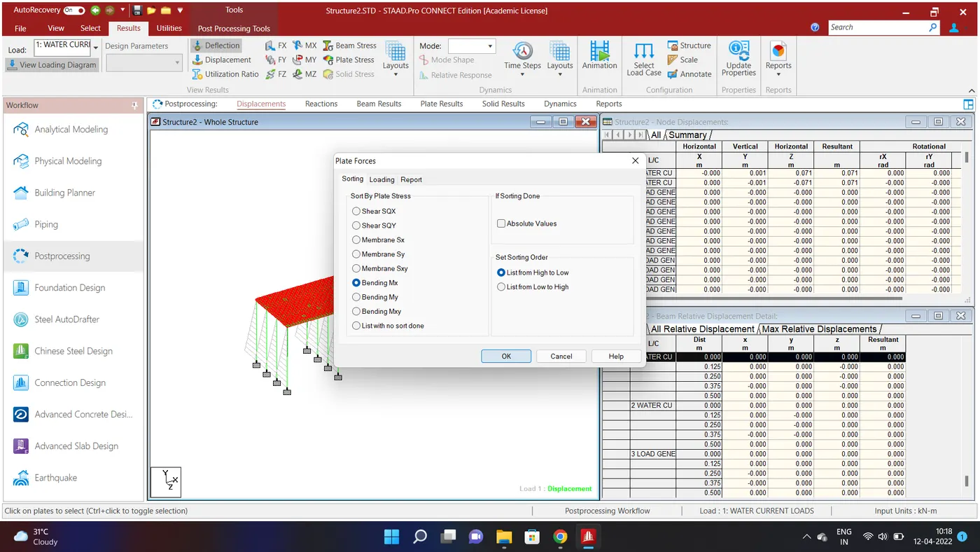
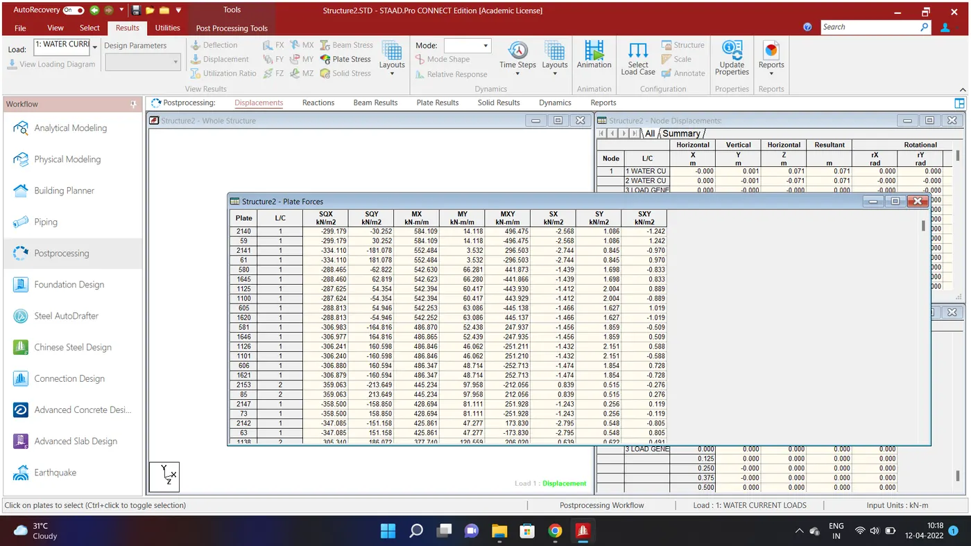
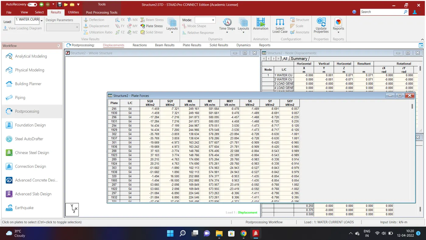
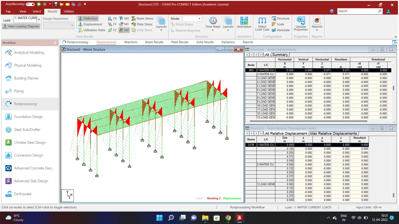
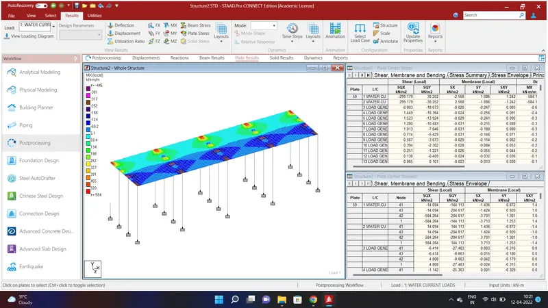
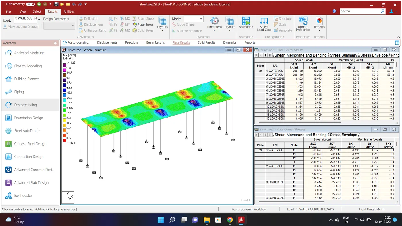
We have obtained report for the following forces and results are shown mentioned in the staad.pro.