Project 2
AIM:
the aim of this project is to create routing for the Tail Gate for the two tail lamps and also Number plate for lights. and also to create Flatten for the bundle segments.
Steps involved to create routing:
Download the Mechanical parts like connectors and suppourt devices and apply electrical properties
Defining the mechanical parts as Electrical parts by providing electrical properties:
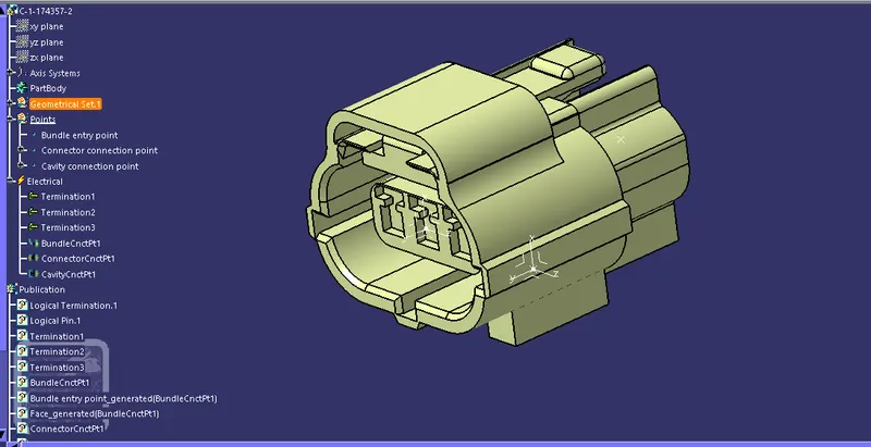
3 POLE CONNECTOR:
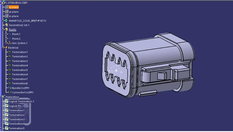
8POLE CONNECTOR:
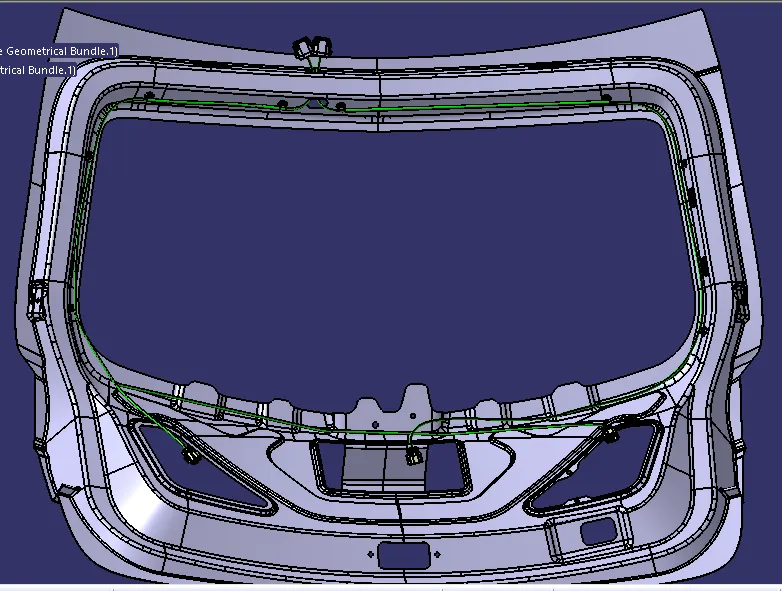
PROCEDURE FOR CREATING ASSEMBLY CONTEXT AND GEOMETRICAL BUNDLES:
- open a Assembly design work bench and add components like Tail gate, connectors and suppourt devices.
- arrange the connectors and fir tree clips in required places in a saperate folder of existing components.
- Create a geometric bundle and then the multi branchable segment is created.
- create bundle segments by using bundle segment defnitions in required positions by connecting the required connectors.
IMAGES OF INDIVIDUAL GEOMETRIC BUNDLES FOR TAIL LAMP AND NUMBER PLATE:
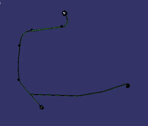
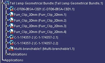
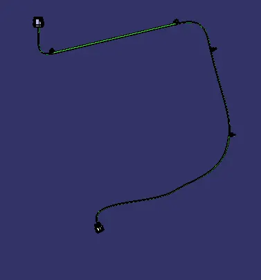
TAIL LAMP GEOMETRICAL BUNDLE:
TAIL LAMP EXPANDED TREE:
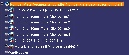
NUMBER PLATE GEOMETRICAL BUNDLE;
NUMBER PLATE EXOANDED TREE:
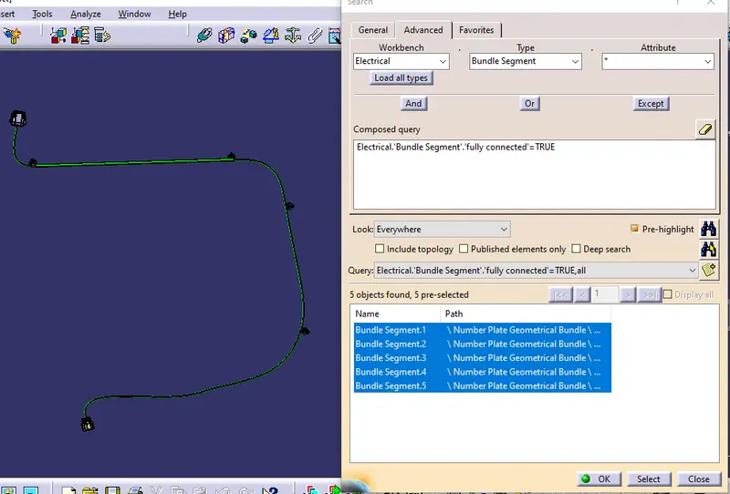
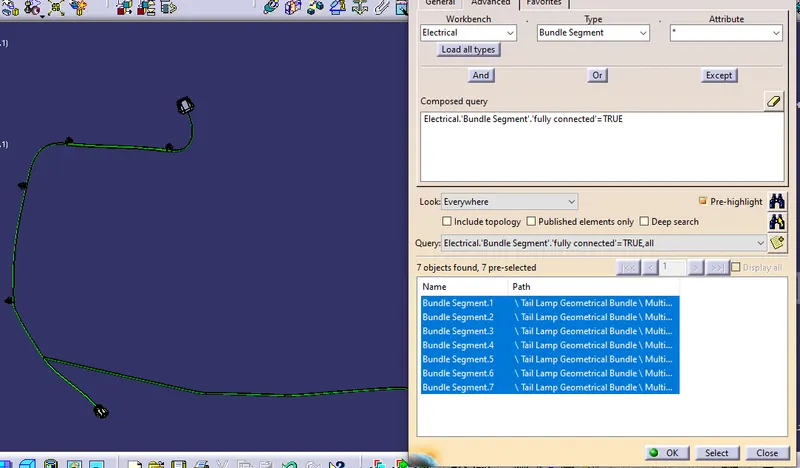
BUNDLE SEGMENT CONNECTIVITY:
FOR NUMBER PLATE:
FOR TAIL LAMP:
FLATTENING:
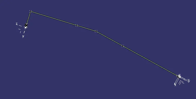
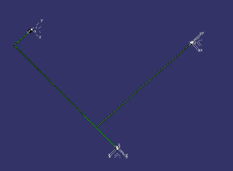
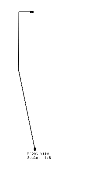
Drafting:
Drafting for Tail lamp geometrical bundle
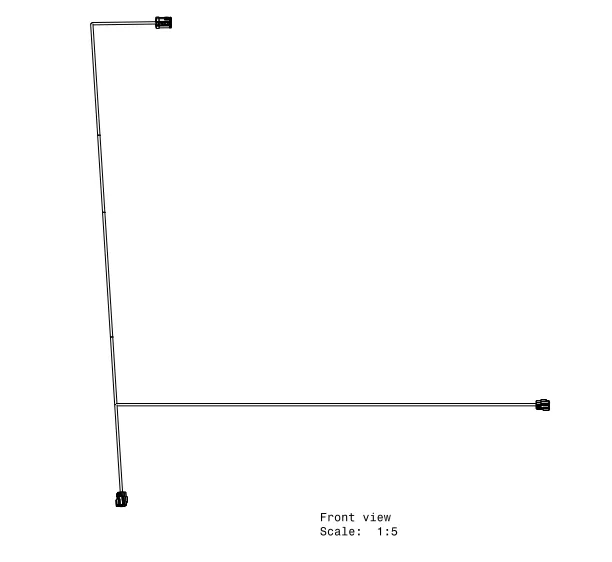
Drafting for number plate geometrical bundle:
CONCLUSION:
Hence the routing is created for the given Back door CAD model by the electrical connectors by using different work benches like Assembly design, Electrical part design, electrical assembly and installation and flatenning.
The created bundle segments are fully connected by using bundle connectivity segment