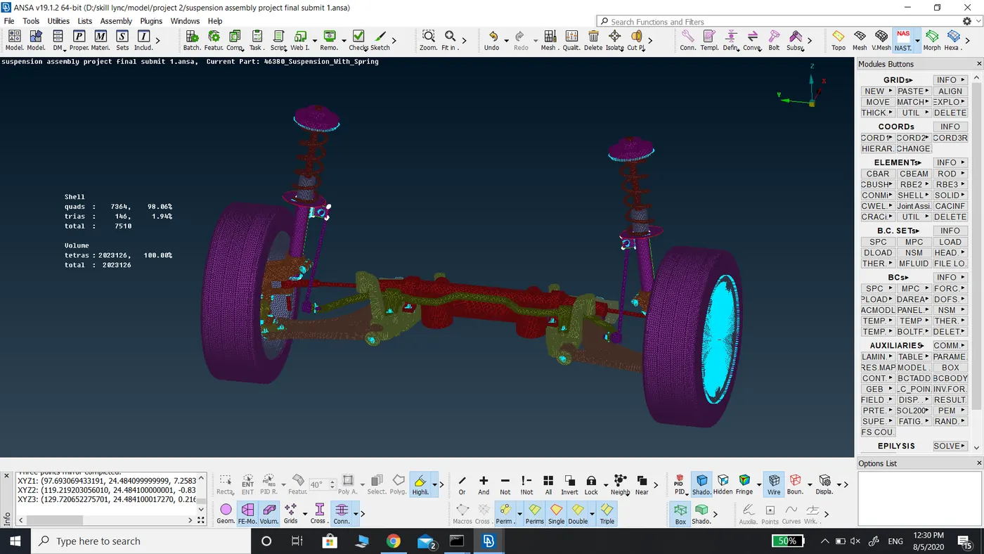
Mesh on Suspension Assembly.
Report on Suspension Assembly
Aim: For the given assembly, check for the geometrical errors and mesh with the given element Quality criteria. After meshing the component, the thickness has to be assigned for mid surfaces. Use tetra elements to model non-uniform thickness components. Also, use connections to connect the component as suggested in the Project-2 video
Quality Criteria for Tria Elements (Tyre and Rim):
|
S.No |
Quality Criteria |
Value |
|
1 |
Target/Average length |
6.5 |
|
2 |
Minimum Length |
5 |
|
3 |
Maximum Length |
10 |
|
4 |
Skewness |
45 |
Quality criteria for Mixed elements (For Midsurface only):
|
S.No |
Quality Criteria |
Value |
|
1 |
Target/Average length |
4 |
|
2 |
Minimum Length |
2 |
|
3 |
Maximum Length |
6 |
|
4 |
Aspect |
3 |
|
5 |
Warpage |
15 |
|
6 |
Skewness |
45 |
|
7 |
Jacobian |
0.7 |
|
8 |
Minimum Quad Angle |
45 |
|
9 |
Maximum Quad Angle |
135 |
|
10 |
Minimum Tria Angle |
30 |
|
11 |
Maximum Tria Angle |
120 |
Quality criteria for Tria (For other components):
|
S.No |
Quality Criteria |
Value |
|
1 |
Target/Average length |
4 |
|
2 |
Minimum Length |
2 |
|
3 |
Maximum Length |
6 |
|
4 |
Skewness |
45 |
Common Quality Criteria for Tetra elements are:
|
S.No |
Quality Criteria |
Value |
|
1 |
Tet-collapse |
0.2 |
Procedure:
- After downloading the model, topo command is applied separately to each volume in the suspension assembly to avoid triple con errors.
- Geometry check is performed to individual volumes to which topo command is applied to check for cracked faces, unchecked faces, triple cons, and single cons. The errors generated are fixed either manually or by applying auto fix.
- Once all the geometry errors are cleared the model is reviewed area by area to check for overlapping faces near corners of the fillets or where two or more fillets join. Those faces are deleted and created new faces using the faces-new command.
- As the suspension assembly components do not have a constant thickness and for some components, its thickness is greater than 5mm hence we have to use 3D mesh.
- For the generation of 3D mesh ortho tria element mesh with the above-mentioned mesh quality criteria has to be generated in the parent geometry.
- After solving all the errors found in the geometry check target length of required length is assigned to each component as mentioned in the objective of the model using length in command in mesh mode.
- The model is reviewed area by area to check the perimeters are matching the requirements.
- Defeaturing is done to those areas who have a length less than the target length. It is done using the cut command in macros in topo mode. Unwanted cons, Hotpoint, curved cons, and cons on straight surfaces are hidden for good mesh flow.
- After defeaturing the component, the geometry check is performed once again for geometrical errors.
- The model is opened in mesh mode and particular mesh quality criteria are entered in the quality criteria and mesh parameters are entered for the particular component that is to be meshed.
- Mesh is done using the Best mesh with ortho tria for good mesh flow.
- The holes are modeled such that they are captured with even number of nodes on both sides of holes to have smooth mesh flow.
- For circular surfaces zone cut is created with the width of target length i.e., 4mm to make good mesh flow.
- Once the component in the suspension assembly has meshed completely, it is reviewed area by area to check for the mesh elements failing for mesh quality criteria and also to ensure the fillets and other features are captured properly.
- And also, to ensure there are no kinks and dips in the ortho tria mesh as they lead to tet collapse mesh quality error while generating tetra element mesh.
- After clearing kinks and dips if found, the Volume mesh deck is opened for tetra mesh.
- To generate volumetric mesh, a volume must be defined. This is done using define command in volumes using auto-detect it will automatically detect the meshed component and generate volume.
- After the volume is generated, tetra mesh is generated using two methods. The first method is to click on list command in volumes and right-click on the volume generated and give remesh. In this command specify the type of tetra mesh to be applied. The second method is directed to click on the type of tetra element mesh to be generated under an unstructured mesh deck.
- After generation of the tetra element mesh the component is viewed in shadow drawing style to check for tet collapse mesh quality error and is eliminated using move free option in Grids in mesh mode. In case there are more no. of elements failing for tet collapse mesh quality criteria use fix quality under improving in volume mesh mode.
- To the generated volume mesh PID is already assigned when defining the volume for 3D mesh hence there is no requirement for individually assigning PID for each component.
- The component is reviewed area by area to find the necessary connections.
- For generating Cluster type of connections, Elements RBE2 many nodes command in NASTRAN mode.
- For generating Bolt type of connections, RBE2 many nodes command in NASTRAN, then again RBE2 two nodes select the center point of the connections.
- Hence the connections are generated to the necessary areas.
- The above steps are repeated till all the components are meshed and connections are applied.
- Initially, as the suspension model is symmetric its mirror half was deleted to complete the model with the least time. After the completion of mesh generation and connections, its mirror half is generated using transform command in the symmetric tab.
Learning Outcomes:
- Nastran Elements deck
- Defining connections for different types of components in the suspension assembly.
- Defining Volumetric mesh for components with the varying thickness or whose thickness is more than 5mm.
Conclusion.
The given model suspension assembly to which 3D mesh is generated and appropriate connections are made.
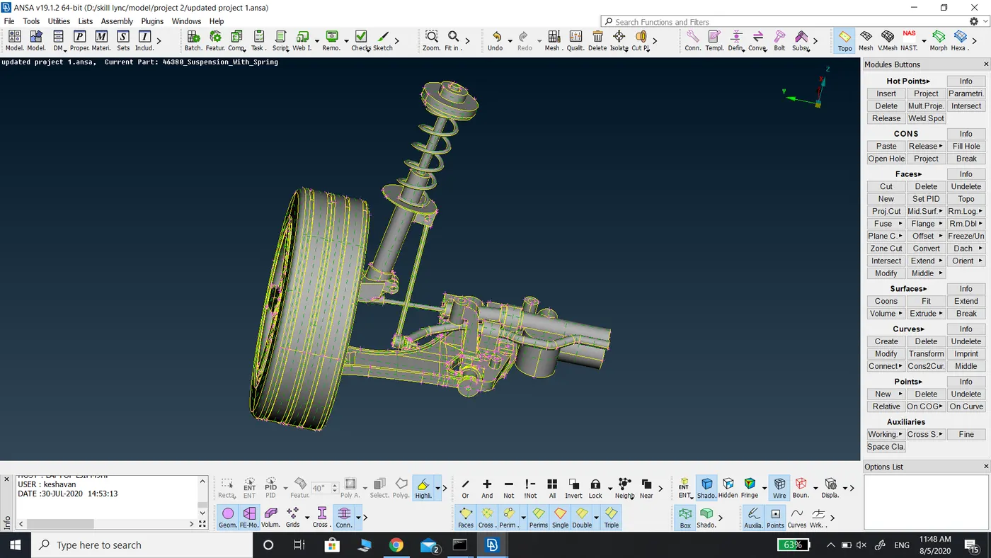
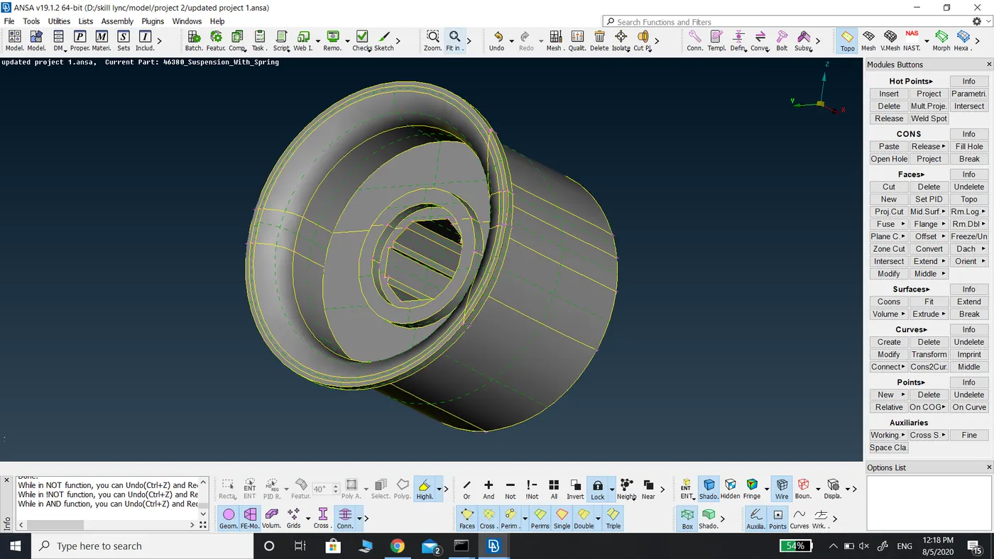
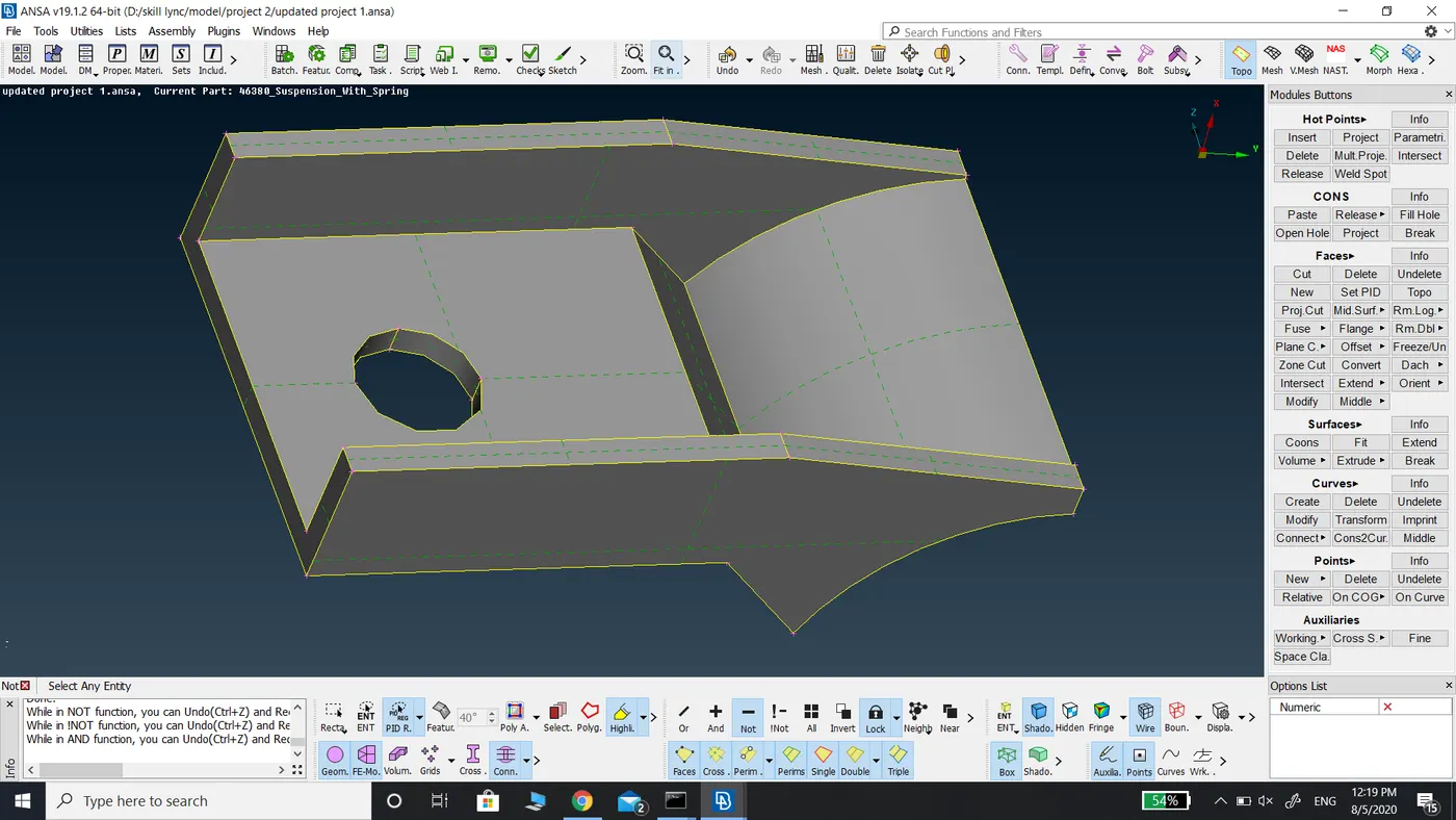
Parent model.
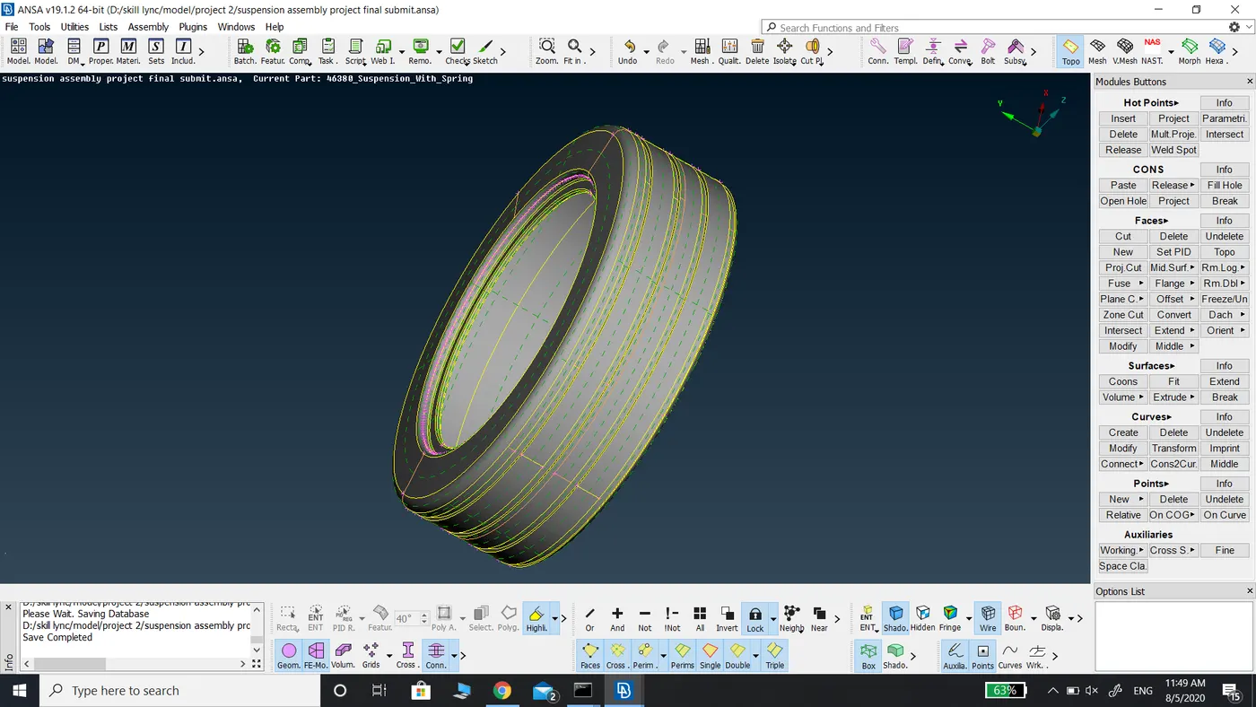
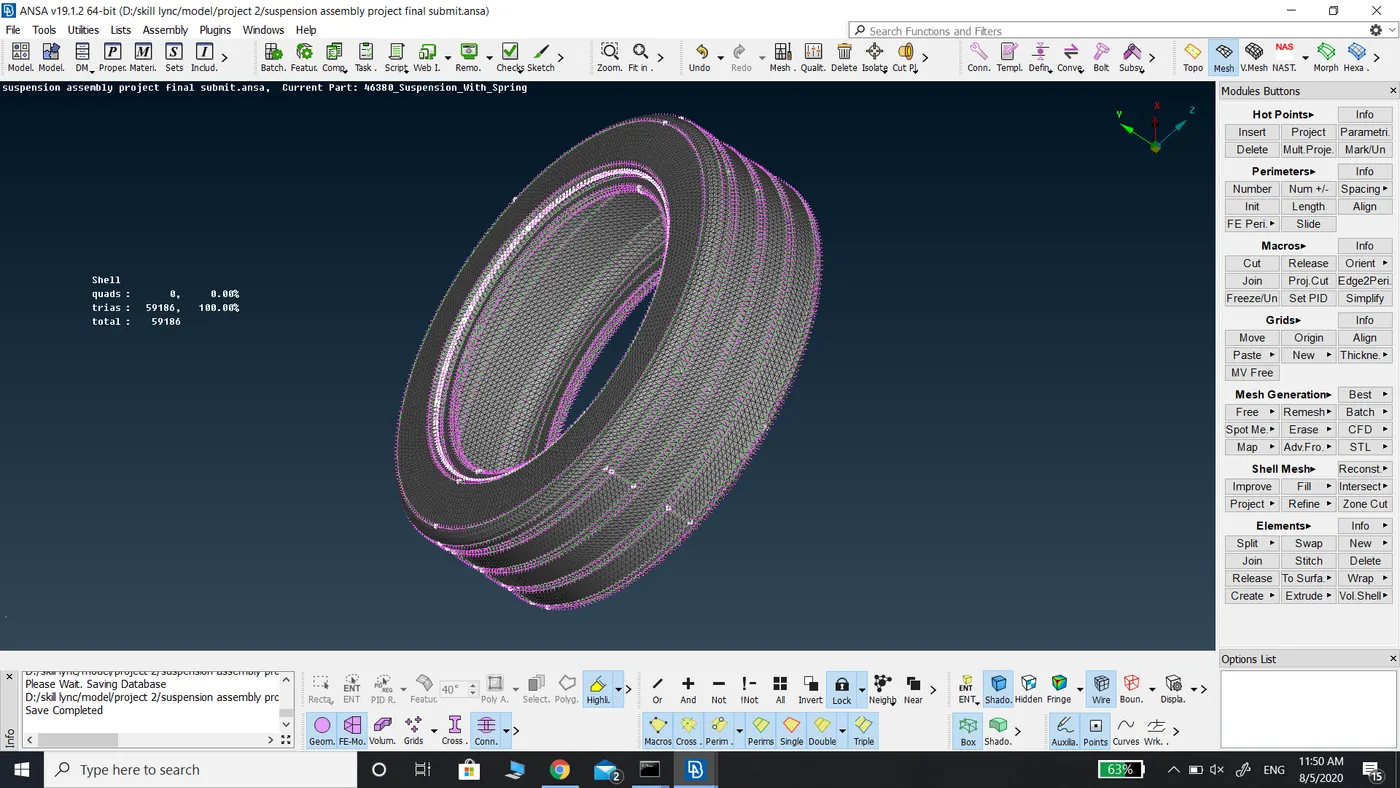
The meshing of the tire.
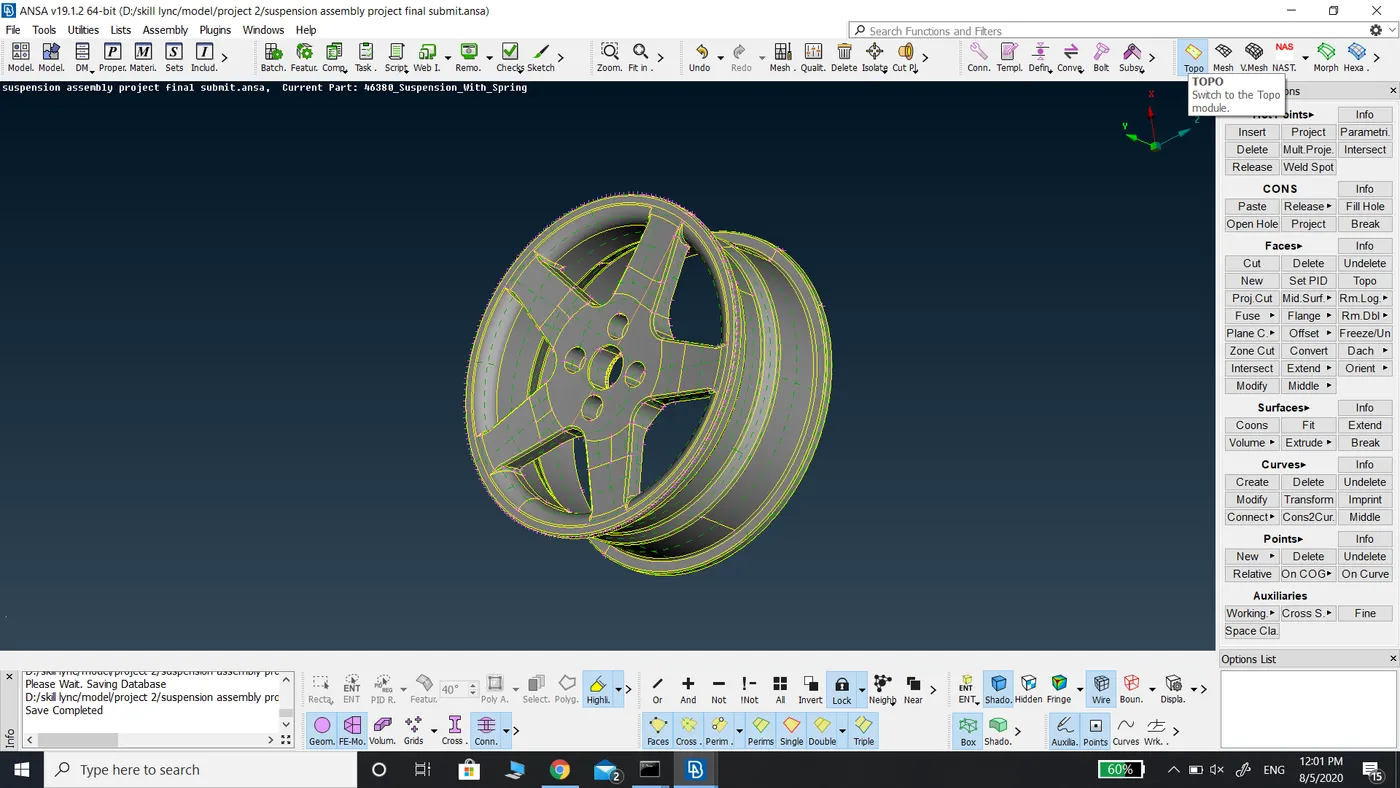
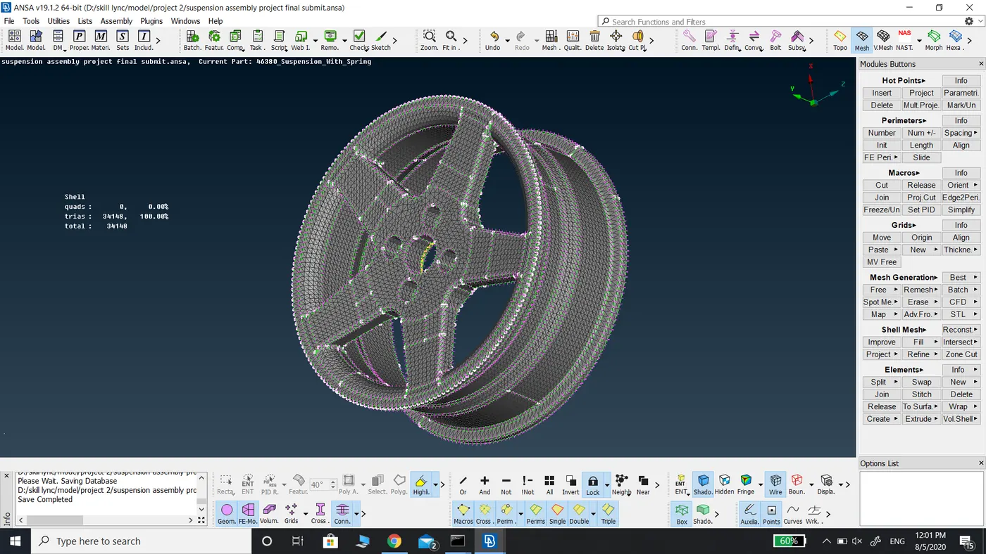
The meshing of Rim.
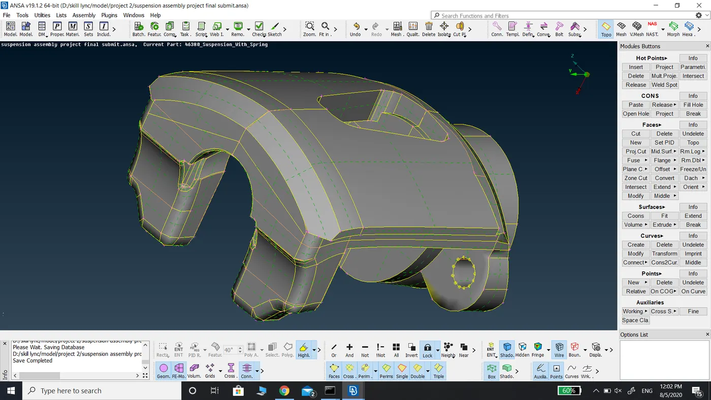
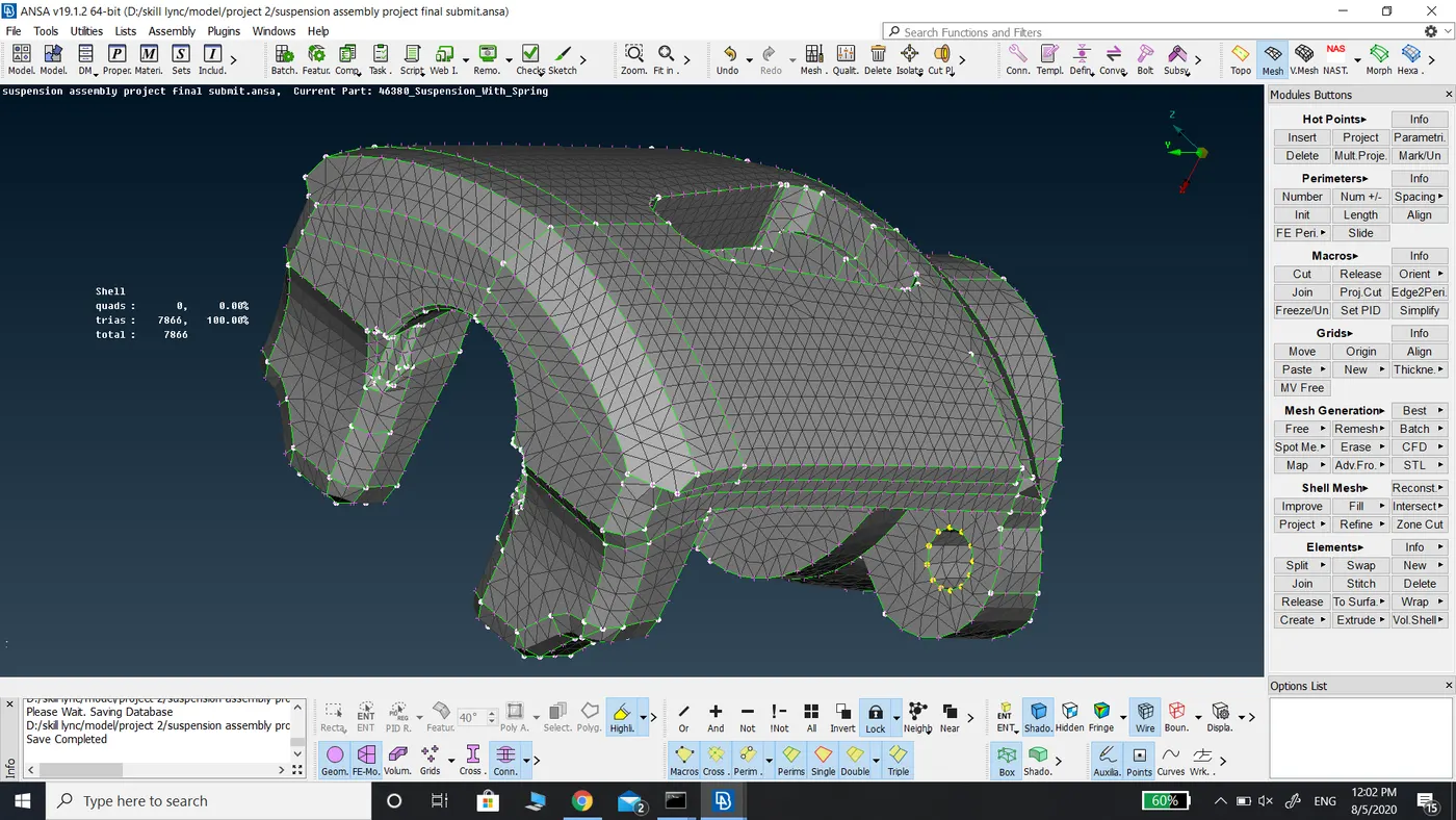
The meshing of Brake caliper.
The meshing of the brake disc.
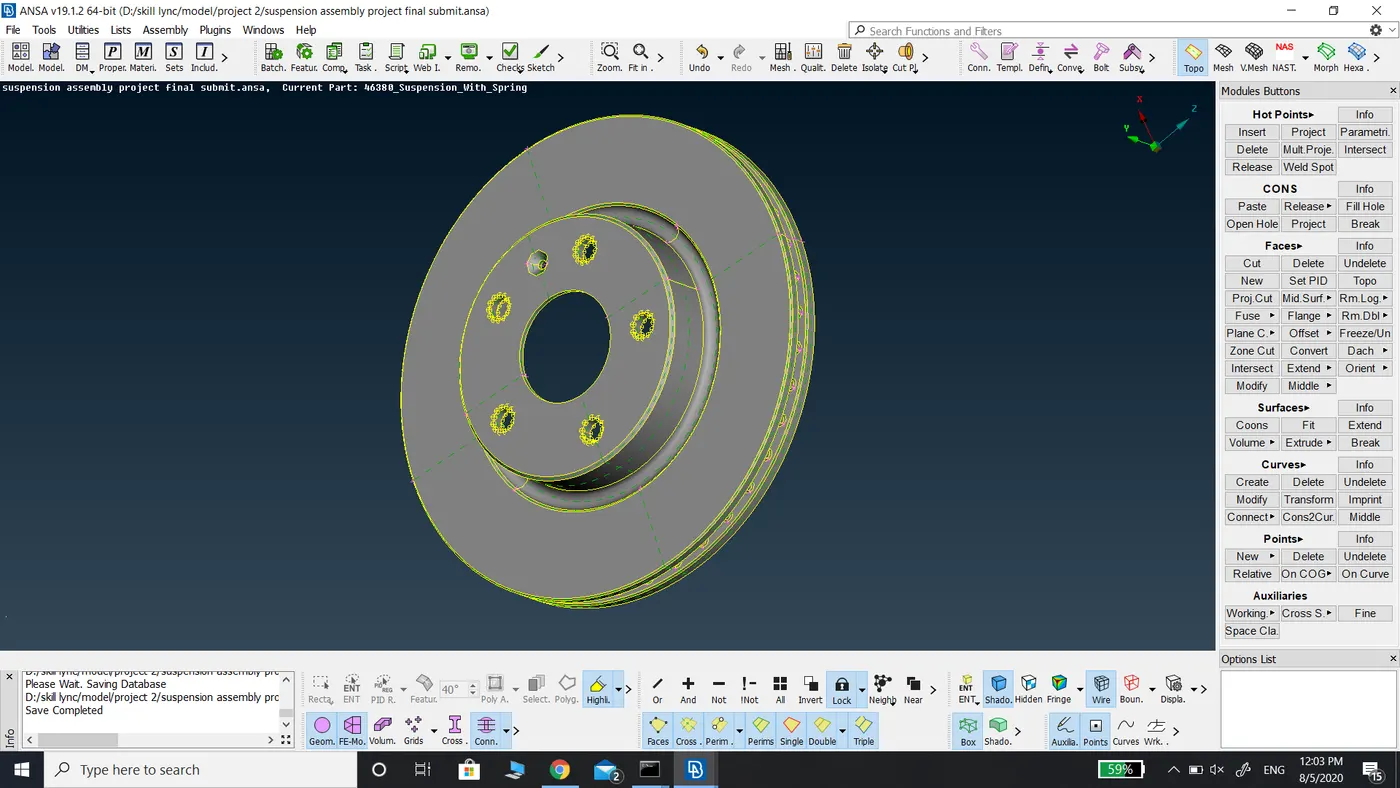
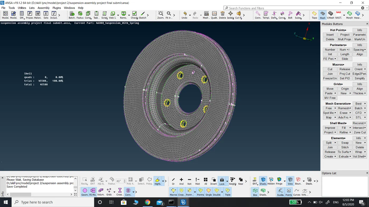
The meshing of the wheel hub.
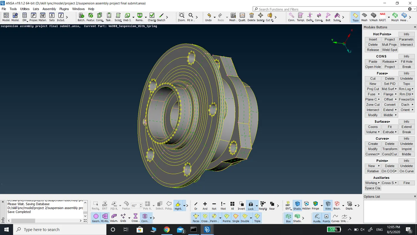
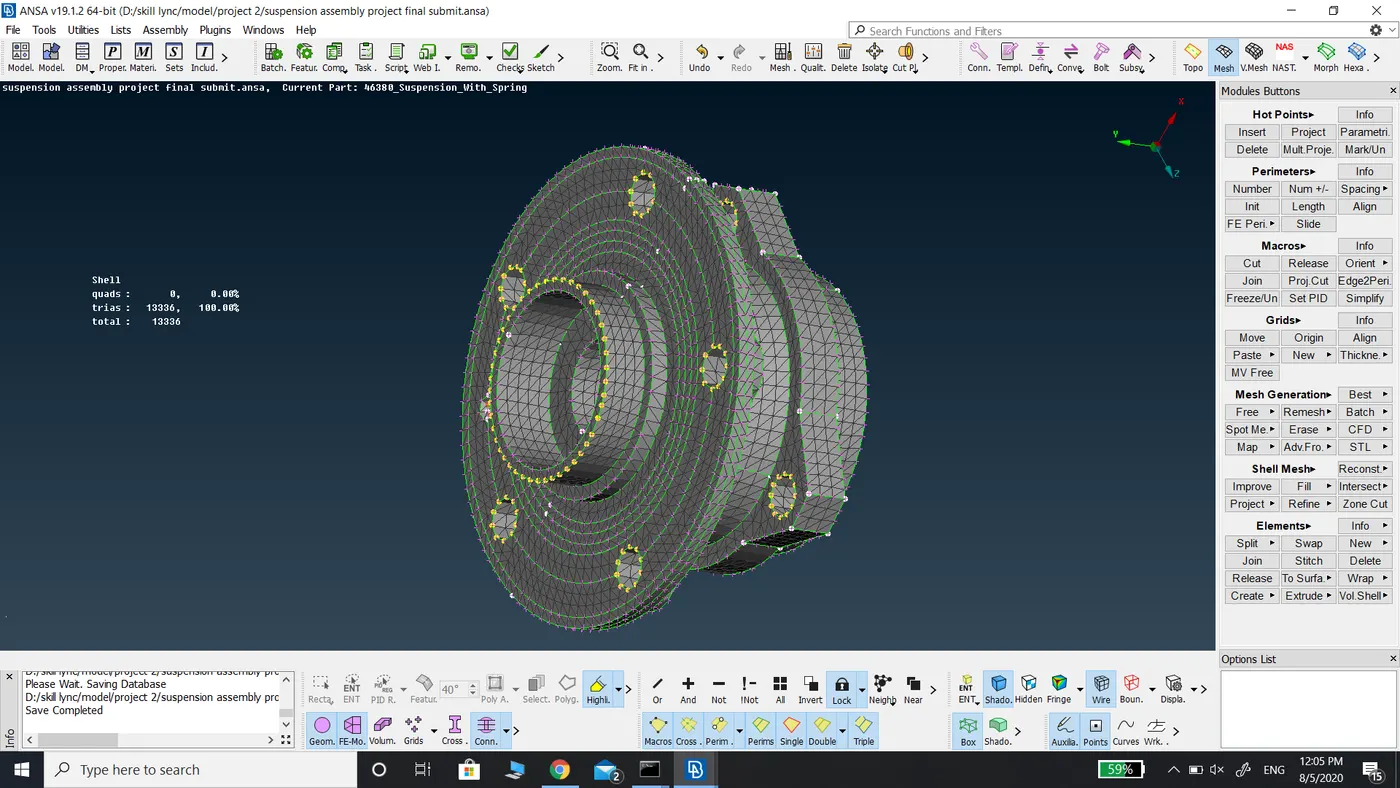
The meshing of upright.
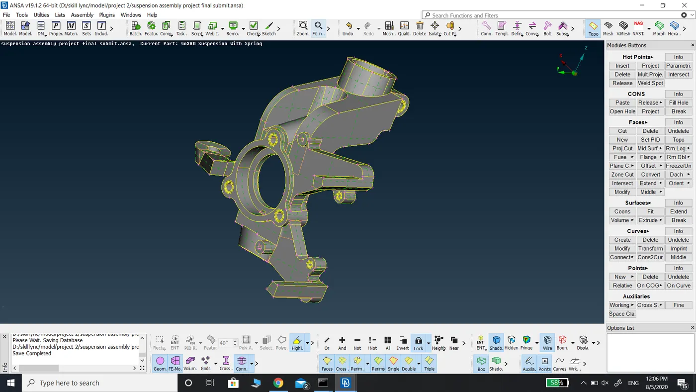
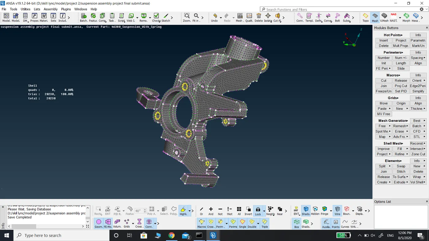
The meshing of Rack and Pinion Assembly.
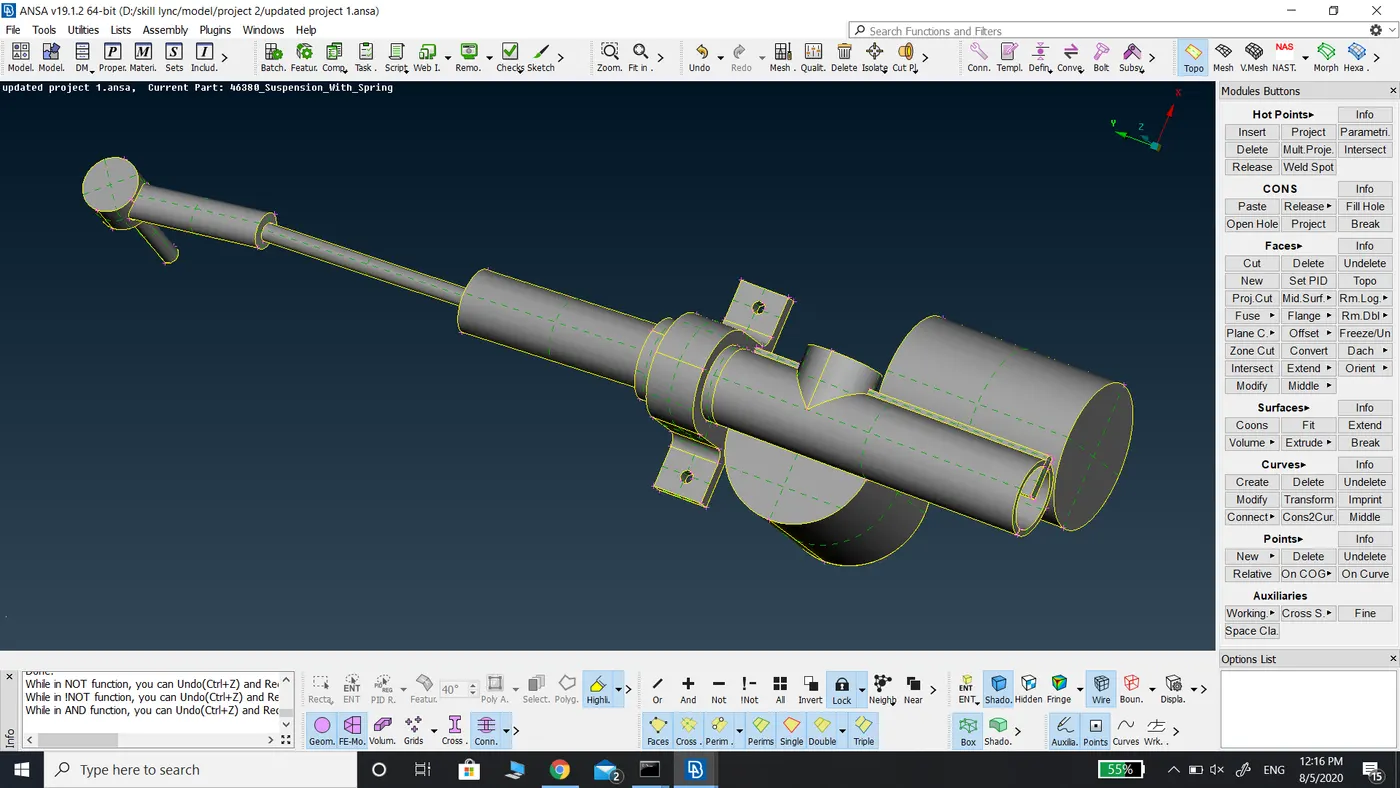
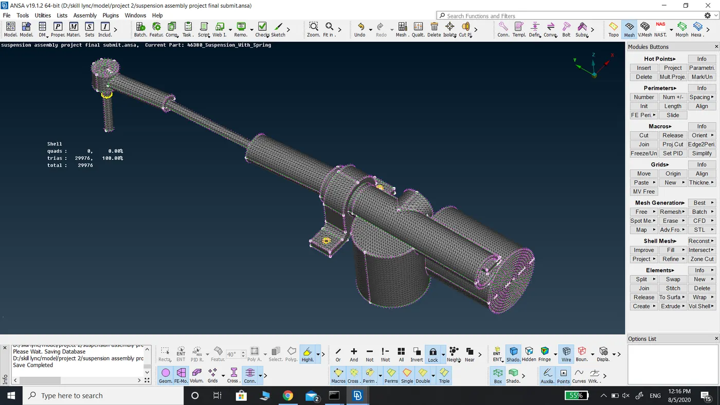
The meshing of Shock Absorber.
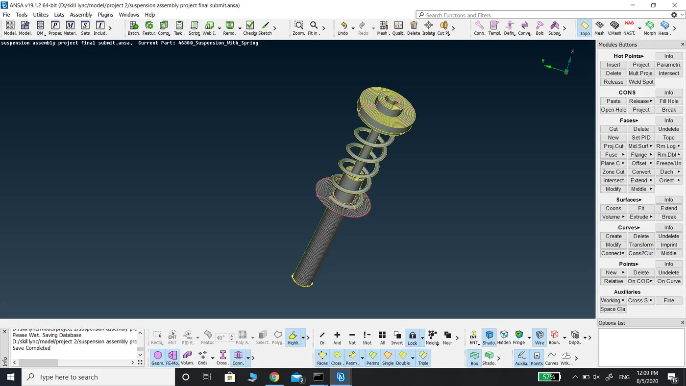
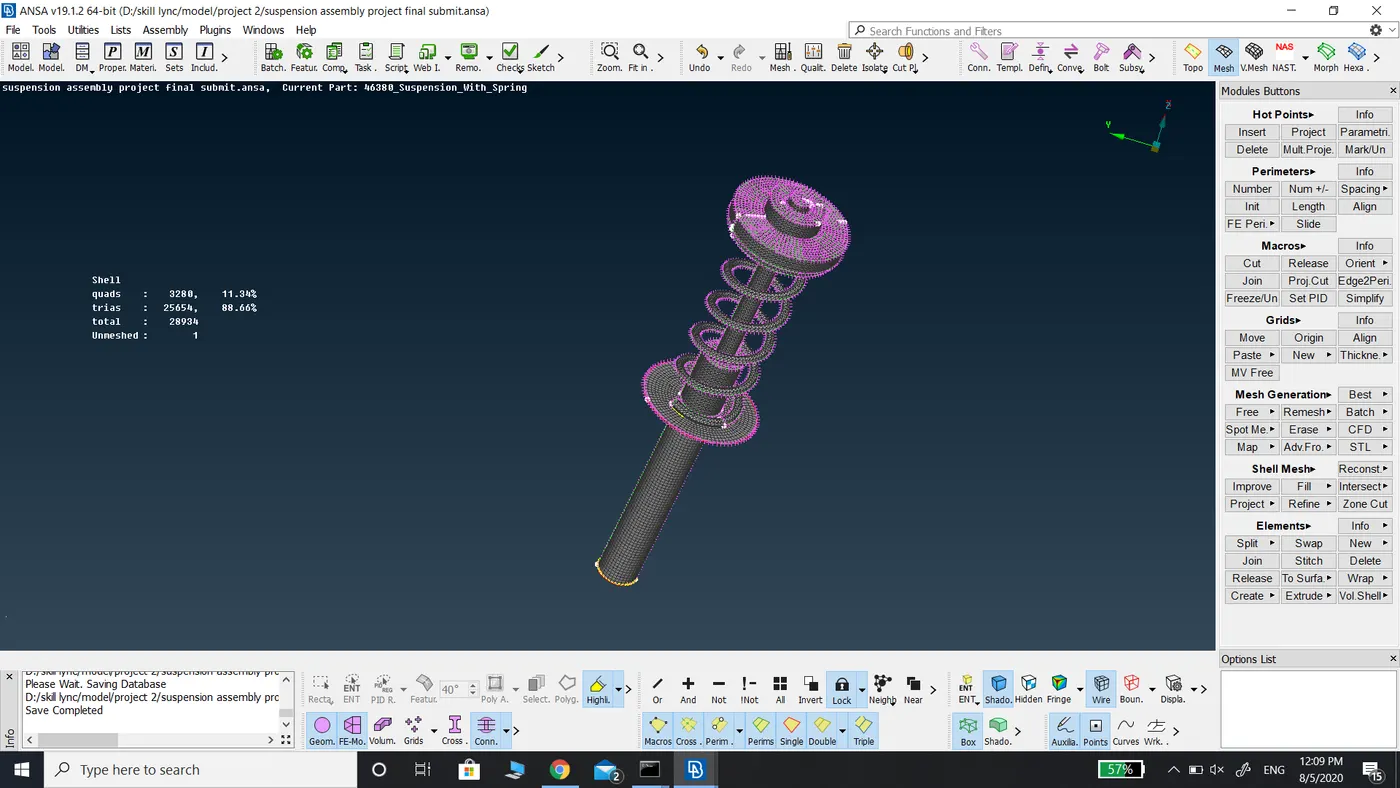
The meshing of the ball joint.
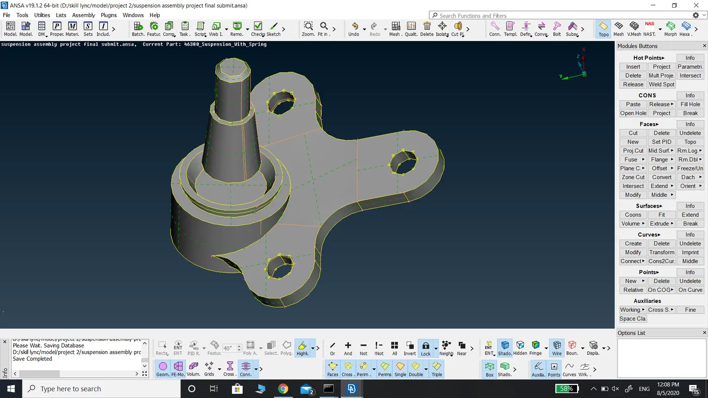
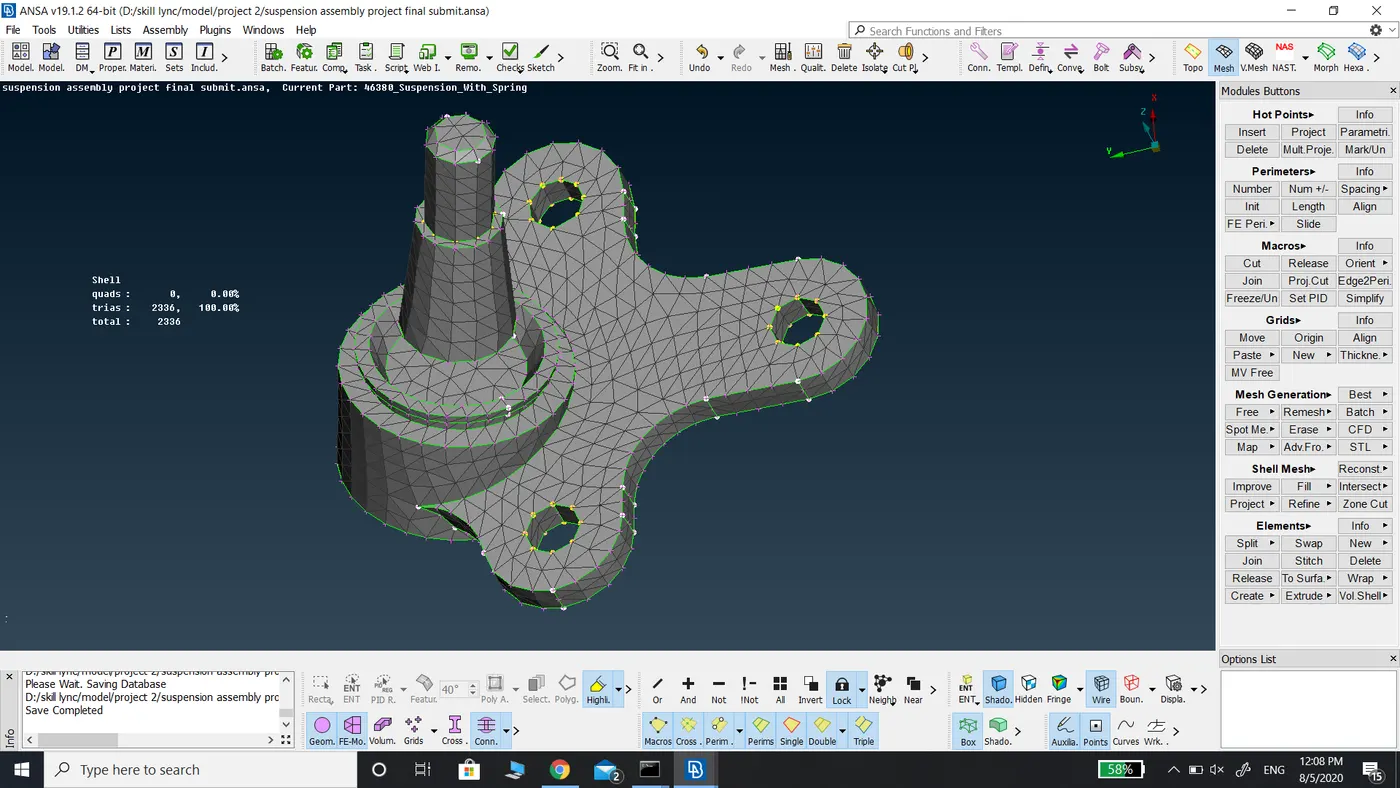
The meshing of other components in the assembly.
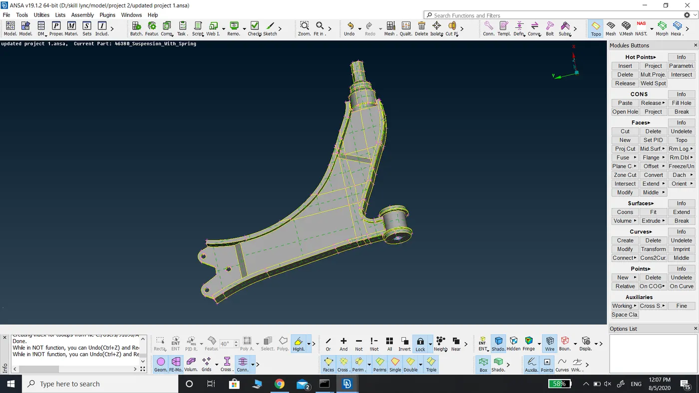
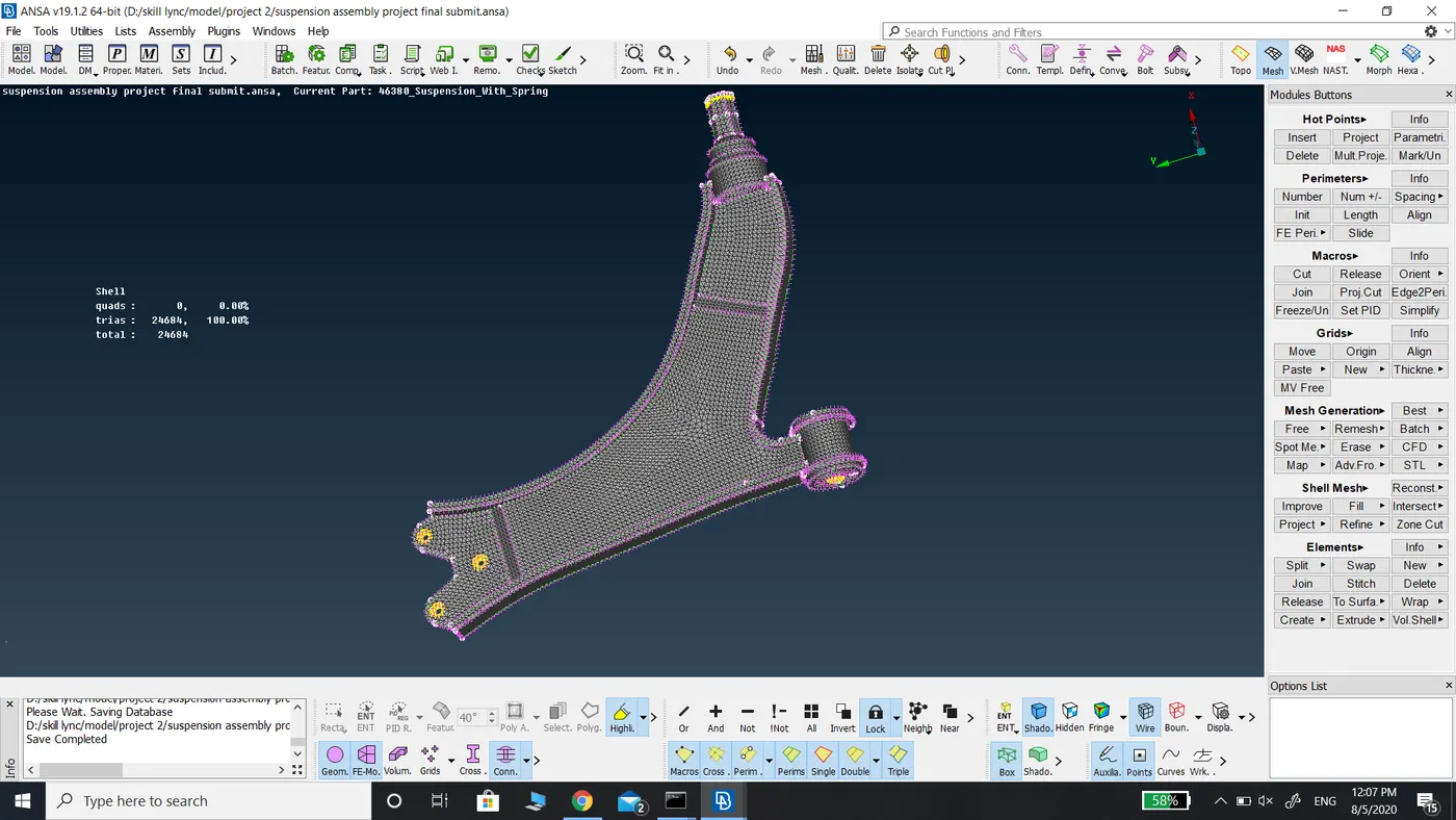
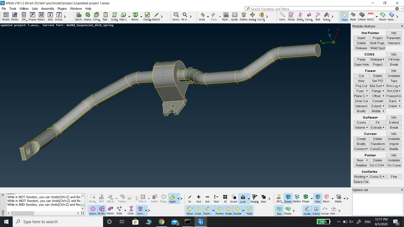
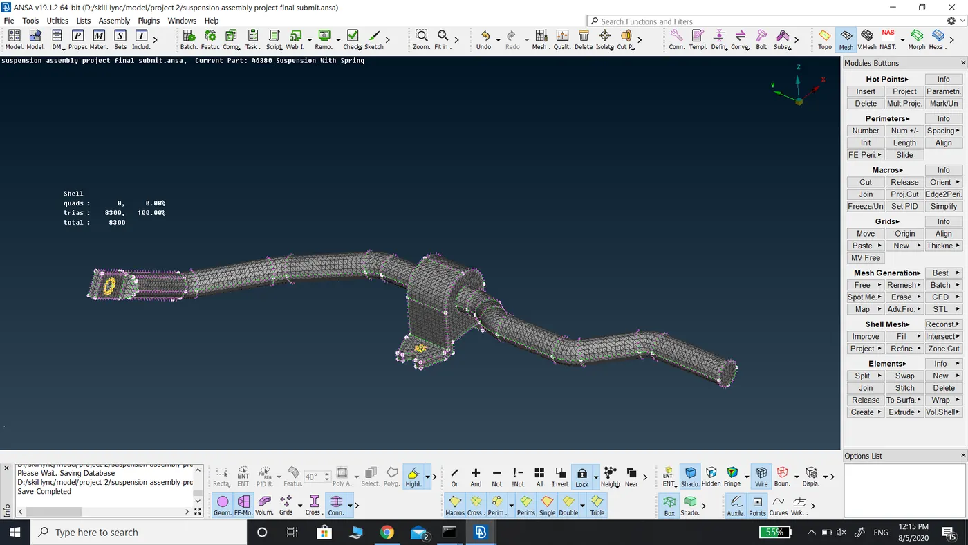
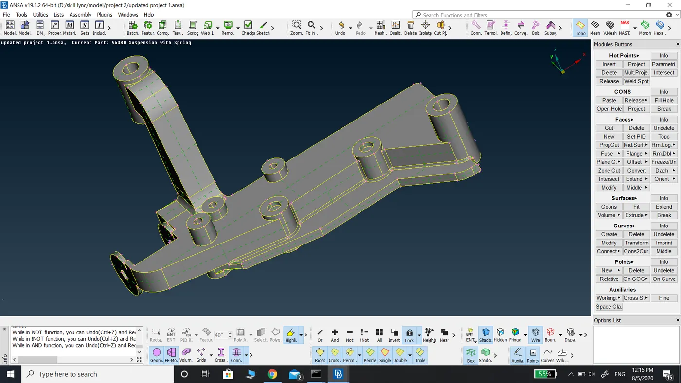
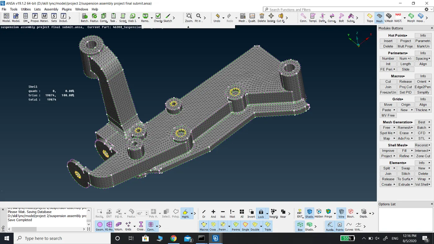
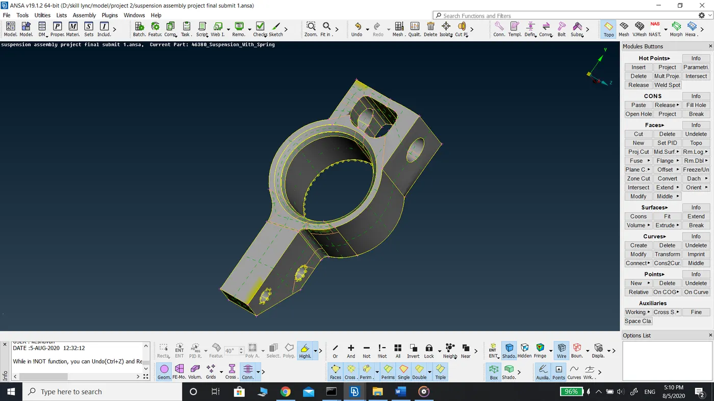
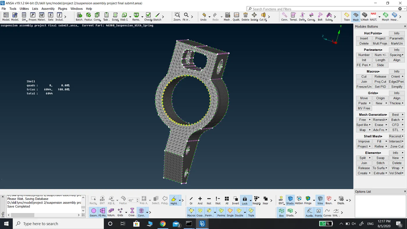
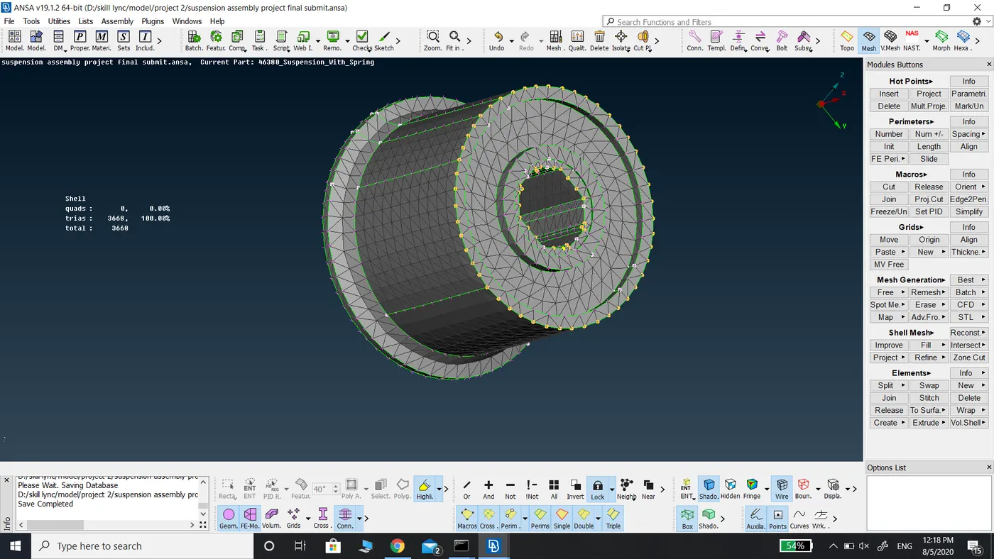
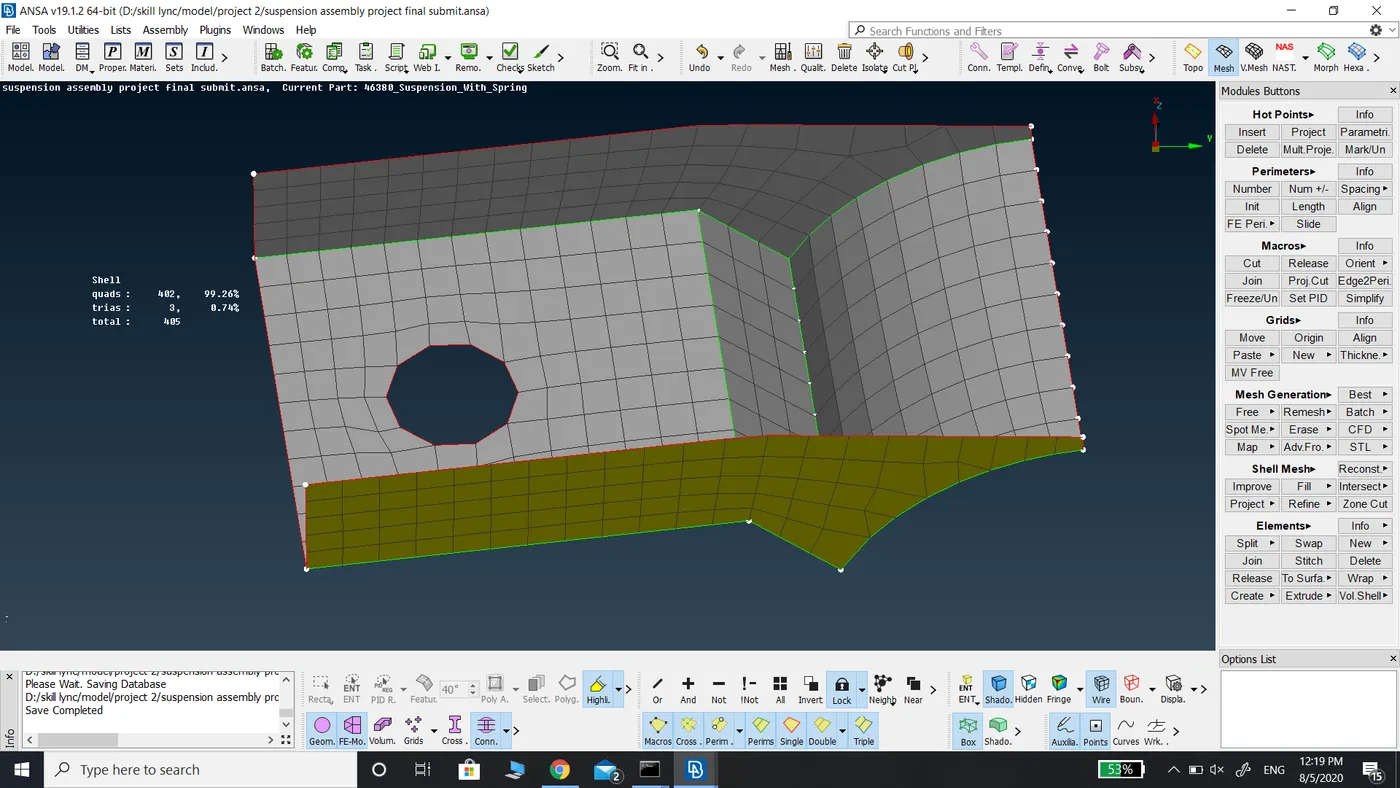
Tetra Meshing and connections done for half of the suspension assembly.
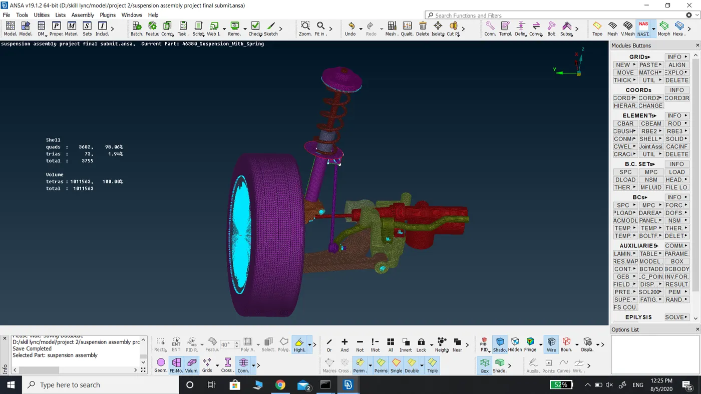
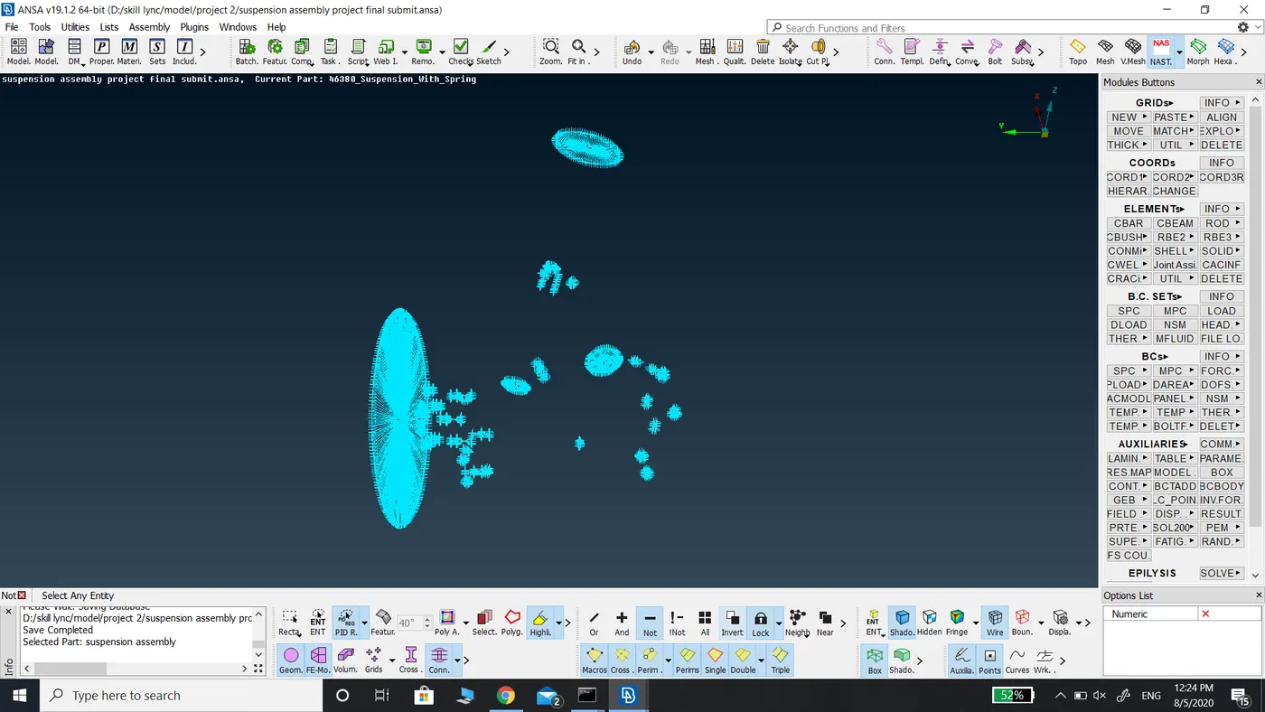
The shadow drawing style of half of the suspension assembly.
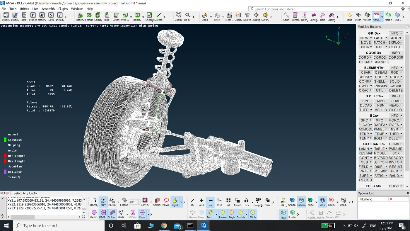
Entire suspension model