Project 2
AIM: To route the wiring harness on given Tail Gate and prepare and flatten view drawing in CATIAV5.
STEPS:
- Create context assembly.
- Define the connectors geometrically and electrically
- Define clips
- Add all the components to the geometrical bundle assembly and locate the components
- Route all the components
- Add protective coverings on the bundle segments.
- Extract and flatten the harness.
- Create the front view of the harness in drawing.
Creating context assembly:
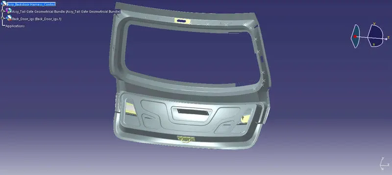
Tail gate model is downloaded and saved.Main context assembly is created in which geometrical bundle assembly and Tail gate model are added to the assembly as shown below.
Define connectors
In this model, five connectors are used.
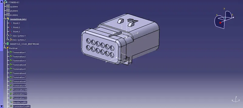
C-776438 is the male housing connectors with 12 terminations. This is the interconnection connector.
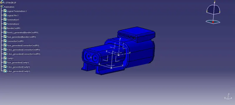
C-DTM-04-2P is the housing for male terminal, with 2poles. This is used for two brake lights and two plate lights.Connector:
Define Clips:
In this model, Fir Tree clips are used.
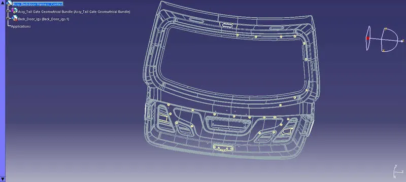
The picture below shows the places where holes are to be made on the car sheet metal frame for Fir treeclips.
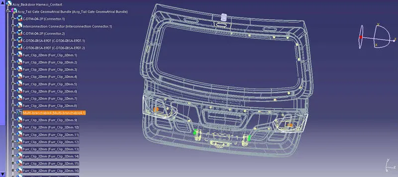
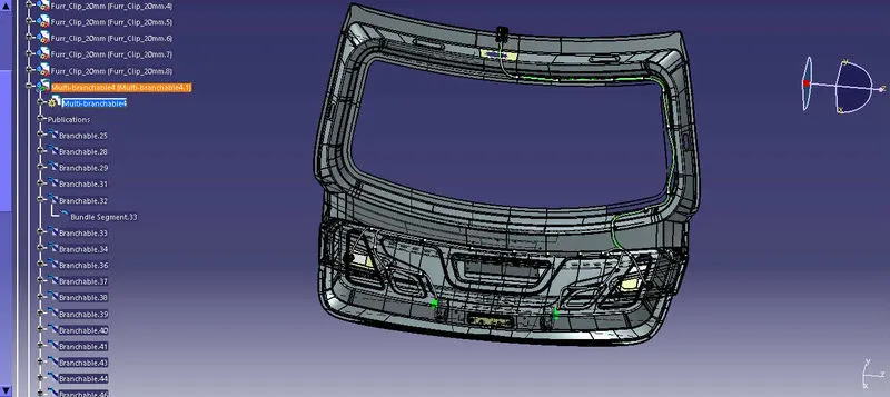
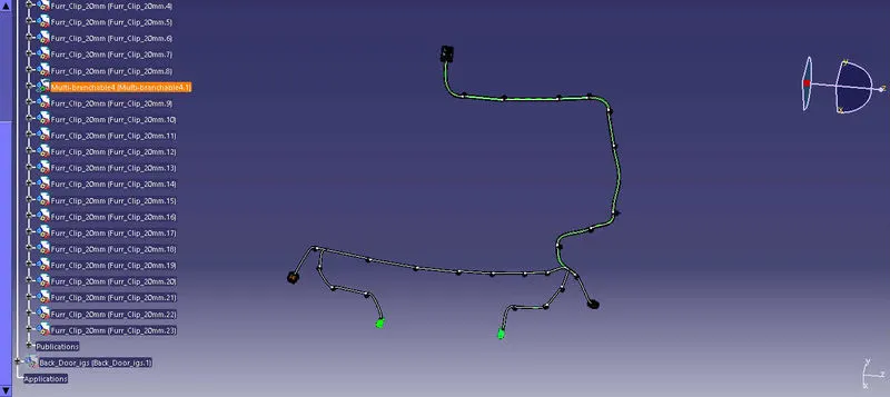
Route the components.The diameter of the main bundle segment starting from interconnection connector is assumed to be 10mm. And the bundle segment leading to the back lights are assumed to be 5mm. The bend radius ratio is assumed to be 1.5. Slack is provided wherever required ranging from 1-5%. While routing some rules aare kept in mind like:
- The branch length must be greater than 50mm.
- The minimum length between the clip and the branch points must be 25mm.
Adding protective coverings to the bundles are important to keep bundles together and to protect it from wear and tear. Here slit COT tubes are used of 15mm and 10mm for the bundle segments of 10mm and 5mm respectively.
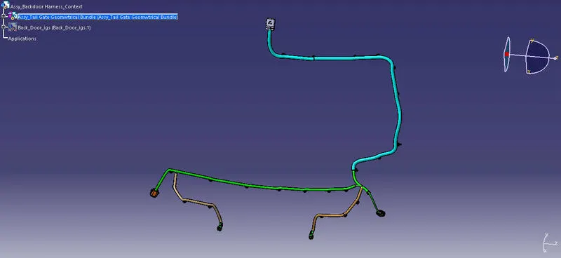
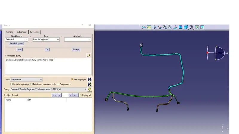
Bundle continuity check needs to be performed to ensure that the bundles are fully connected.Picture below shows that there are no errors in the bundles and they are fully connected.
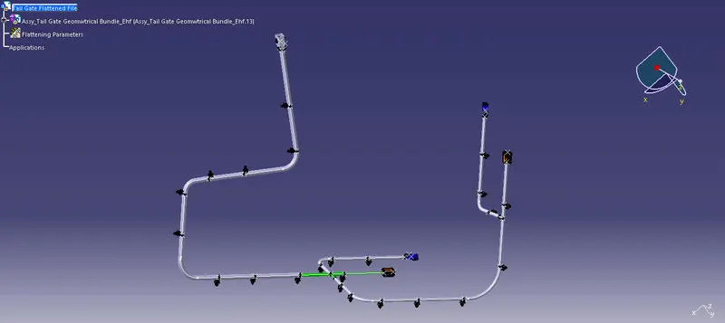
The picture below shows the flattened view of the harness. For this the geometrical bundle has to be extracted to the newly created flattened file, in the Electrical Harness flattening module. While defining flattening parameters it is made sure to use Single line for bundle segments and double line for Protective coverings. Flattening is done along the face plane of the connector. Some features like bend and rotate has been used to gie desired shape to the bundles.
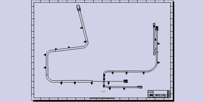
After flattening, 2D drawing file is created of the format A0 ISO and front view of the harness is created along the face plane of the connector. In the dress-up setting s 3D wireframe is enabled to make the bundle segments visible.
Conclusion: Routing of the Tail gate assembly is done and flattened view drawing is prepared in CATIA V5. While doing so all the packaging rules and constraints where considered.