Project 2
a.
Given:Battery Resistance=2 milli ohm=2*10-3Ω
As per the drive cycle:
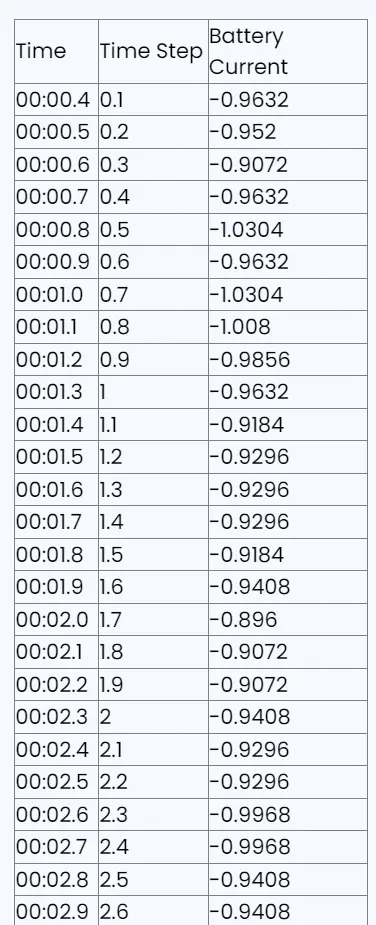
Time corresponding to maximum current(-0.896 A)=2 minute=120 seconds
Now,
Average heat generated by battery=Joule heat+ Entropic heat
Since, Entropic factor=2
Average heat generated by battery=i2Rt+2*(Joule heat)
Average heat generated by battery=i2Rt+2.i2Rt=3.i2Rt
Maximum heat generated by battery=3*[(Maximum current)2*R*Time taken]
Maximum heat generated by battery=3*[(-0.896)2*(2*10-3Ω)*120 s]
Maximum heat generated by battery=(3*192)
kW=576kW
Answer:
Maximum heat generated by battery=576kW
b.
Objective: To find the SOC of 3S2P battery pack for given drive cycle input.
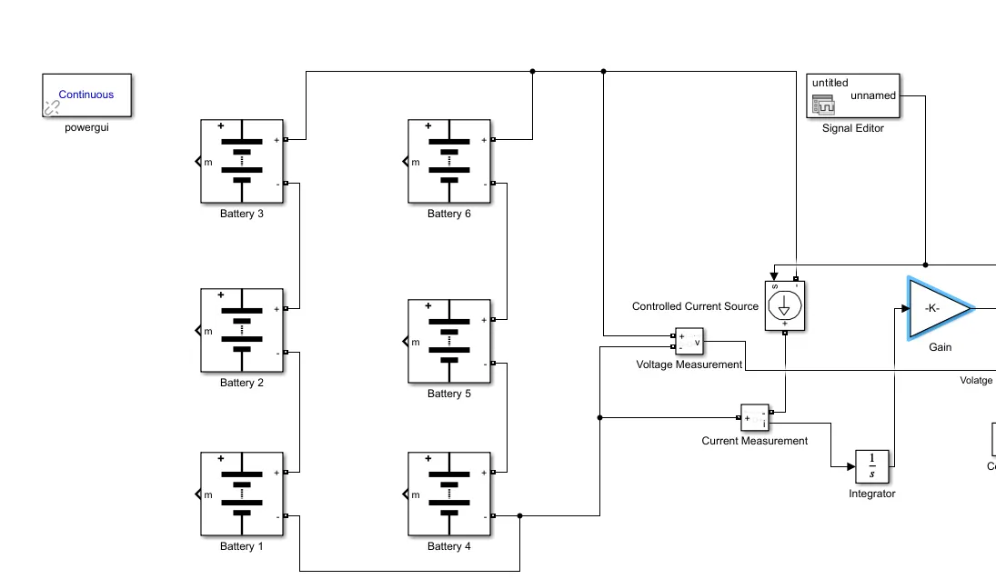
STEP 1(Design): We add six 'Battery' mask blocks (two sets of 3 each) in the Simulink and connect the positive terminal of first battery to negative terminal of second battery and positive of second battery to negative terminal of third battery. Similarly, we connect the second set of three batteries in series connection. Now, the negative terminal of first battery and fourth battery are connected to a common bus junction and positive terminal of third battery and sixth battery from both sets are connected to a common bus junction to create a parallel connection between two sets. This arrangement results in design of a 3S2P battery pack configuration.
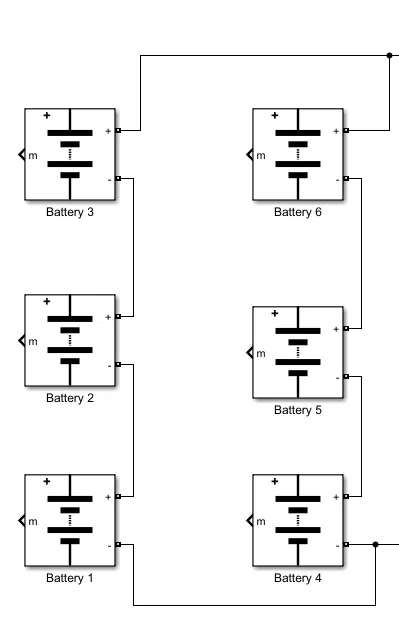
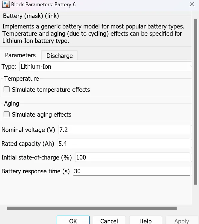
The properties of each battery block are
as follows:
Each battery has a default nominal voltage of 7.2 Volts, Initial State of charge (SOC) value as 100%
STEP 2: Now we add 'Voltage Measurement' block to the model and connect it to the respective overall positive and negative terminals of battery pack. The output of this block is connected to the Scope' block to fetch the voltage characteristics of battery pack while discharging.
Step 3: We add a 'Signal editor' block to the 'controlled current source' block via 'current measurement ' block, to the overall positive and negative terminals of battery pack.
The signal editor block has a signal input in form of drive cycle data.
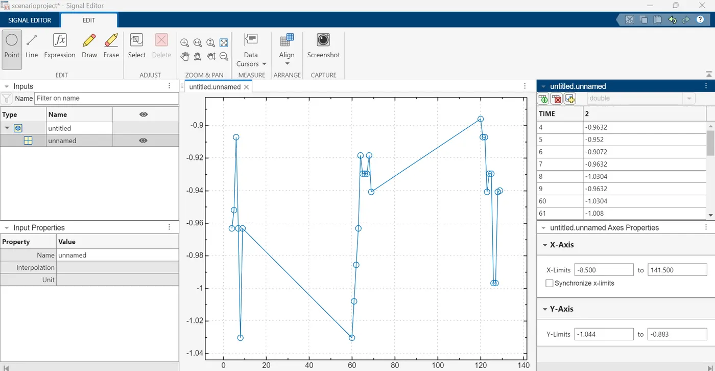
When we give this signal as input to the battery pack via 'controlled current source' it converts the Simulink input signal into an equivalent current source. The generated current is driven by the input signal of the block. The signal current input is given by creating a variable in Matlab workspace and then selecting 'Create Scenario from workspace' in signal builder.
Signal editor block is connected to negative terminal of 'controlled current source' which is connected to the negative terminal of 'current measurement' block which is connected to battery pack negative terminal. Now the output/discharge current signal from positive terminal of current measurement' block is connected to the 'Scope' block. The input signal current acts as a accelerator throttle input which in turn activates the battery power consumption of the vehicle and it start discharging. Hence the output signal to the Scope block records the discharge current of battery pack. We also add a 'powergui' solver block to carry the Simulink calculations in this complex model.
Theory:
The State of Charge (SOC) of a battery pack varies with discharge current due to several factors inherent to the battery chemistry and its operational conditions:
Peukert Effect: At higher discharge currents, batteries experience higher internal resistances, which reduce the effective capacity of the battery. This means that the battery appears to have less energy available than at lower discharge currents. Consequently, at higher discharge currents, the SOC decreases more rapidly compared to lower discharge currents.
Voltage Sag: When a battery is subjected to high discharge currents, the voltage across the terminals may drop more significantly due to internal resistance. As a result, the SOC estimation based on voltage measurements may indicate a lower SOC than the actual remaining energy in the battery.
Heat Generation: High discharge currents lead to increased heat generation within the battery cells. Elevated temperatures can affect the battery's performance and capacity, potentially accelerating degradation. Battery management systems (BMS) may adjust the SOC estimation algorithm to account for temperature effects accurately.
Chemical Processes: The rate of certain chemical processes within the battery, such as ion diffusion, can be influenced by the discharge current. Higher discharge currents may lead to limitations in these processes, affecting the overall battery performance and SOC estimation.
In practical terms, this means that under high discharge currents, the SOC of a battery pack tends to decrease more rapidly compared to lower discharge currents. This phenomenon is crucial to consider in applications where high power demands are common, such as electric vehicles or grid-scale energy storage systems. Accurate SOC estimation algorithms, coupled with appropriate battery management strategies, are essential to ensure optimal performance and longevity of the battery pack.
Step 4: The positive terminal that is output of 'Current measurement' block is connected to 'Integrator' which is then connected to a 'Gain' block operator , which is given with a constant value of 1/10.8*3600 for calculation of SOC.
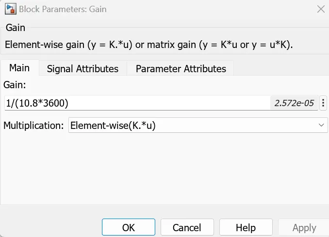
The formula for calculating SOC is given as:
SOC=1-∫(Current/Maximum capacity of battery pack)
Here,
Maximum capacity of 3S2P battery pack=2*(Rated capacity of each battery )
Note: We consider the parallel cells for calculation of battery pack capacity .
Maximum capacity of 3S2P battery pack=(2*5.4)Ah=10.8 Ah=(10.8*3600)Ampere. secondsWe get the discharge current as output of 'current measurement' block.
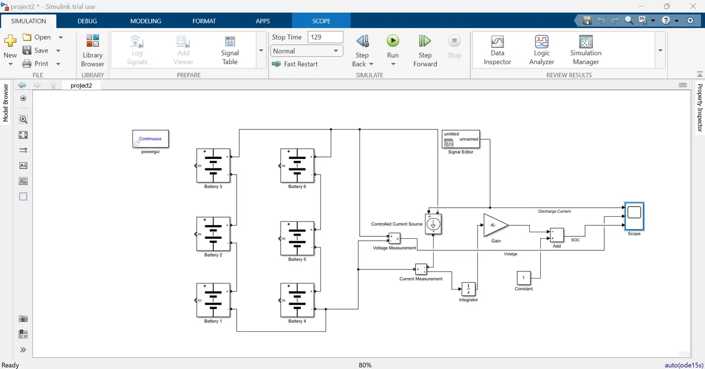
Step 7: We run the simulation for the battery pack model for 129 seconds (since input current source signal is recorded upto 2 minutes and 9 seconds seconds as per given drive cycle)and observe the Discharge current, Voltage, and SOC characteristics.
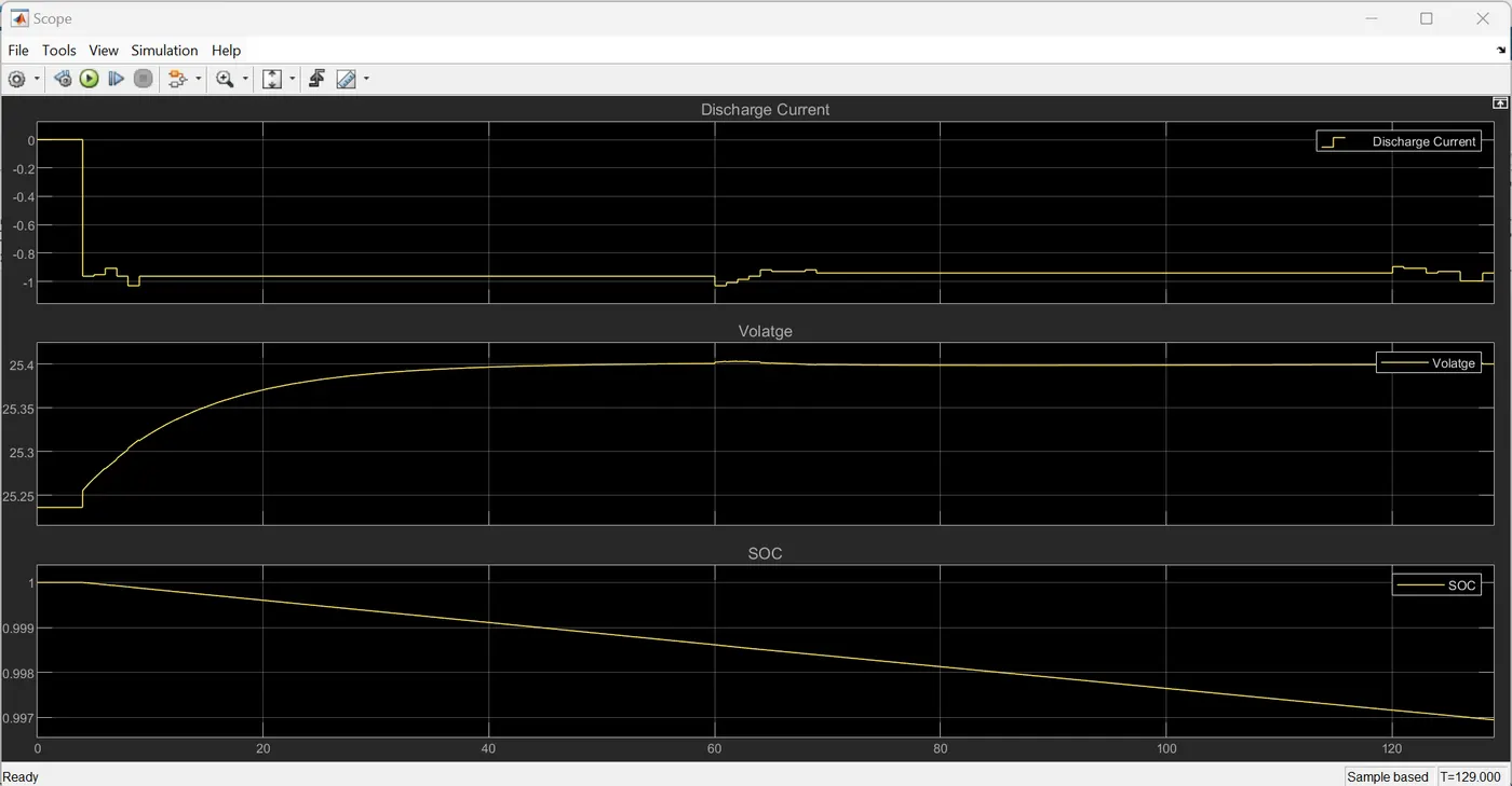
Conclusion: We can observe that current from the battery pack decreases due to discharging. Further the voltage increases as the discharge current decrease .The state of charge (SOC) of battery pack decreases as the battery pack discharges over the time.
The value of SOC decreases from 1 i.e. (100%) and approaches zero (almost) as the battery pack discharges over the time.