Project 2
Project Summary:
Automotive Backdoor Wiring Harness Design
Objective: Design a wiring harness for the backdoor of an automotive vehicle using CATIA V5, ensuring efficient routing, proper component integration, and compliance with safety standards.
Key Steps:
Requirements Gathering: Understand specifications for wires, connectors, length, and insulation.
Assembly Creation: Initiate a new assembly in CATIA V5 for the project.
Route Sketching: Sketch the path for the wiring harness, considering vehicle layout and avoiding obstacles.
Component Assembly: Assemble components in the assembly based on the sketched route.
Wire Routing: Utilize the Electrical Harness Installation workbench to route wires accurately.
Connector Placement: Position the connectors along the harness route.
Interference Checks: Perform checks to avoid interference with other vehicle components.
Protective Covering: Add protective coverings like conduit or tape to shield wires from damage
Documentation: Create drawings and documentation for manufacturing and assembly.
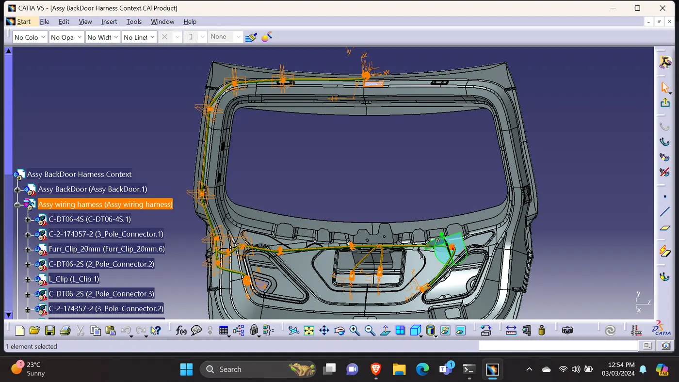
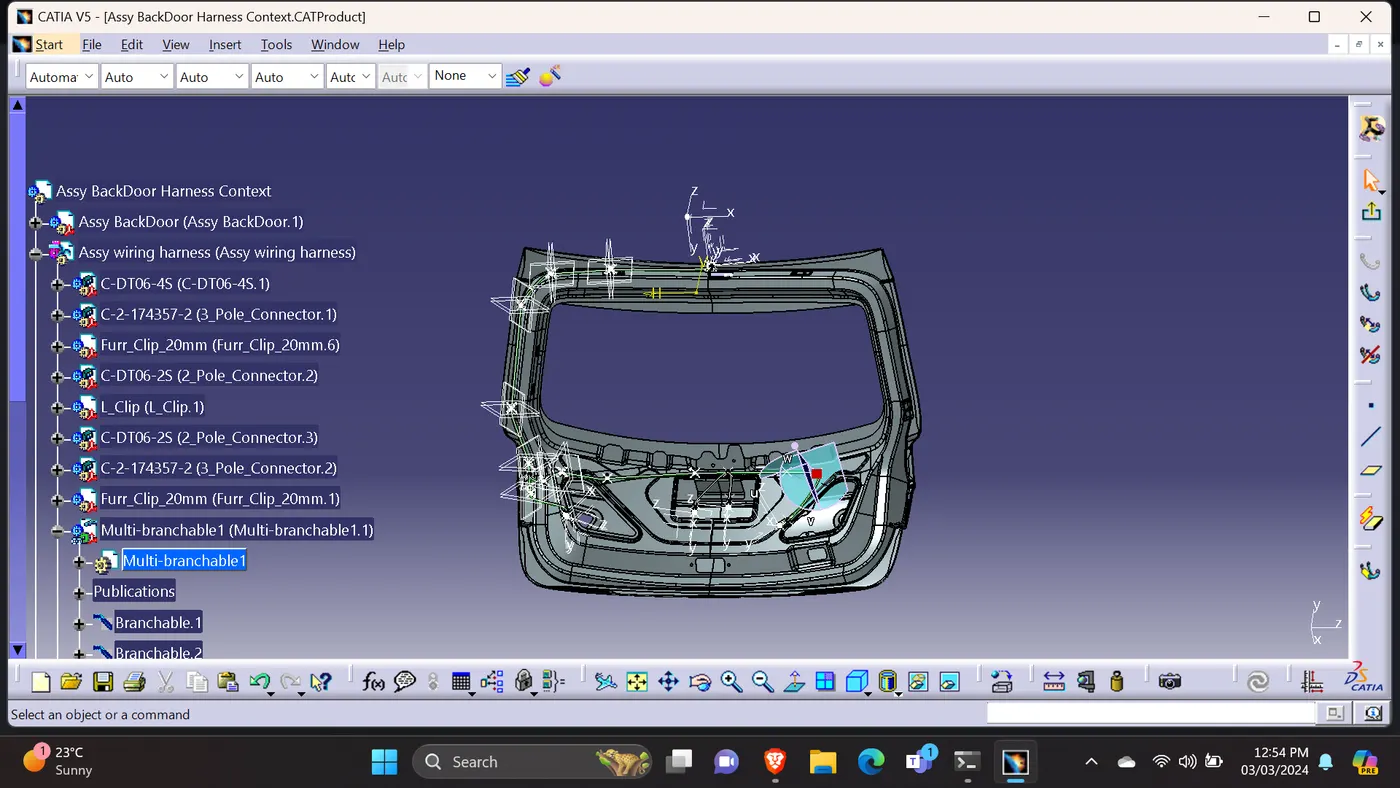
1)Downloaded the given backdoor assembly STP File & Converted into CAT Part.
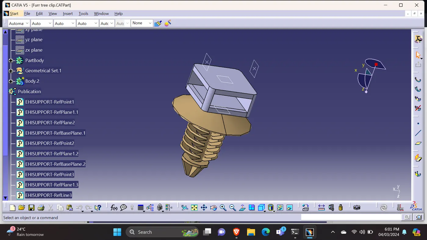
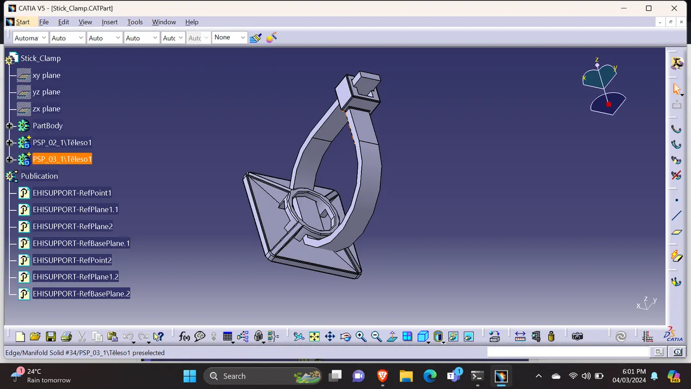
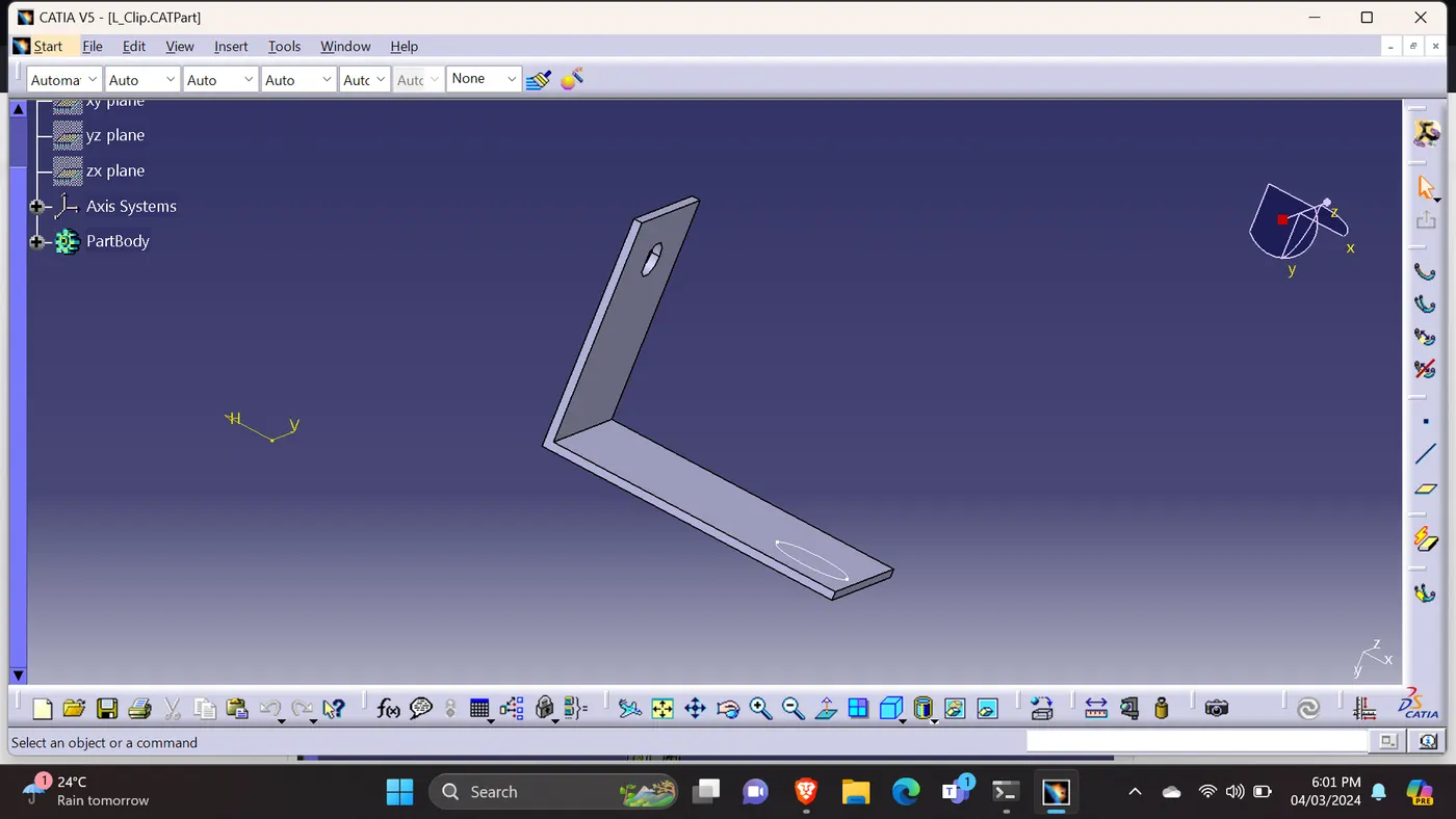
2)Used the required connectors, clips, clamps, & supported files.
3)Defined as Electrical part which are required to do.
4)Used the connectors which are used before project.
BACKDOOR WIRING ASSY CONTEXT:
CONNECTORS USED:
1)Downloaded the engine CAD part from the given question.
2)converted to CATProduct.
3)Used the required connectors to build the wiring harness.
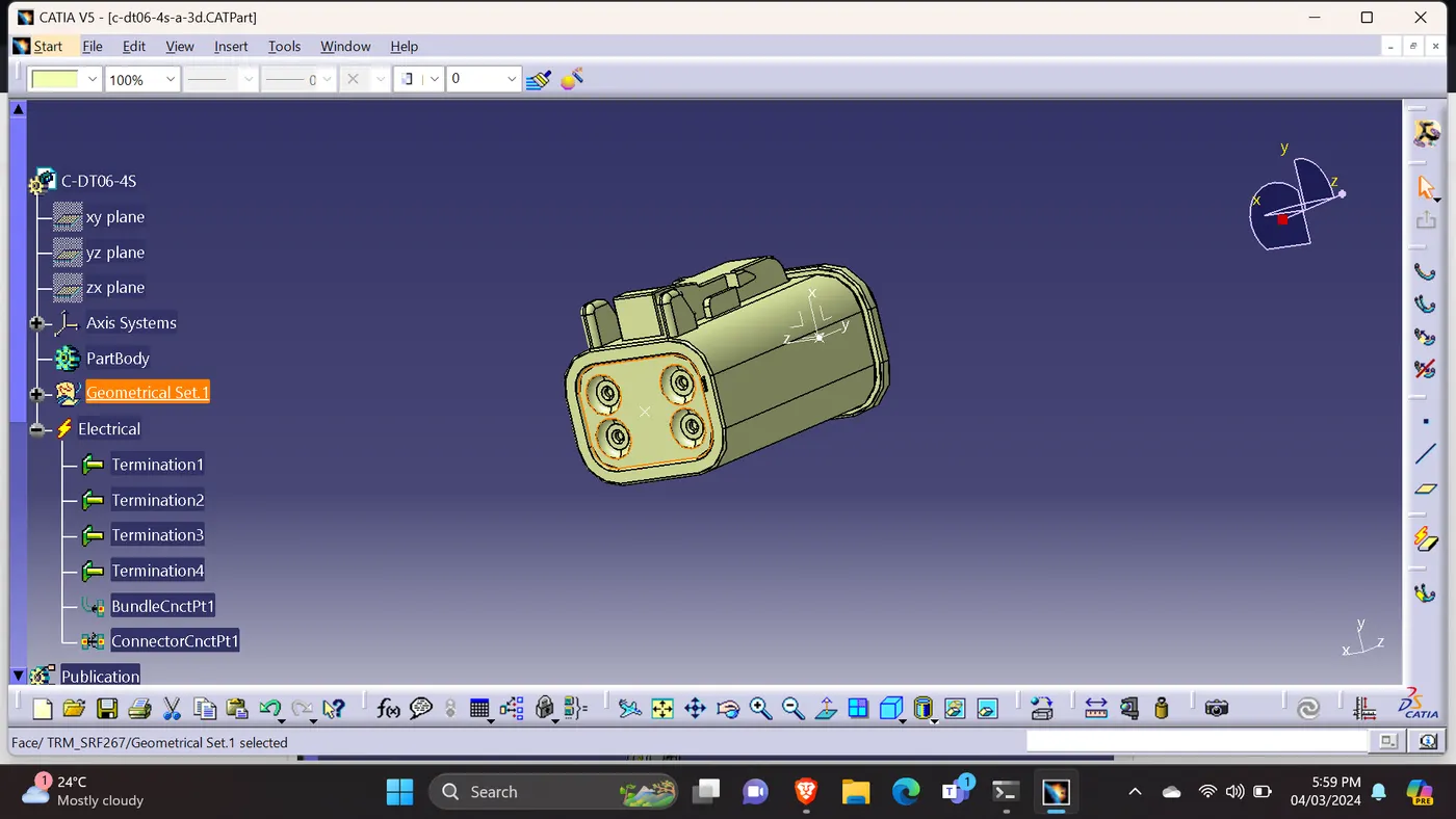
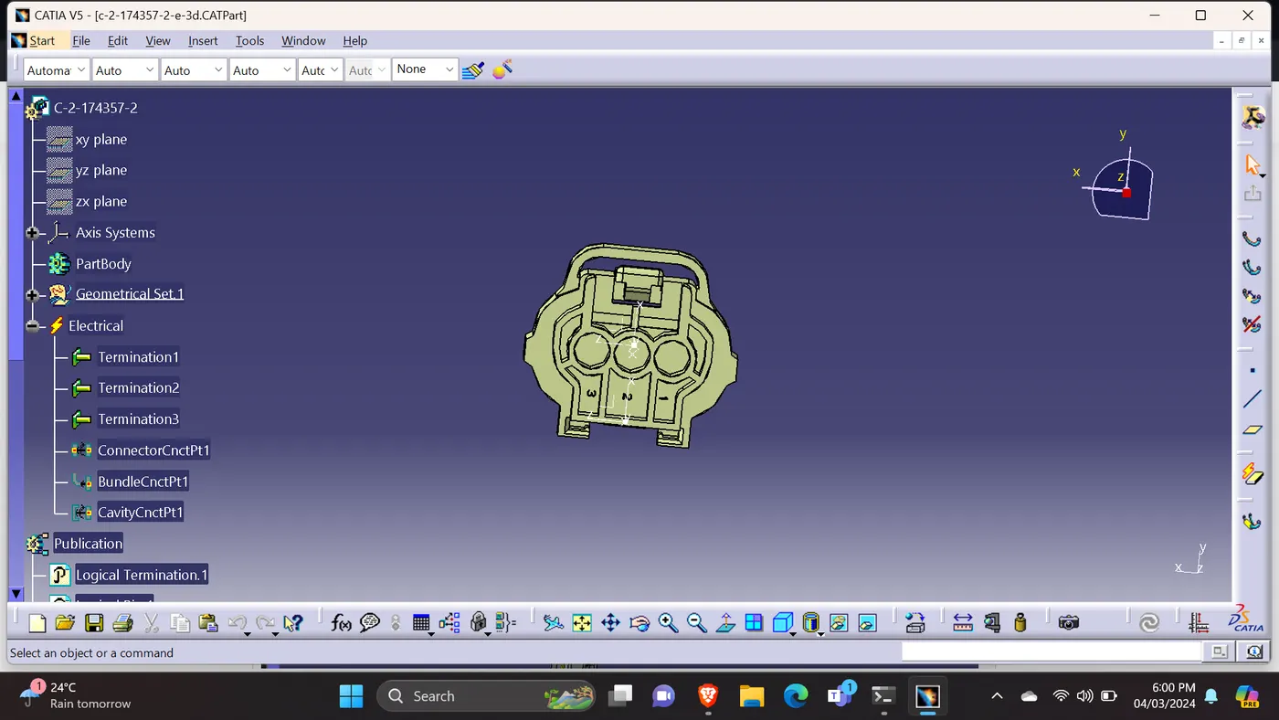
4)Created the required geometrical parameters. Defined the bundle entry point, connector connection point & cavity connection point.
5)Defined the connector part as electrical.
6)Used the 2 pole, 3 pole, 4 pole connectors.
7) Used the the CATIA manipulation, compass, snap & smart move commands to fix the connectors and the required parts at their appropriate places.
CLIPS & CLAMPS USED:
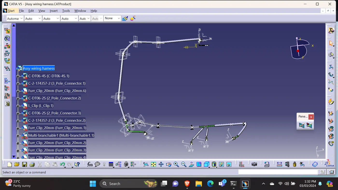
WIRING HARNESS ASSEMBLY:
1)opened the wiring harness assy in a seperate window to do the flattening.
CONTINIUNITY CHECK- TRUE & FALSE:
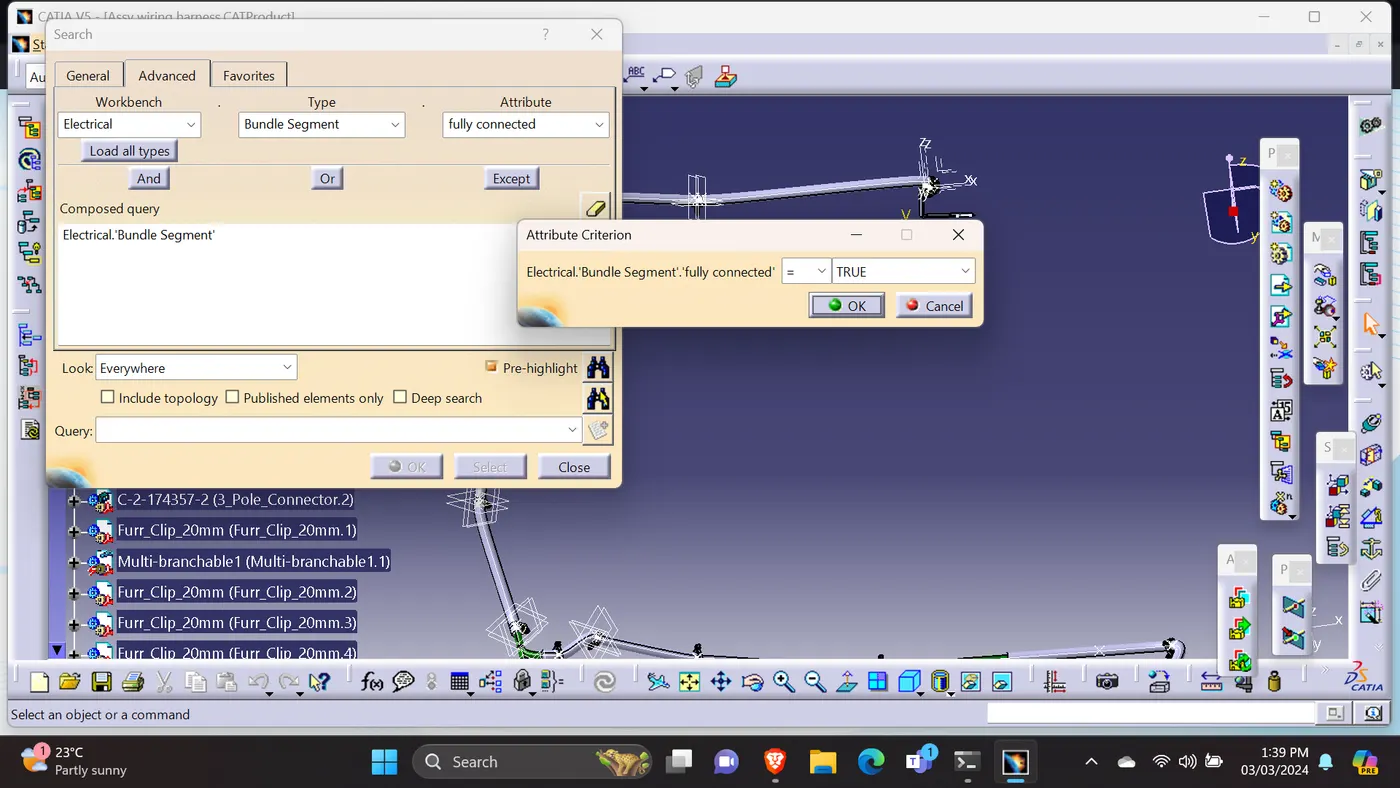
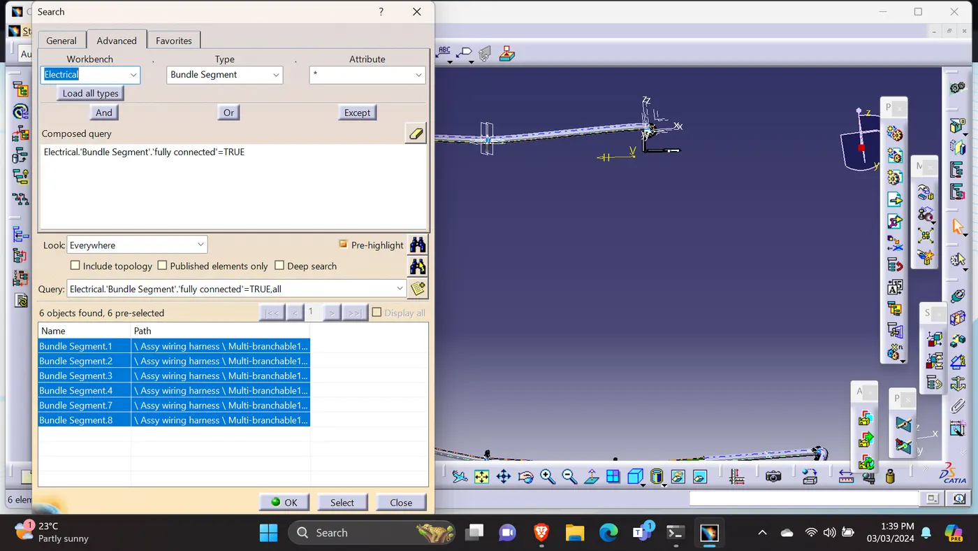
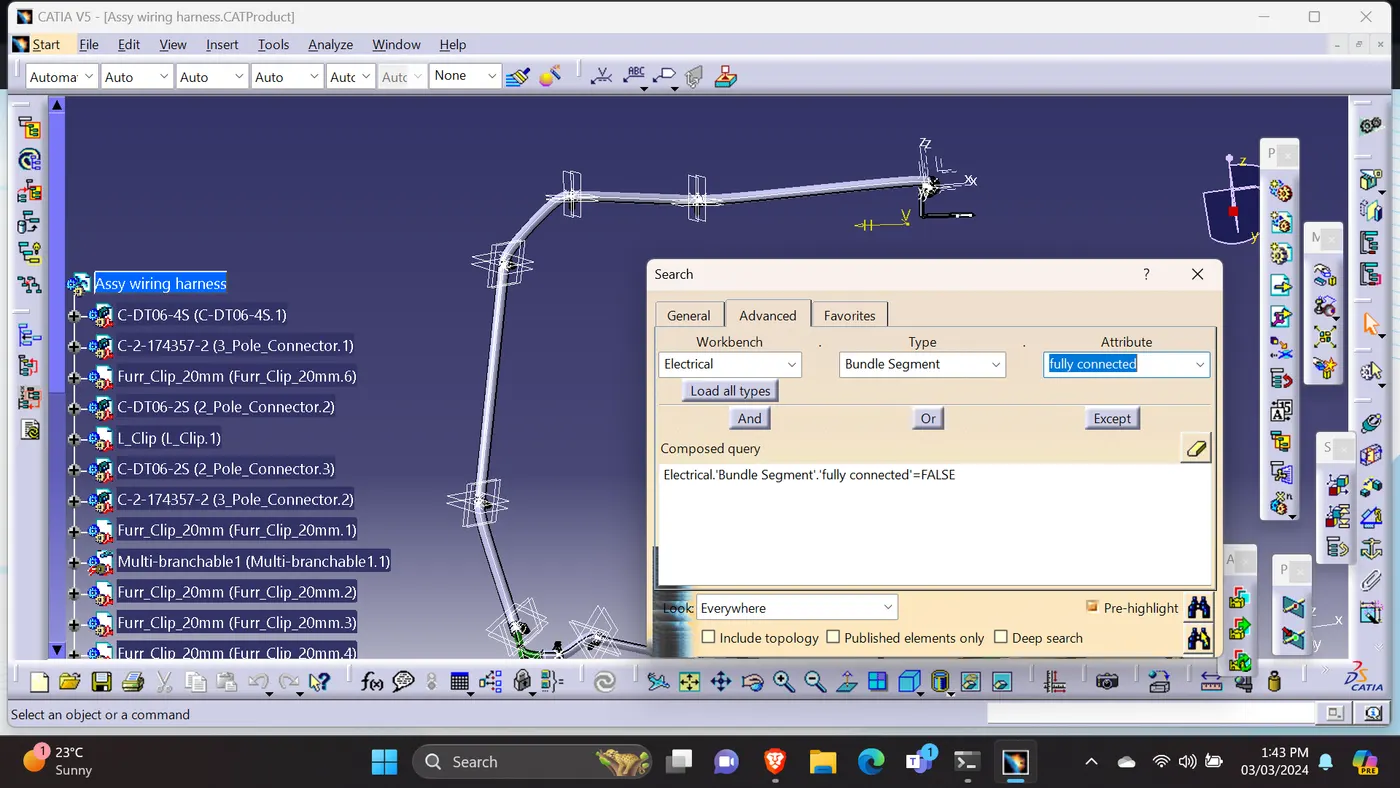
1)Once done the wiring harness assy routing, checked the continunity for the bundle.
2)Moved to assembly design workbench, went to edit, search.
3)As per the below picture table will pop-up table.
4)selected the electrical workbench, selected the bundle segment type and fully connected attribute.
5)selected the 'TRUE' & 'FALSE' option to find the continunity of the bundle.
6)Attached the screenshot.
FLATTENING:
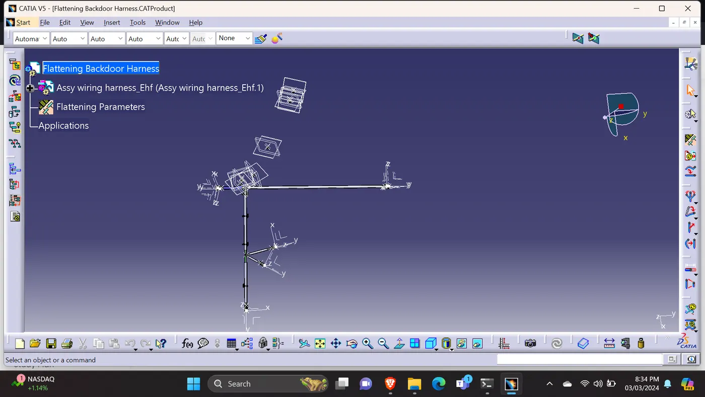
1)Opened flatten product to flatten the wiring harness file.
2)defined the all flattened parameters.
3)flattened the wiring harness.
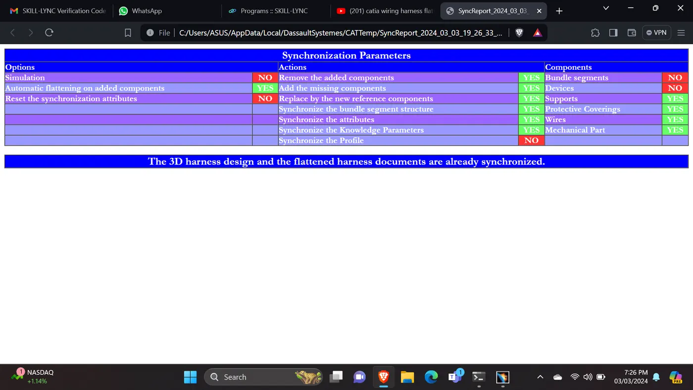
SYNCHRONIZED:
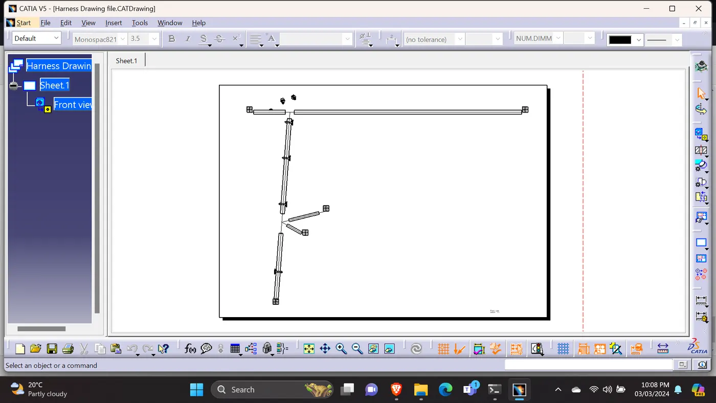
FLATTENING DRAWING SHEET:
To generate a drawing view of the harness, opened a new drawing file, selected the command 'front view', then go the flattened harness window and selected an appropriate face.
Right clicked the drawing sheet and selected the properties.
In the view tab, '3D wireframe' and 'Always visible' in the dress up settings to make the bundle segments visible.
1)Attached the necessary files (CAT Part) in the upload section.Find the attached files.
2)Attached the necessary screenshots.
2)Uploaded on Goolgle Drive. ( https://drive.google.com/drive/folders/16-GTTU5Oi8xIfIxPA9tLEShTmTSqR9RV?usp=drive_link )Attached google drive link. Find the attached files.