Project 2
AIM:
To route the Wiring harness on given car body back door and prepare flatten view drawing in CATIA V5.
Step 1- download the Back Door CAD data from the given source.
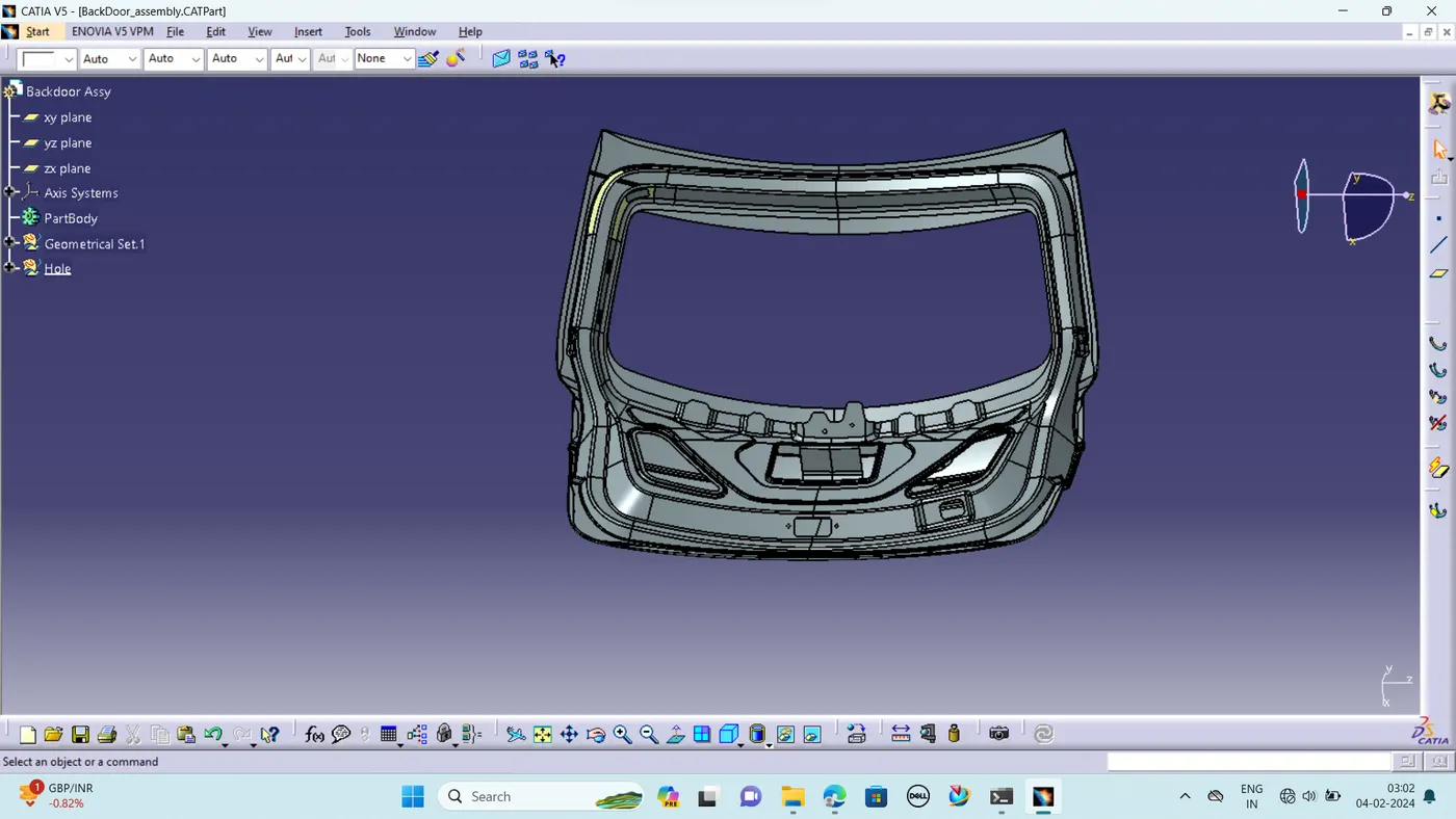
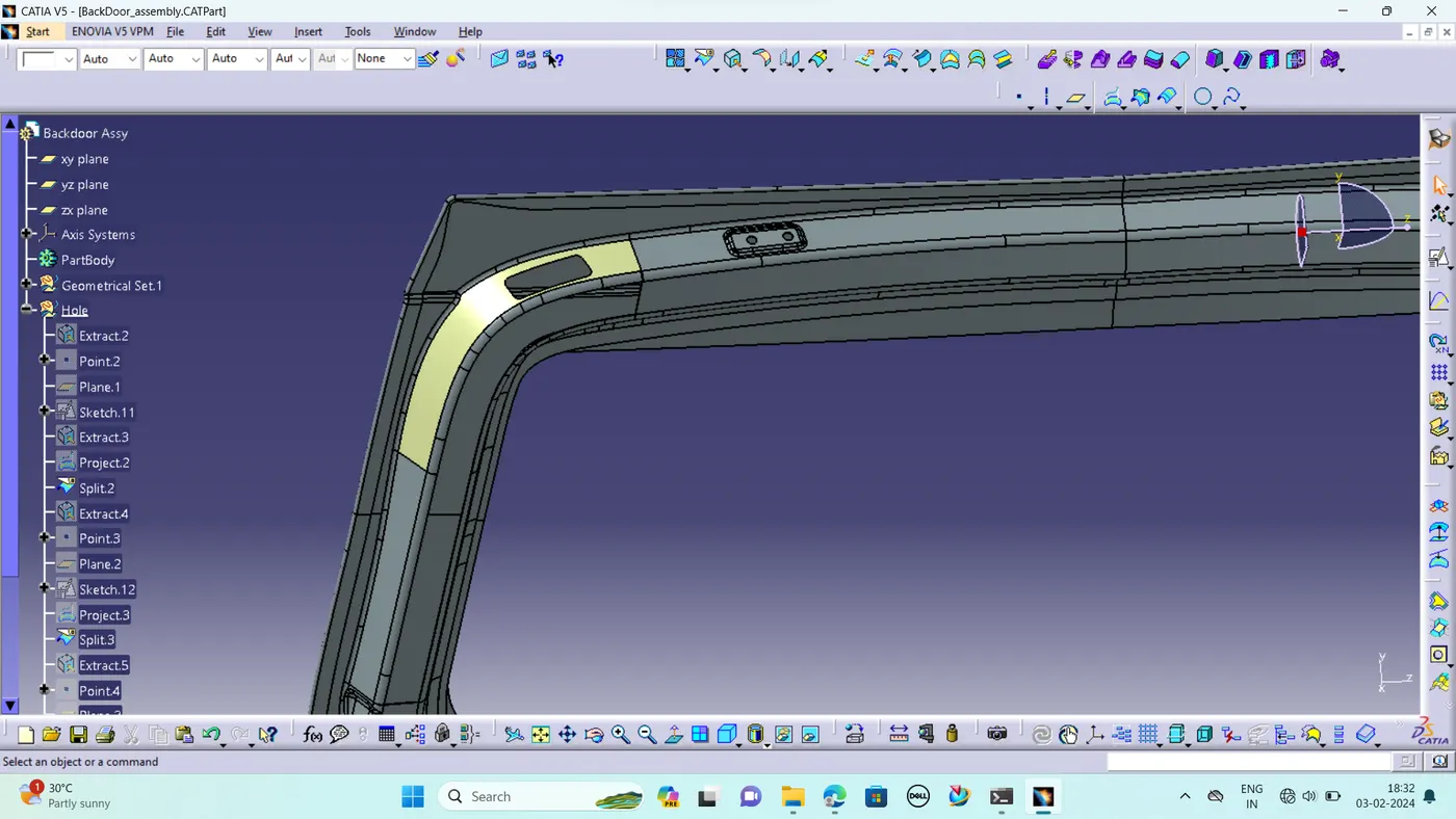
STEP 2 – Creating Holes on the given Back door data for reference purpose.
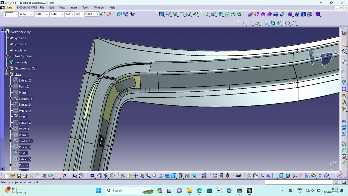
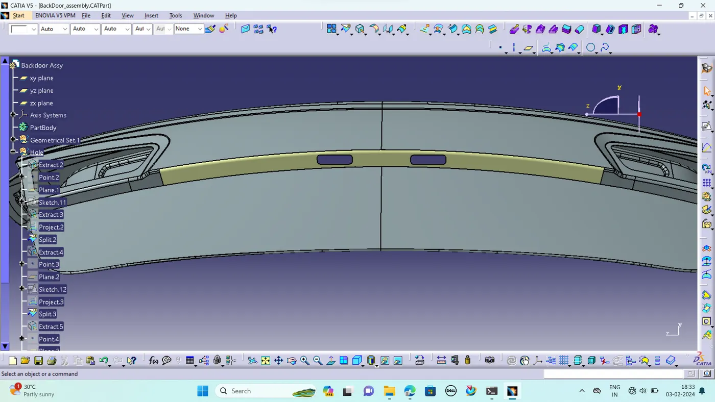
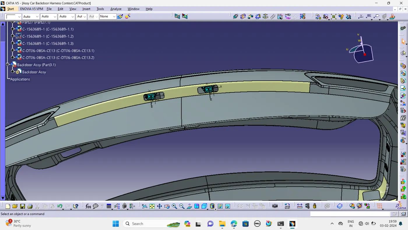
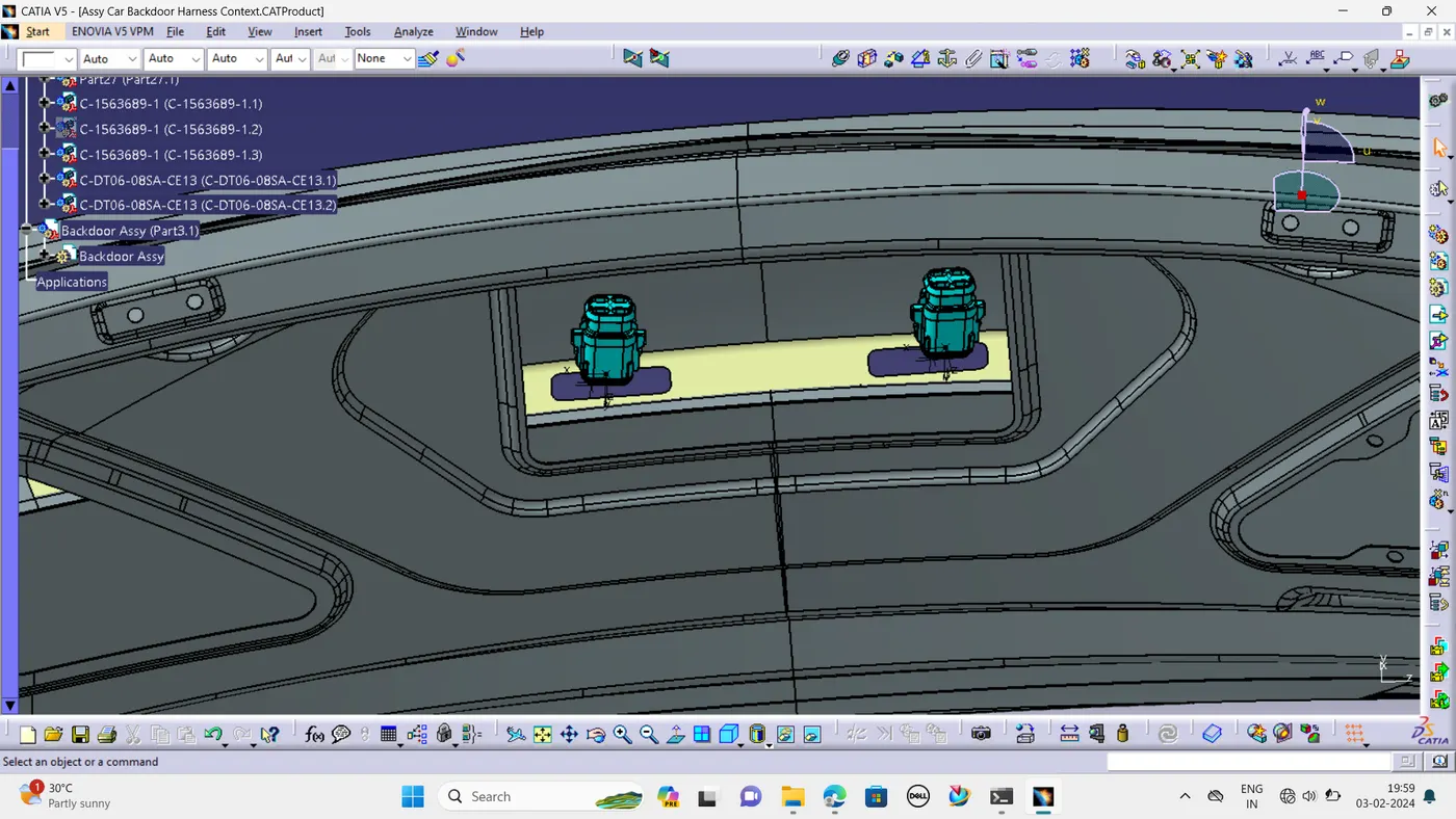
STEP 3 – Add required suitable Connectors.
Interconnection Connector:
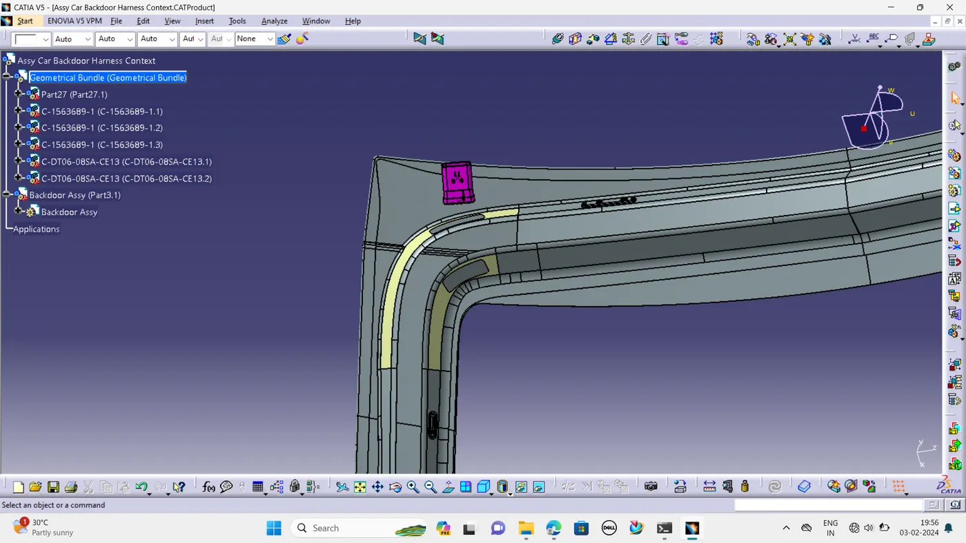
- C-1563689-1 used for Brake Light assembly connections and Wiper motor connection
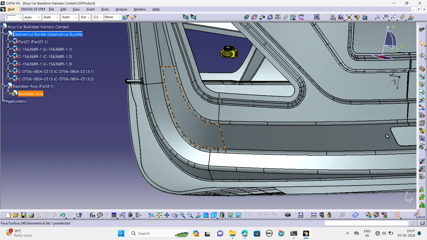
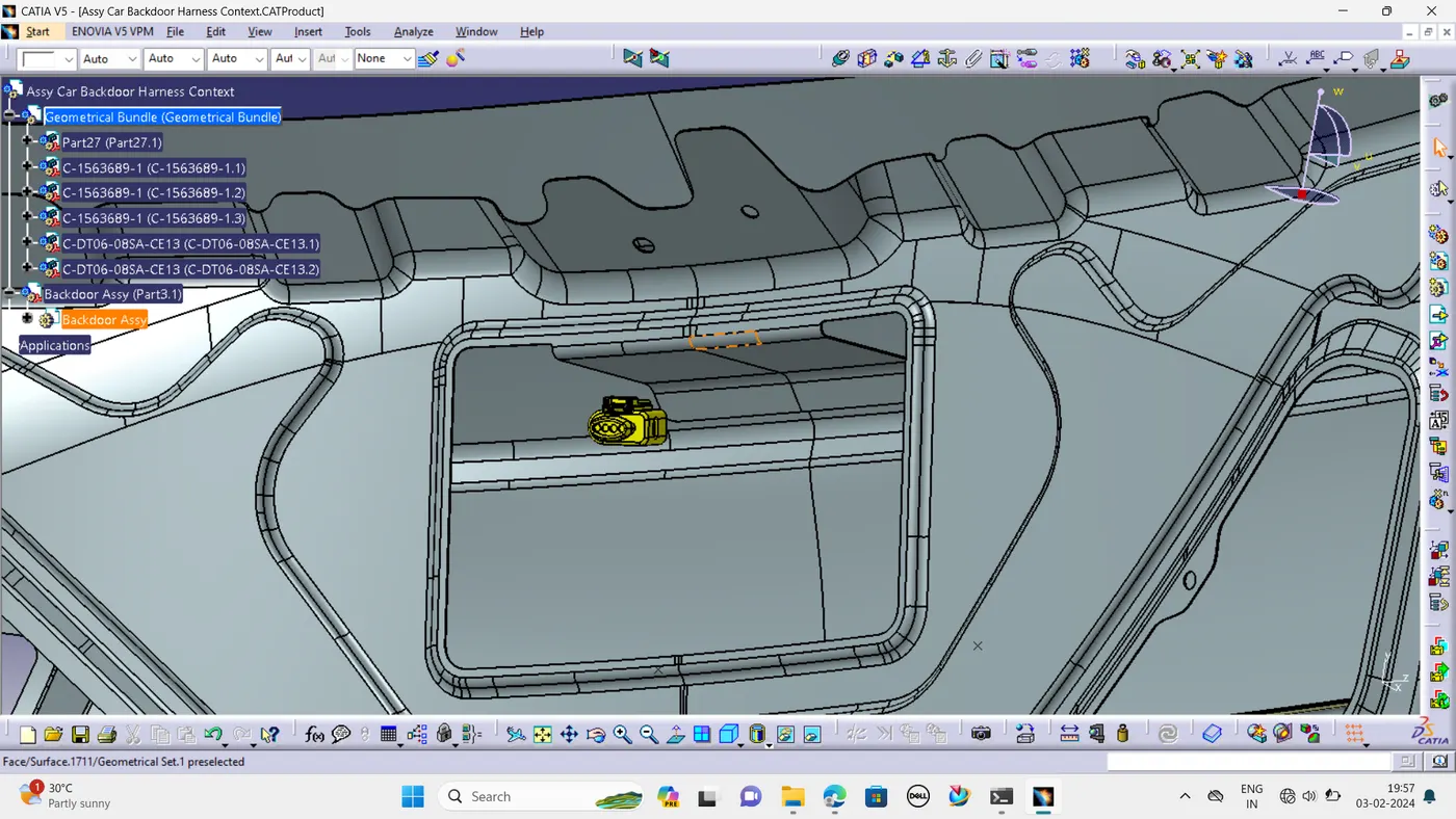
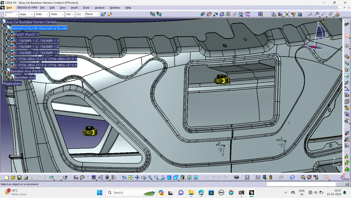
- C-282080-1 used for numberplate connections
STEP 4 – Placing fir tree clips to the required locations to ensure proper harness routing throughout the Assembly.
- Ensure no fouling of harness to the back door sheet metal components.
- Enough clamps shall be provided to ensure the positive clearance with surrounding and safety of wiring harness. Distance between two clamps/clips on a straight branch should be maximum of 200mm. However clamping requirements should be decided based on the harness bending and mounting arrangements.
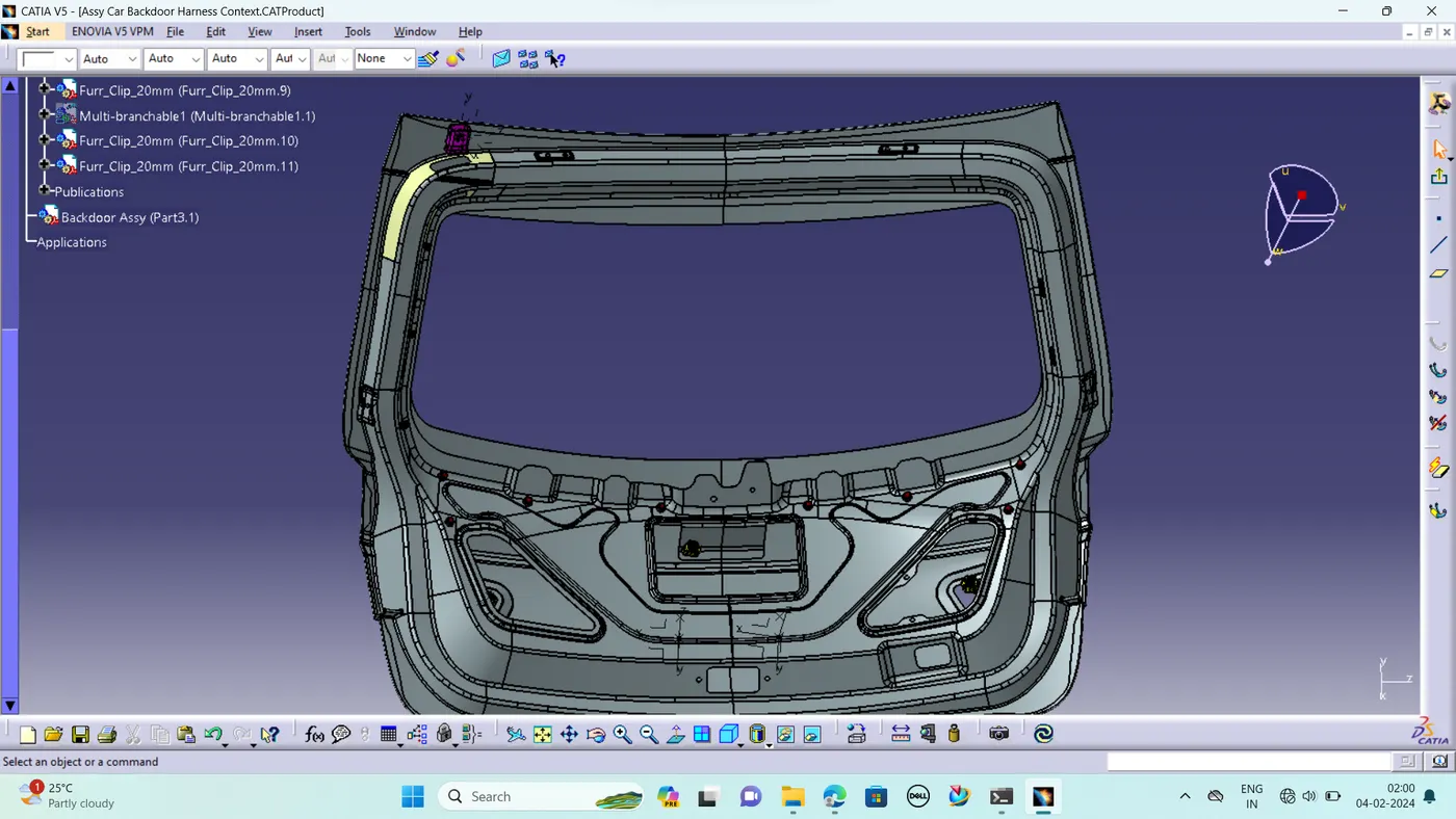
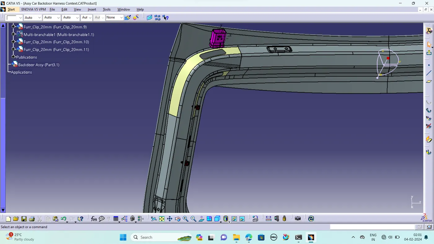
STEP 6 - Wiring Harness Routing
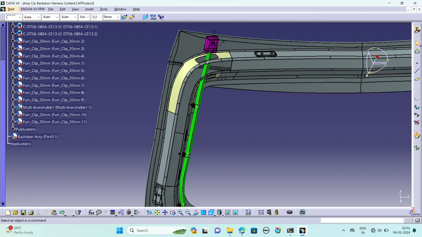
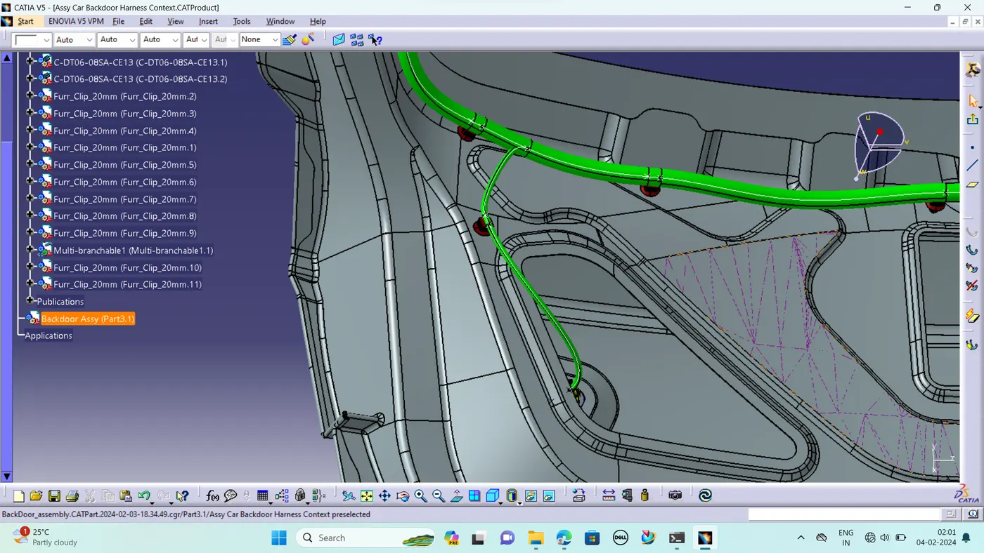
- Add branch points at minimum of 25mm distance from clips and clamps to create new sub branches connecting various connectors.
- Minimum length of bundle should be 50mm.
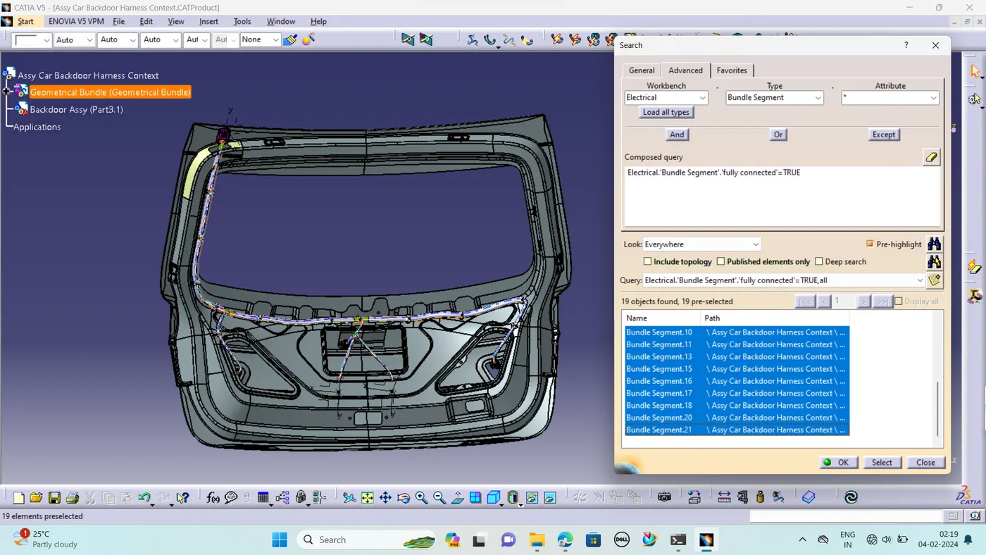
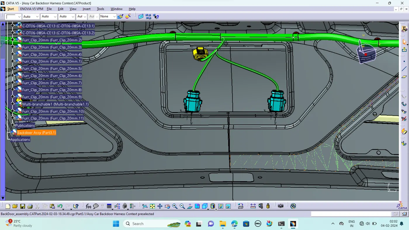
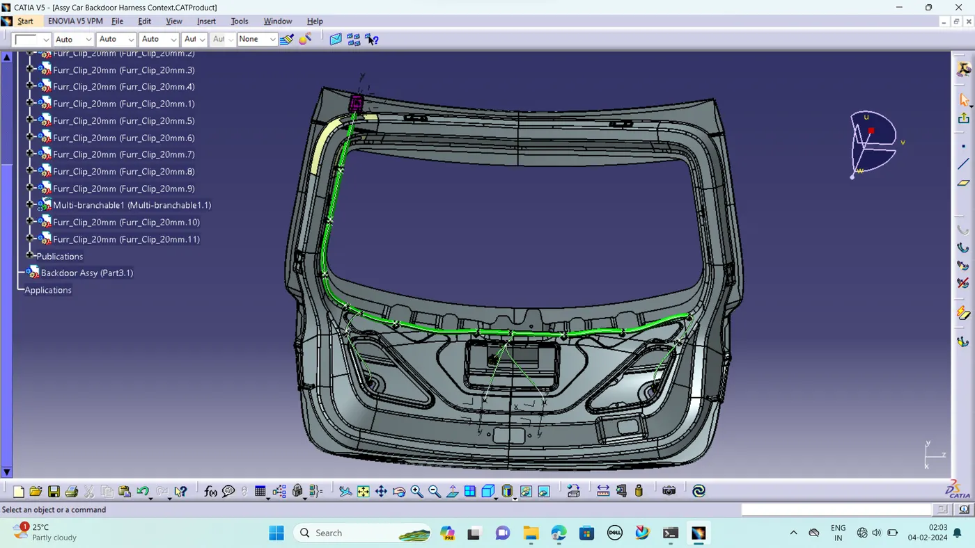
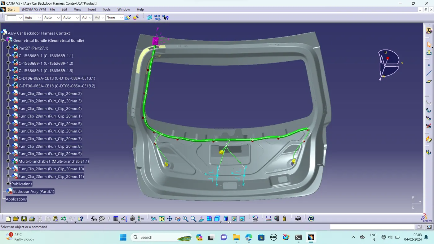
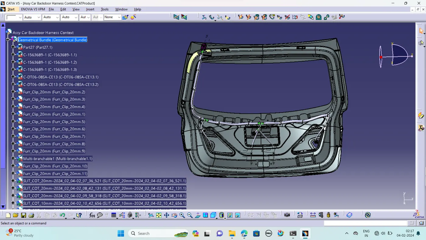
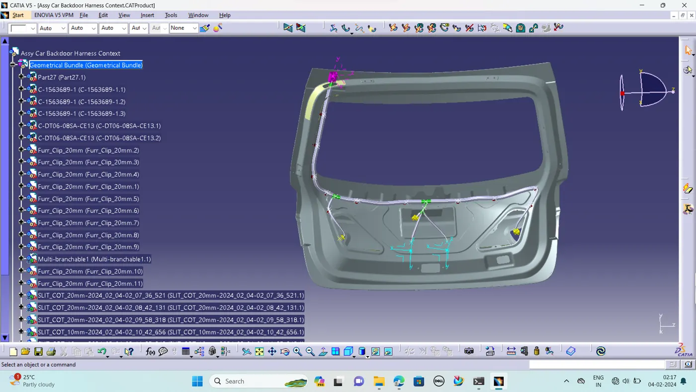
- Now, the car tail gate assembly is ready for the bundle routing as shown in below image
- We have activated Geometrical bundle product file from the context assembly to create new multi-branchables.
STEP 7 – Applying Protective Cover
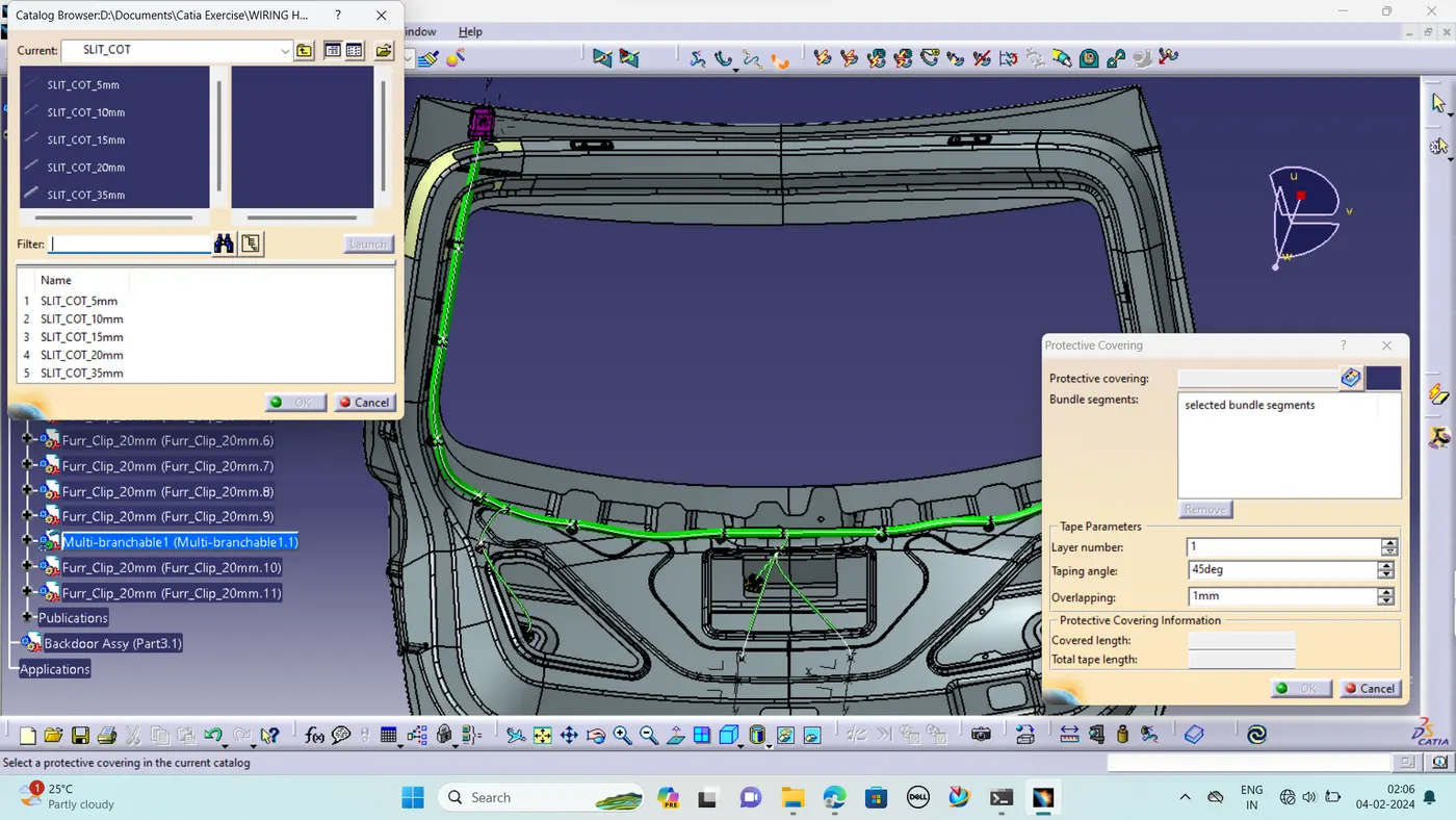
After bundle routing, we have to add protective covering to the harness bundle so that it will get protected from the damage.
- Harness bundle should be protected with flexible rubber cover at the interconnection region where it is a critical place and subjected to opening and closing of door. There are more possibilities to damage the wiring harness if no proper protection covering is provided.
- Corrugated conduits and protective hoses with various properties, from heat resistance through abrasion protection and impact strength to noise reduction, protect valuable cables against all unfavourable external influences.
- Slit COT tubes are provided for protecting the harness from physical and other environmental damages that can occur in the long run.
- Start or End Extrimities at the Connector bundle entry side should be given a gap of 30mm.
STEP 8 - ELECTRICAL CONTINUITY CHECK
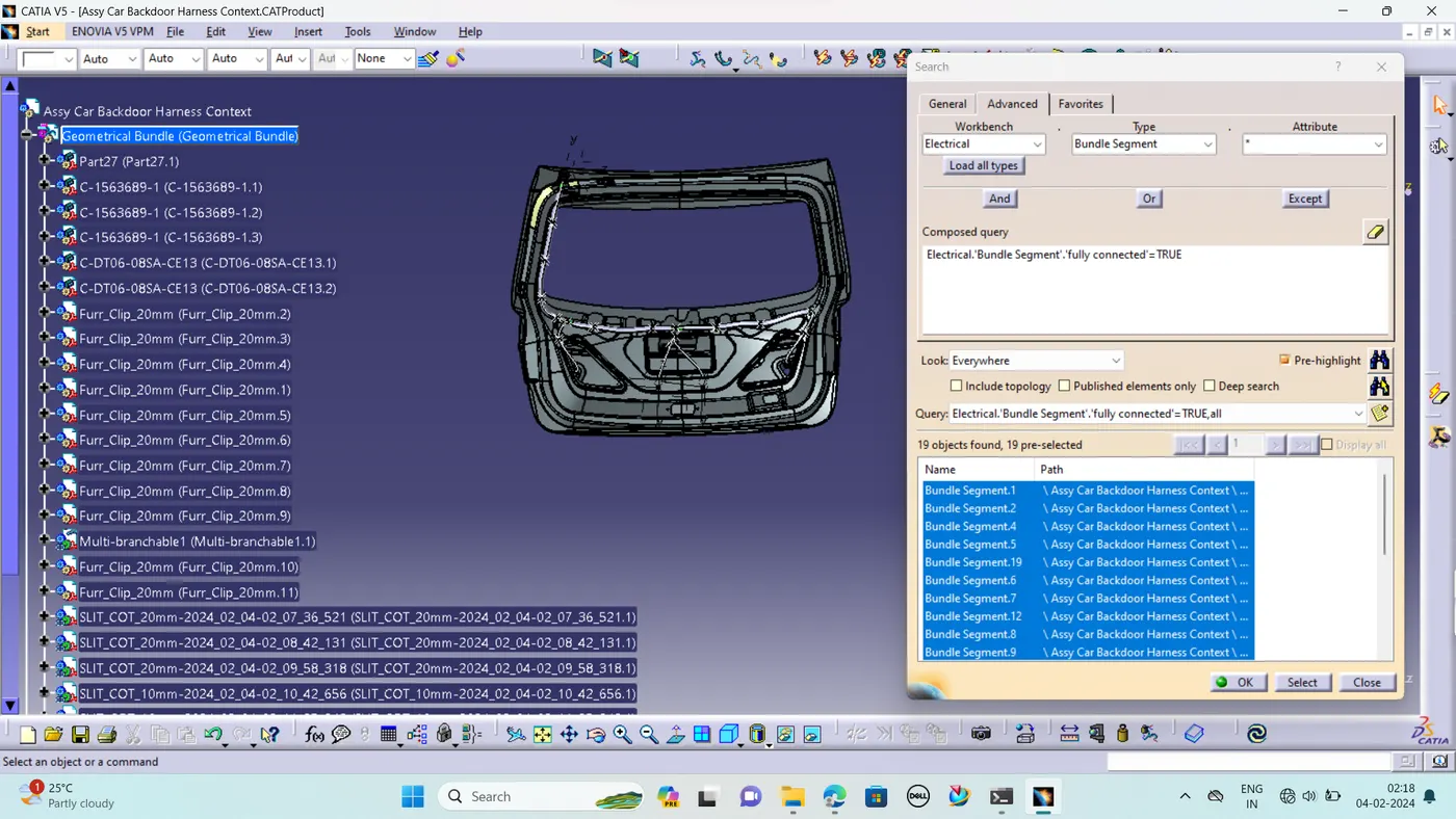
We need to ensure that the entire bundle is fully connected.
- Go to edit and then click on search command.
- Go to advanced
- Select workbench as electrical, type as bundle segment and attribute as Fully connected
- The select result should be as TRUE or FALSE and the click search to see the connectivity analysis result.