Project 2
Project 2
CPU FAN BEZEL MOLD DESIGN USING SOLIDWORKS:-
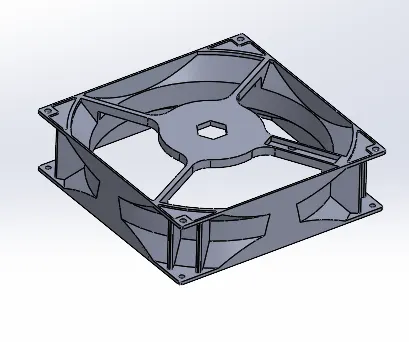
Component:
OBJECTIVE:-
To create mould for CPU fan Bezel using Solidworks having sliders, ejectors, air vents, cooling channels & all required features.
INTRODUCTION:-
Injection moulding involves heating & injecting the plastic material under pressure into a closed metal mould tool.
After the sufficient cooling cycle the material gets solidified as per the required shape.
Then the mould is opened & the required component is processed for the next usage.
Injection moulding is a manufacturing process for producing parts by injecting molten material into a mould.
Injection moulding can be performed with a most of materials mainly including metals for which the process is called die-casting
Glasses, elastomers, confections, and most commonly used thermoplastic and thermosetting polymers.
Working:
Initially the mould is made by the mould maker as per the specified dimensions of the required component with accuracy to get the good quality component.
After that the elevated temperature plastic material is poured into it & after the completion of cooling cycle the material gets solidified.
Then the mould is opened sliders & ejector pins are removed.
The given component is ejected out after all this process.
Methodology:
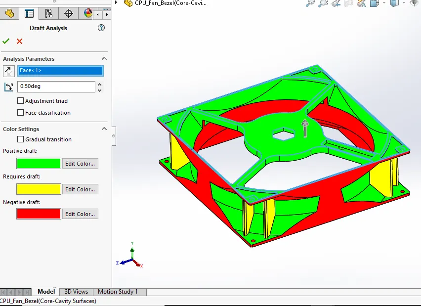
Step_1: Draft analysis
Draft analysis is executed to make sure the sufficient drafts are given to the given component. If sufficient drafts are not given then there will be problem occurs at the removal of the solidified component. The components where draft is missing is applied in this step & then the draft analysis is conducted again at 0.5 degrees.
Step_2: Scaling
Every material having some shrinkage properties. To cater with the shrinkage problem the scaling allowance is provided for the materials. In this project the ABS material is used which is having shrinkage allowance of 0.6%.
(0.6/100)+1=1.006 is the scaling provided to the given component.
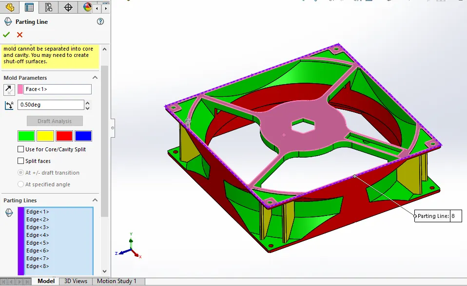
Step_3: Parting Line
The parting line divides the core & cavity into two parts.
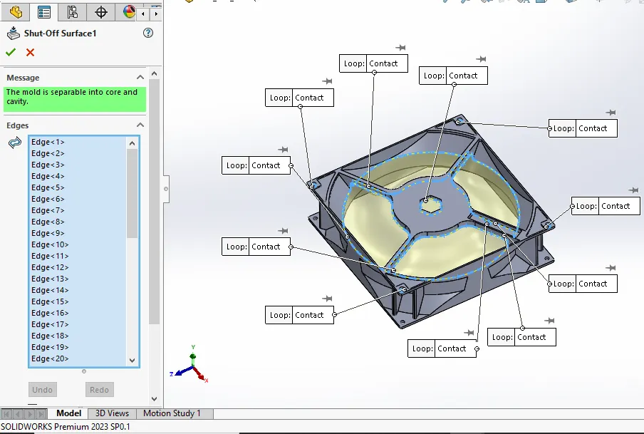
Step_4: Shut Off Surfaces
Shut off surfaces command is used to cover the holes in the given component. The hole should be covered to divide it into core & cavity. The tangent type of shut off surface is used at irregular surface.
Step_5: Parting surface
The parting surface command is used to create the parting surface for the given component.
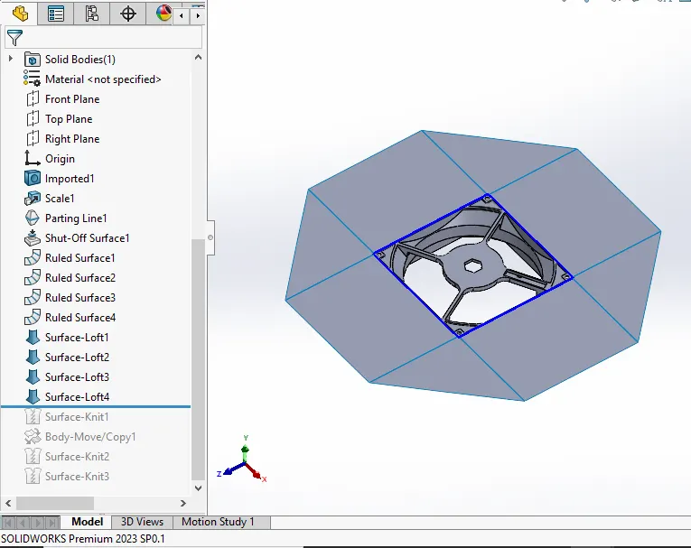
Step_6:creating core cavity surfaces
The copy of the parting surface is created using move/copy command from direct editing
Then the knit surface command is used to get the two different surfaces as core surface & cavity surface.
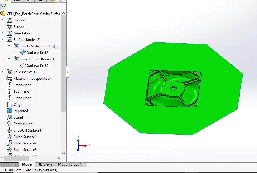
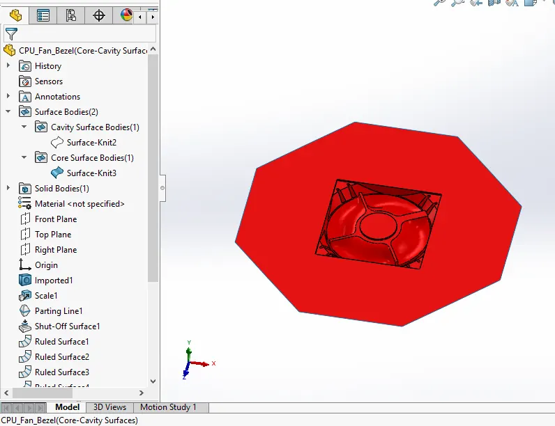
Step_7:Open core cavity in assembly.
Step_8: Core block creation
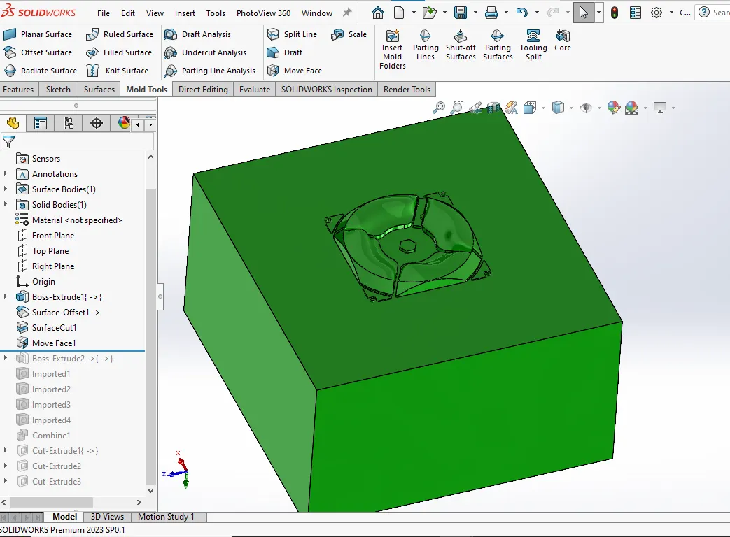
The rectangle is drawn on the core surface & it is extruded to get the core block.
Then the cut with surface command is used to get the core block.
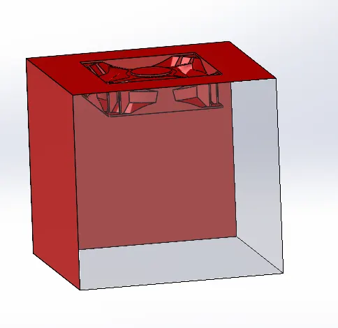
Step_9: Cavity block creation
By using the previous core block sketch is used using convert entities command & then extruded.
Then by using cut with surface command we can get the cavity block.
Step_10: Ejector Pins
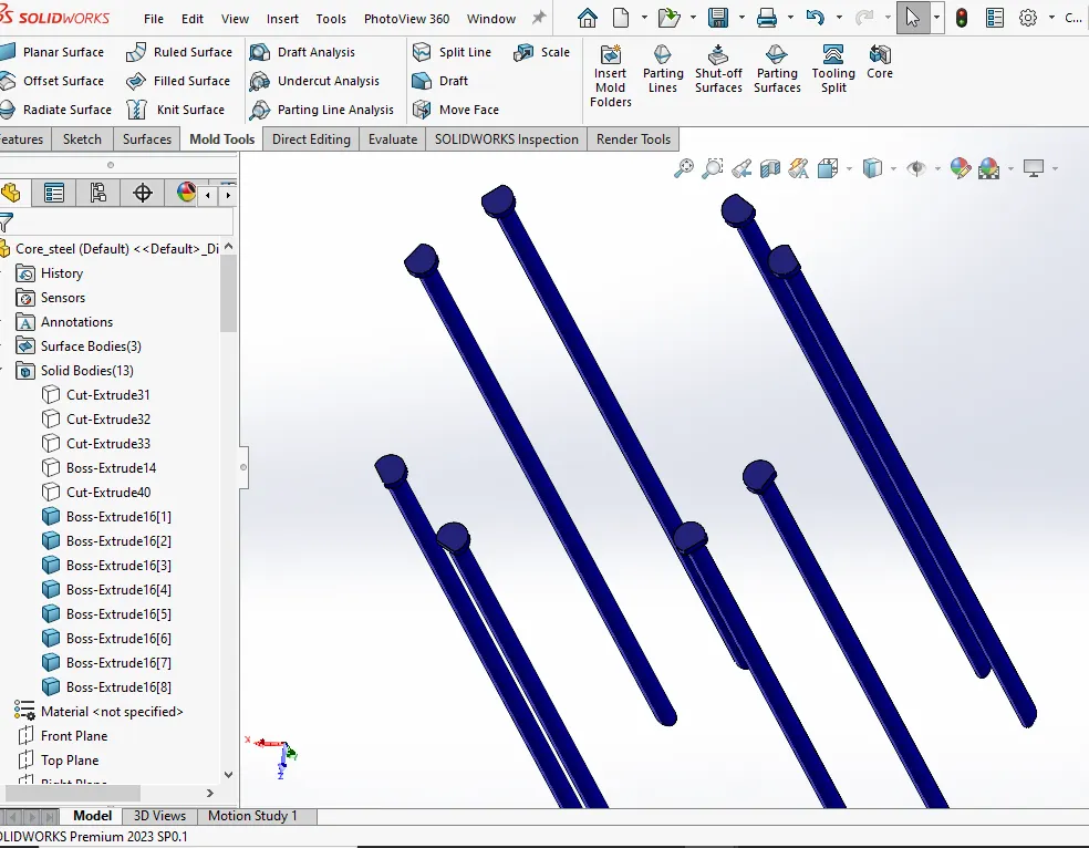
Ejector pins helps the component to be removed safely from the mould when the part has cooled down.
Step_11: Created reliefs for the ejector pins.
for 6mm ejector pin relief should be provided after 10mm and relief diameter for 6mm pin is taken as 6.95.

Step_12: Sliders
Undercuts present in the components creates problem for the ejection of the part from mould.
For the easy removal of the component the sliders & inserts are provided for the mould.
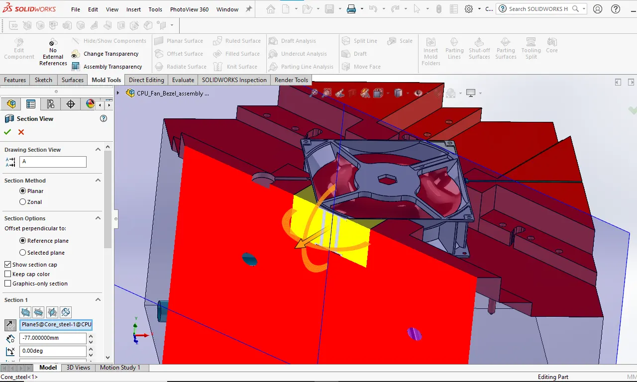
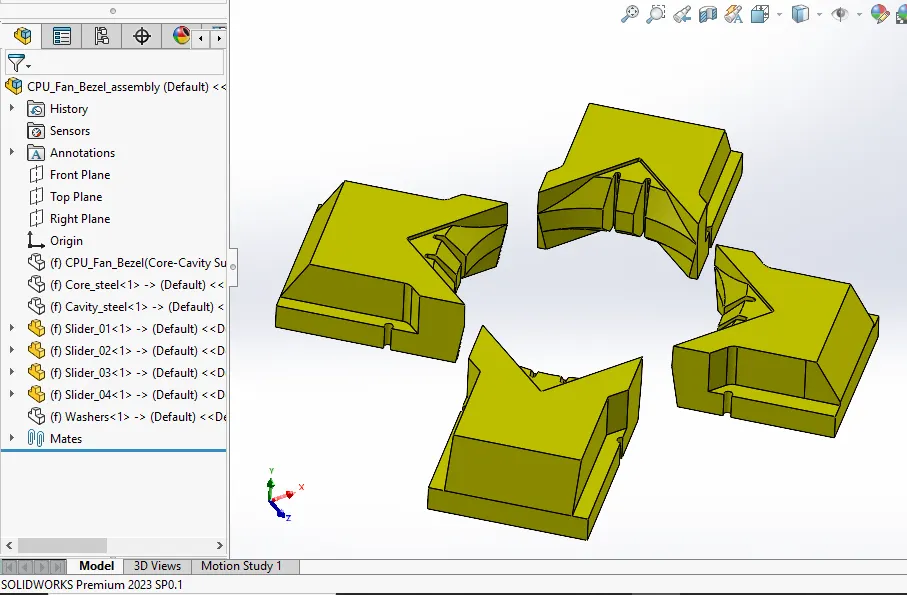
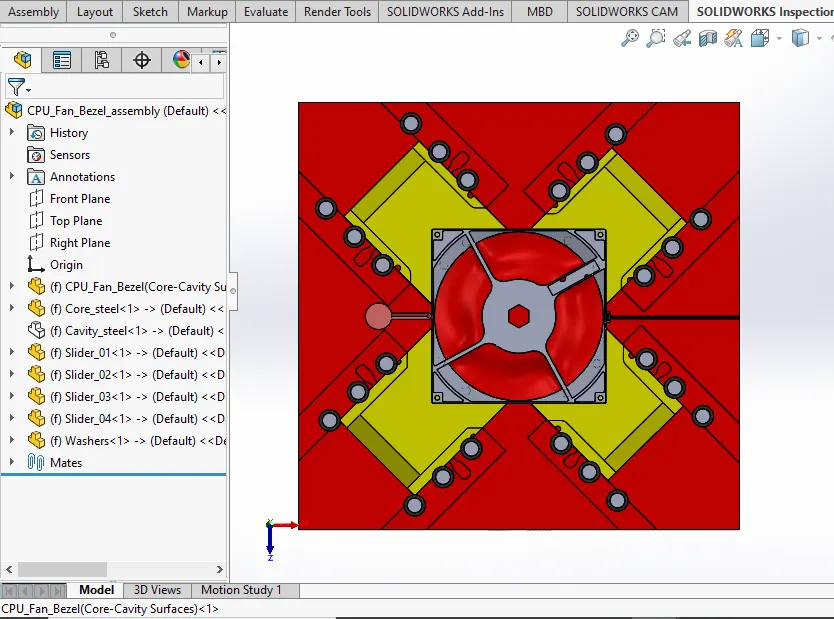
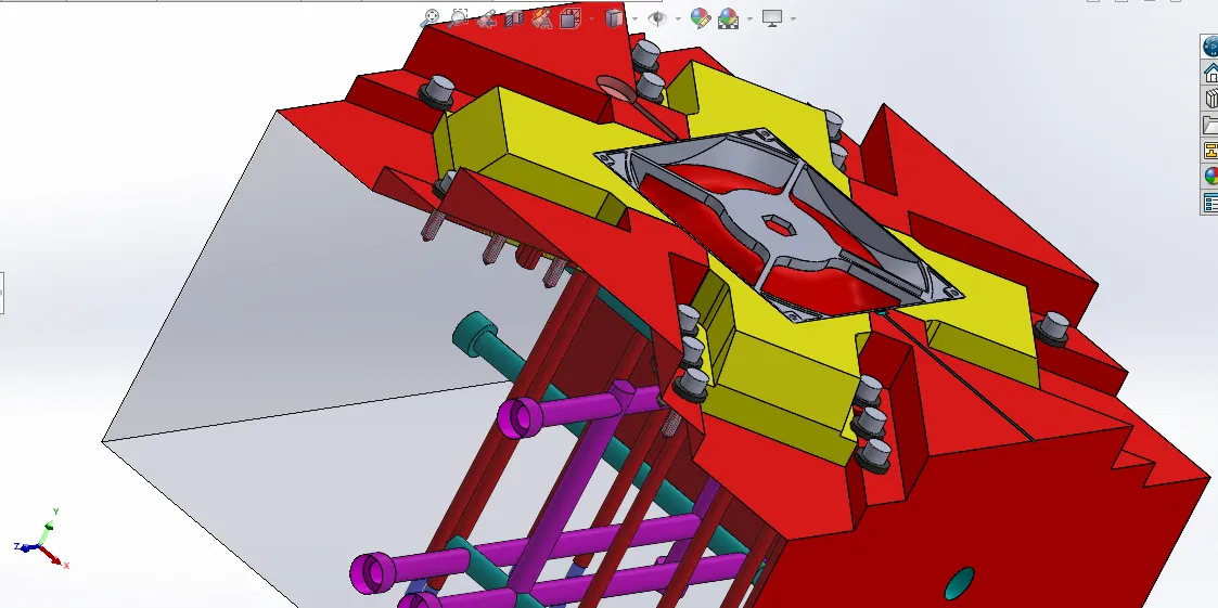
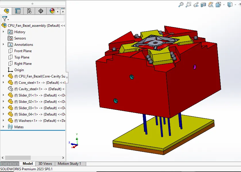
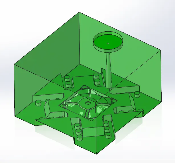
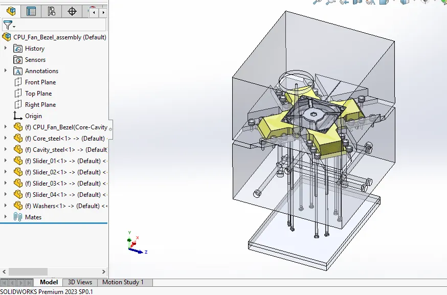
There are some features present in the CPU fan Bezel which causes problem for part ejection so we have provided four sliders at four corners of the core block which solves the undercut issue for the given part.
The sliders are created using the split command & creating the sketch of the required shape of the slider.
The wedge is provided on the slider part for the required shape.
The path is provided for the slider in the core block using the sketch & extrude cut command.
The extra material is provided in the cavity block for the vacant shape created after the slider shape creation.
Then the sliders inserted in the cavity part & the combine command is used to get the slider shape in the cavity part.
Step_13:- Washers & Blots
Washers are created on the core block combining the core block & slider.
Step_14:- Locking Mechanism
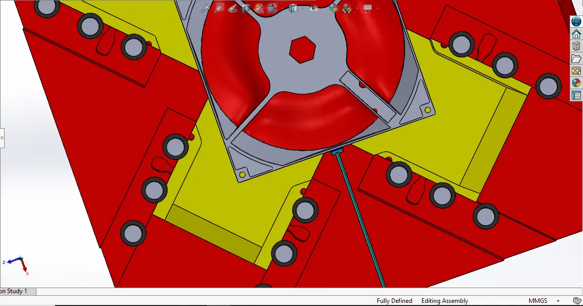
We have provided the locking mechanism to lock the slider after travelling specific distance.
The locking mechanism is created using the sketch & extrude cut command.
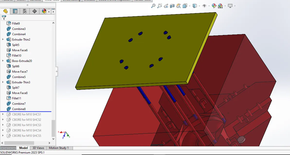
Step_15:-Ejectors
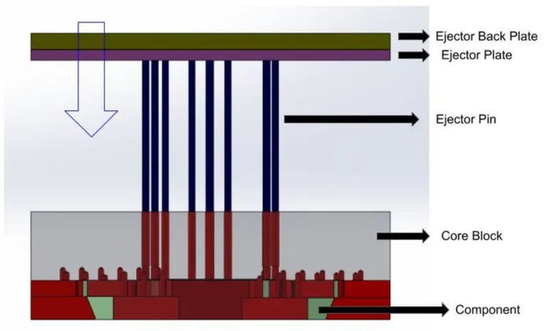
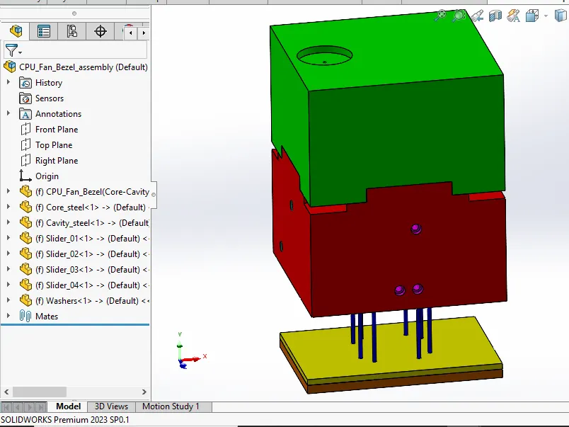
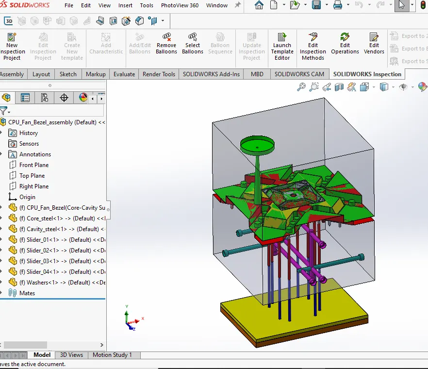
For the ejection of the given mould part the whole assembly of the ejector pins will have to move in the upward direction of the core part of the mould.
This action of upward movement completely ejects the given component present in the mould.
Ejector Pins:-
Ejector pins are created to push the part out of the mold when it is cool down completely.
Ejector pins makes the connection between the ejector plates & the given part.
The sketch created for the ejector pins & then the split command is used to create pins as a separate part from the core part.
Then the relief is provide for the smooth motion.
The D-shape pin heads are provided since the base is inclined.
Ejector Plates:-
The ejector plate & Ejector back plate is provided with 10 mm & 15 mm thickness. The slot of D- shape pin head & relief is provided in the ejector plate.
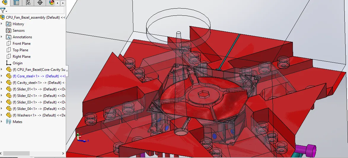
Step_16:- Runner & Gate
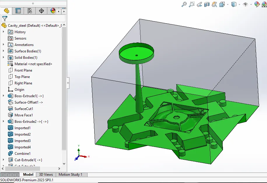
Initially the sprue is created in the cavity part having tapered hole throughout.
Then the 5mm deep cut of tapered hole diameter is created in the core block.
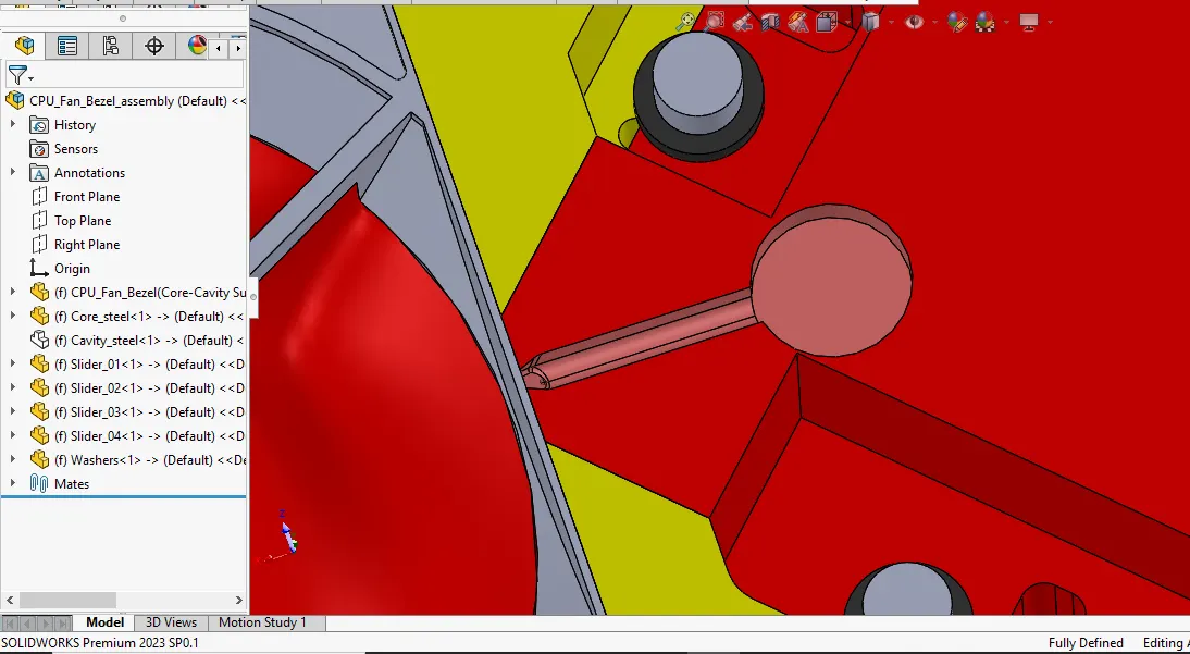
Then the trapezoidal runner is created using the extrude command. Then the drafts & fillets provided on the runner.
then the gate is designed using 40 degree draft after the extrude.
Then the runner & gate is added using combine command.
Then the runner & gate combination is subtracted from the core block.
The molten metal travels from sprue to the runner then into gate afterwards it travels towards the mould cavity.
The gate leaves a surface blemish on the part.
It is small and designed to be freeze before the part, runner or sprue freeze.
Sprue pullers are provided so that sprue comes out along the core block in the downward direction.
Runner Diameter Calculation:-
D=(W^1/2*L^1/4)/3.7
Where, D is the runner diameter in mm
W is part weight in gm
L is runner length in mm
In this Project , We have created the trapezoidal runner with the draft of 10 degrees on all sides of the runner.
Step_17:-Air Vents
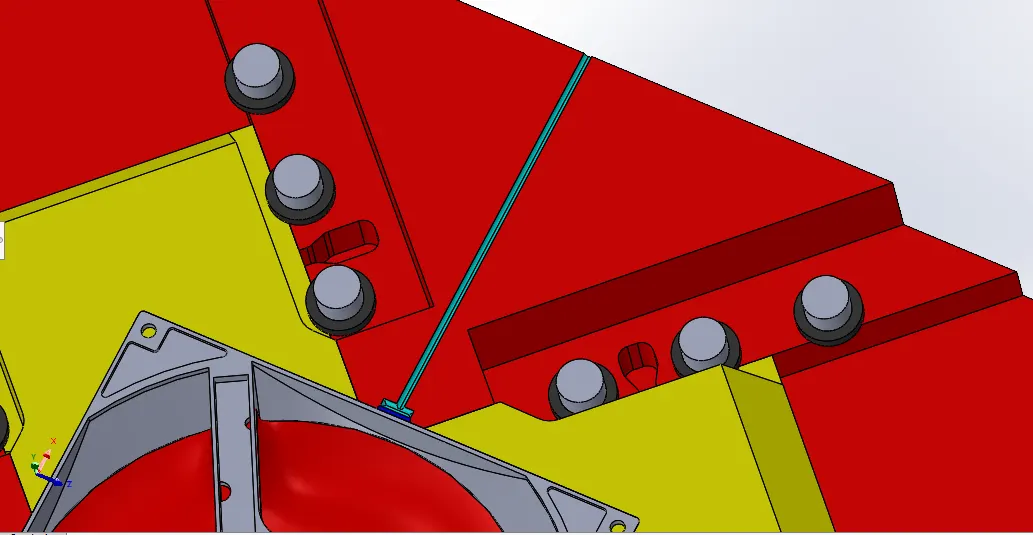
Air vents are the small channels provided in the mould blocks for the easy escape of the air.
As the moulding operation is cyclic process so in consecutive actions the air entraps in the cavity.
To provide pathway for the entrapped air the air vents are provided.
To avoid the defects in the product due to entrapped air the air vents plays crucial part in the mould design process.
Step_18:-Cooling Channels
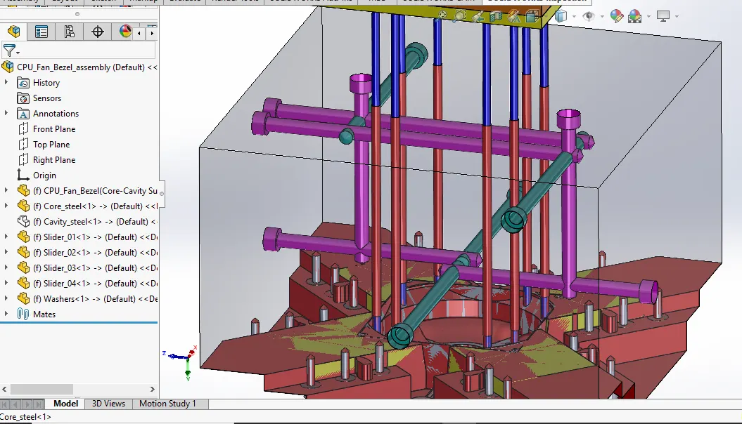
To avoid the warpage defect we provides the cooling channels for the uniform cooling in the mould.
Warping (or warpage) is the deformation that occurs when there is uneven shrinkage in the different parts of the moulded component.
The result is a twisted, uneven, or bent shape where one was not intended.
Causes: Warping is usually caused by non-uniform cooling of the mould material.
Final Mould:
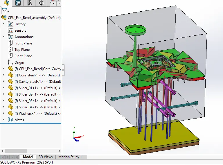
Result:-
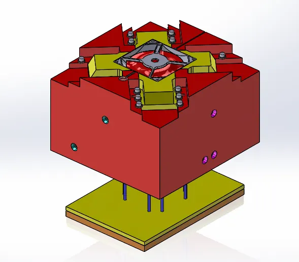
Creation of sliders, inserts for undercuts.
Ejector system to eject component.
Air vents for entrapped air.
Cooling channels for avoiding warpage.
Sprue ,runner & gates for proper travelling of molten metal.