Project 2
Objective: Establish the wiring harness routing for the designated vehicle body and generate a flattened view drawing in CATIA V5. The design will incorporate all relevant packaging rules and industry best practices acquired during this course. Implementation of protective coverings as needed is crucial.
Utilize existing 3D data of connectors, or alternatively, access connectors from www.te.com.
Compile and present comprehensive reports encompassing clearance, selection of clipping/clamping mechanisms, harness fixation specifications, harness continuity, and any assumptions made. Accompanying these reports, submit the CATIA 3D data for review.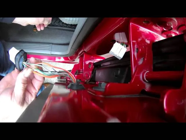
Introduction:
Car tailgate wiring encompasses the electrical systems responsible for interconnecting various components situated in the tailgate of a vehicle. This intricate network facilitates the power supply and control of essential features housed within the tailgate, including rear lights, license plate lights, rear wipers, rear defoggers, power locks, and other electronic functions associated with this section of the vehicle.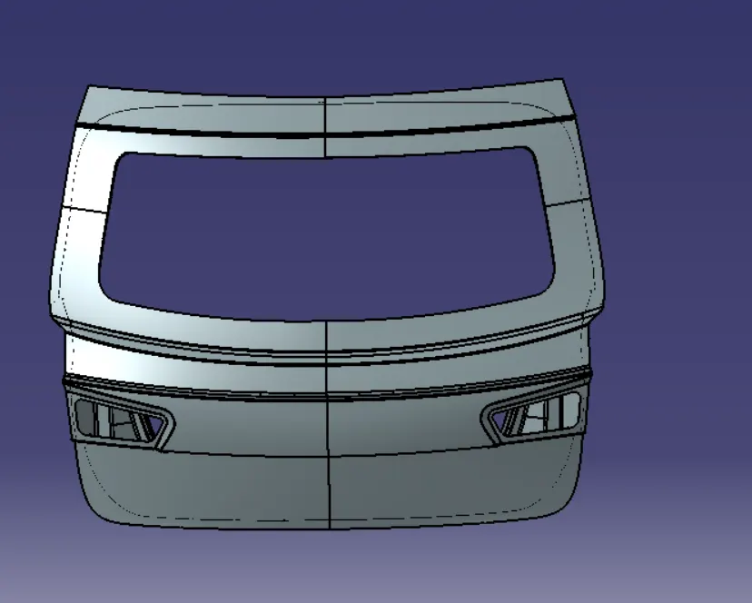
Key Components and Functions in Car Tailgate Wiring:
1. Tail Lights: The tailgate wiring comprises a wiring harness connecting to the rear lights on the tailgate, including the brake light, turn signals, and reverse lights. These lights play a crucial role in ensuring proper visibility to other drivers, enhancing overall safety on the road.
2. License Plate Lights: A dedicated wiring circuit is allocated for illuminating the license plate, enhancing visibility in low-light conditions. Typically located on the tailgate or its handle, these lights contribute to the vehicle's overall safety and compliance with regulatory requirements.
3. Rear Wiper: The tailgate wiring incorporates essential electrical connections to power and control the rear wiper motor. This functionality enables the efficient clearing of the rear windshield, contributing to improved visibility for the driver, especially in adverse weather conditions.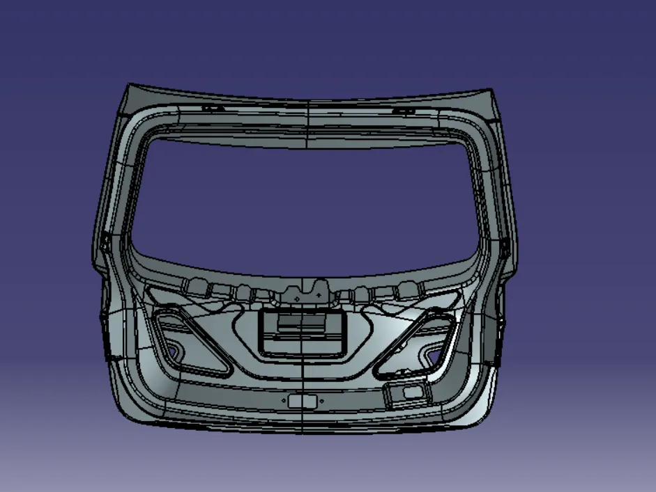
Assumptions:
1. Clips/Clamps will be provided as per specific requirements, and additional ones may be used to prevent any potential fouling issues.
2. Ensure the design prevents any fouling cases within the wire harness, and employ extra clips/clamps as necessary to mitigate such scenarios.
3. Allow for additional slack in the wire harness, ranging between 5-15% to accommodate potential movement or adjustments.
4. Avoid routing the harness over sharp edges, if necessary, provide protective coverings for the harness.
5. Adhere to prescribed clearance distances and keep the harness away from components generating heat.
6. Implement necessary protection measures based on the surrounding temperature conditions.
7. Ensure branch lengths exceed 50mm, and maintain a minimum distance of at least 50mm between two branch points.
8. Maintain a minimum distance of 25mm between a clip and a branch point.
9. Minimize the use of sheet metal brackets on the engine to optimize design simplicity.
10. Design the wiring harness for ease of assembly and accessibility.
11. When using dummy connectors, ensure practical positioning and accurately define bundle diameters and other placements for an effective wire-harness route.
12. In cases, of tight packaging areas with multiple constraints, consider the creation of a harness channel to facilitate efficient wire harness routing protection.
Procedure:
Step 1: Create content Assembly Product File
Begin by generating a context assembly product file. Incorporate the 3D model of the back door into this file. This forms the foundation of the subsequent steps in the assembly process.
Step 2: Add a 3D Model of the Back Door
Integrate the 3D model of the back door into the context assembly product file. Ensure accurate placement and alignment of the back door model within the assembly to set the stage for the tailgate wiring harness integration.
Step 3:Design the Tailgate Wiring Harness
Initiate the design process for the tailgate wiring harness within the Context Assembly product file. Utilize appropriate tools and functionalities within your design software to create a comprehensive and well-routed wiring harness.
Step 4: Validate the wiring harness Design
Conduct a thorough validation of the wiring harness design to ensure it meets all functional and safety requirements. Confirm that the wiring is correctly connected to the designated components in the back door, including tail lights, license plate lights, rear wiper, and any other relevant electronic functions.
Step5: Save and Document
save the context assembly product file with the integrated 3D model of the back door and the designed tailgate wiring harness. Document any specific details, clearances, or assumptions made during the design process for future reference.
By following these steps, you establish a well-structured context Assembly product file with an integrated 3D model and a meticulously designed tailgate wiring harness
-----------------------------------------------------------------------------------------------------------
Step: Create content Assembly Product File
Begin by generating a context assembly product file. Incorporate the 3D model of the back door into this file. This forms the foundation of the subsequent steps in the assembly process.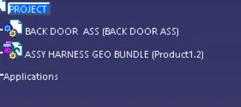
Step: download components and define connectors and clips
1. Download Components:
Begin by obtaining the necessary components for the tailgate wiring harness. Download connectors, clips, and any other relevant parts from reputable sources or specified databases. Ensure that the components align with the project requirements and industry standards.
2. Define Connectors and clips:
Clearly define the specification of the downloaded connectors and clips. This includes parameters such as dimension, pin configuration, and material properties. Document this information for reference during the assembly process.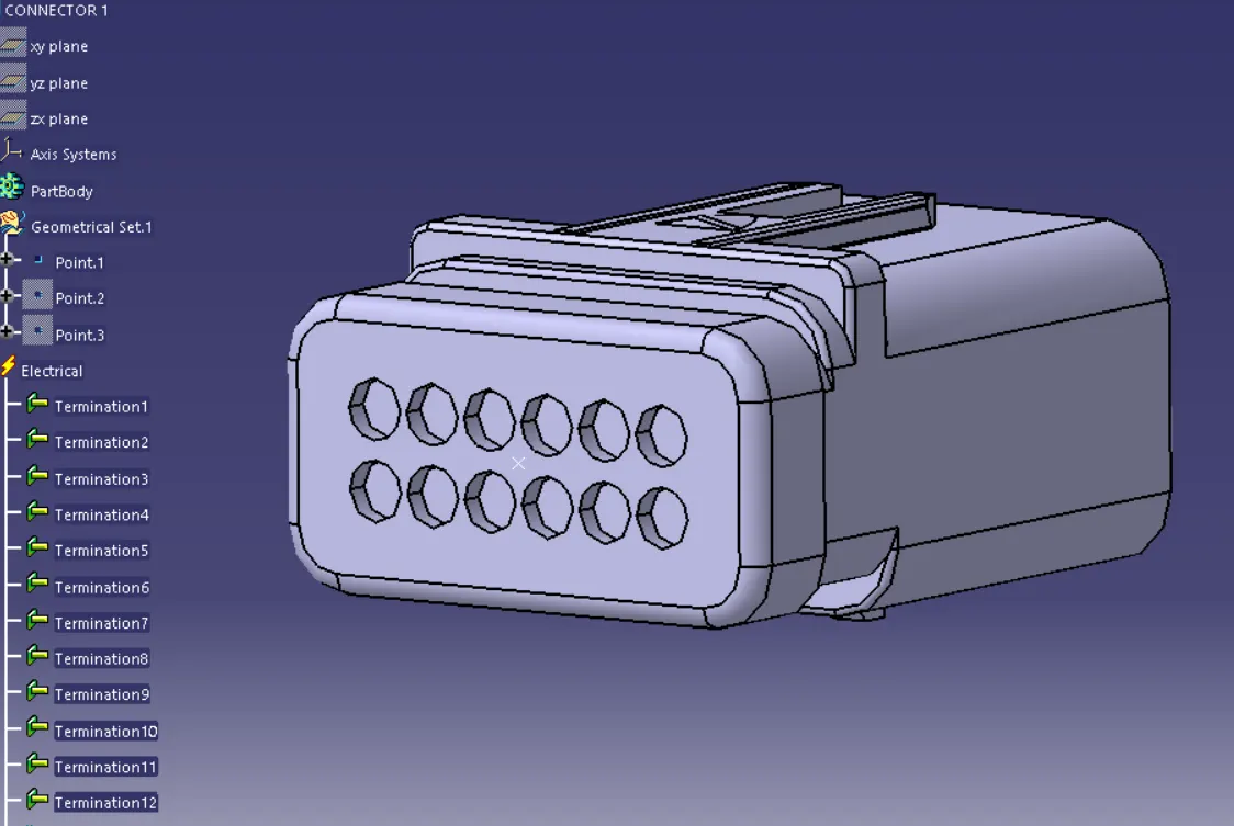
3. Add components to catalogs:
Organize the downloaded components by adding them to catalogs within your design software. Create a systematic categorization to facilitate easy access and integration during the wiring harness assembly. Proper cataloging streamlines the design process and ensures consistency.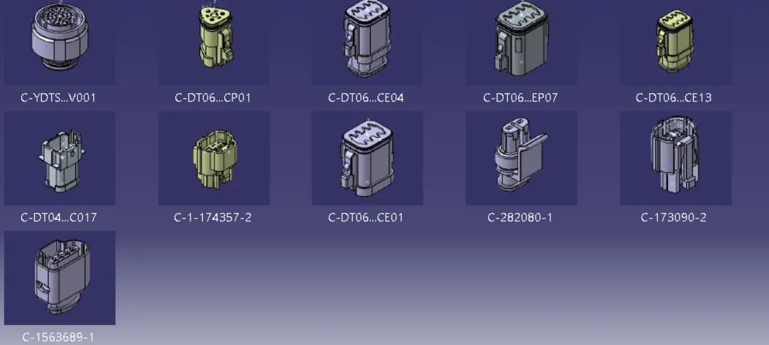
4. Add Components to the Tailgate Wiring Harness File:
Integrate the defined connectors and clips into the tailgate wiring harness file. Use the assembly tools provided by your design software to accurately position and connect these components within the wiring harness. Ensure proper alignment and connection points to meet design specifications.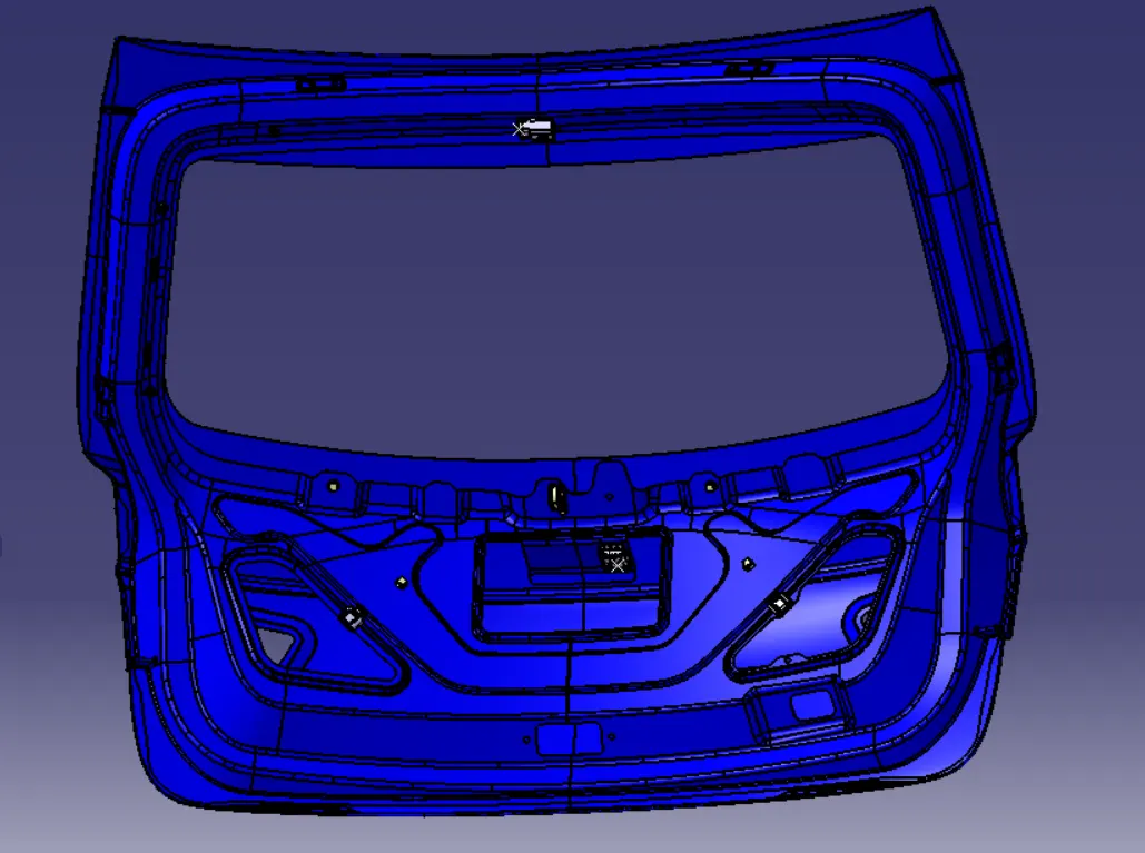
Step: Placing connectors in Required locations for Bundle Connection
1. Identify Connection Points:
Determine the specific locations on the tailgate wiring harness where connectors are required. This includes designated points for the tail lights, license plate lights, rear wiper, and any other components that necessitate electrical connection.
2. Review 3D Model:
Refer to the 3D model of the back door within the context Assembly product file. Identify the optimal positions for placing connectors based on the physical layout of the tailgate and the routing of the wiring harness.
3. Access Catalog Components:
Utilize the previously added connectors from the catalogs created in Step 2. Select connectors that are suitable for each connection point, considering factors such as size, pin configuration, and compatibility with the corresponding components.
4. Place connectors:
using the assembly tools in your design software, place the connectors at their designated locations on the tailgate wiring harness. Ensure precise alignment and connectivity, taking into account the orientation of the connectors and the specific requirements for each connection point.
Arrange the wiring harness to connect with the designated connectors.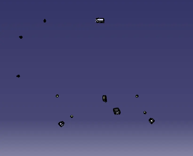
POSITIONING:
To position the connectors, channels, clips, and champs in the given Engine CAD model, follow these steps:
1. Switch to the "Assembly Design" module.
2. Utilize commands such as "Manipulation", "snap", "smart Move", "Translation", or"Rotation" as demonstrated in the provided image. Apply these commands to position the components accurately.
3. Specifically, place the P-Clampps and fir tree cable ties according to the routing specified in the images.
4. Position the interconnect connector on the bracket, ensuring it is correctly placed.
5. similarly, position the guiding channel near the injectors on the cylinder head, aligning it with the specified routing.
By following these steps. you'll ensure that the connectors, channels, clips, and clamps are appropriately positioned in the engine CAD model, adhering to the routing guidelines provided in the images.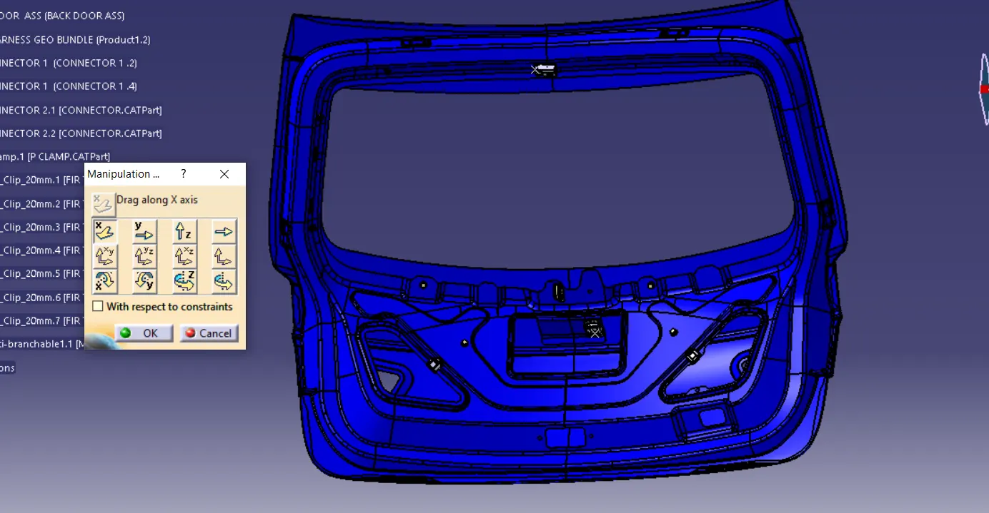
MULTI BRANCHING:
To initiate the creation of a multi-branchable document. follow these steps:
1. Start routing the first bundle segment by clicking on the "Branch Definition" command, as illustrated in the provided image.
2. As you activate the "Branch Definition" command, the module will automatically switch to the Electrical Harness Installation mode.
This process establishes the foundation for a Multi-Branchable document, and by following the specified comment, you can seamlessly transition to the Electrical Harness Installation module for further actions.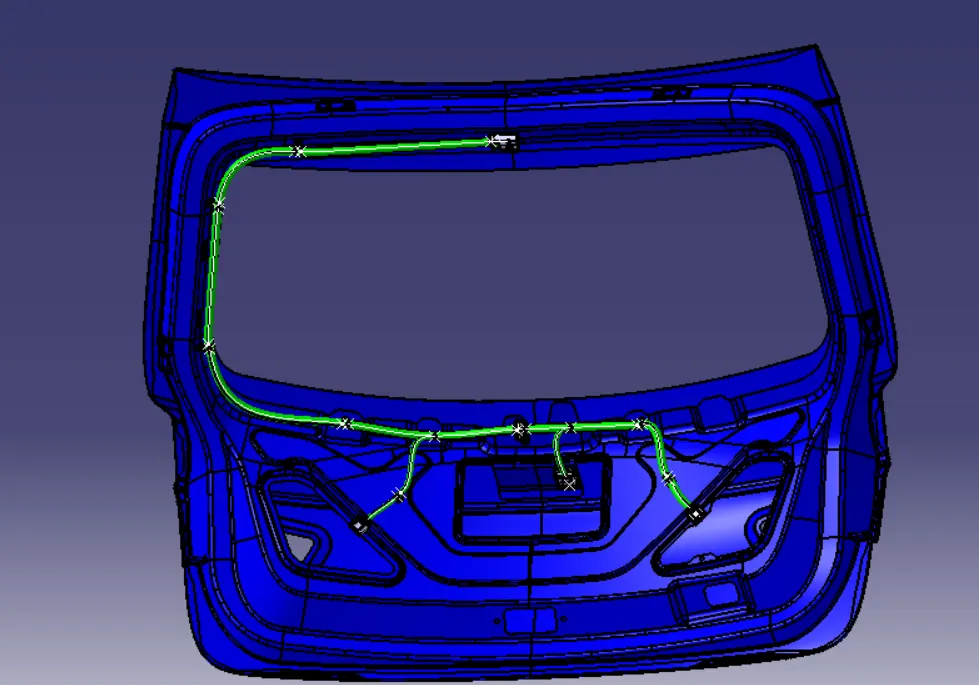
Adding Protective Covering to the Wiring Bundle:
1. To enhance the protection of the wiring bundle, It is necessary to add a protective covering. This covering safeguard the wiring from environmental factors and potential damage.
2. Create a corrugated [COT] tube designed for this purpose and add it to the catalog of available components. Ensure That the specifications and dimensions of the tube are accurately defined.
3. Within The Electrical Harness Assembly workbench, access the"Protective Covering" command.
4. Apply the protective covering to the wiring bundle. following the specific guidelines and configuration as depicted in the accompanying figure. This protective covering ensures the wiring remains shielded from external elements, contributing to the overall durability and reliability of the harness assembly.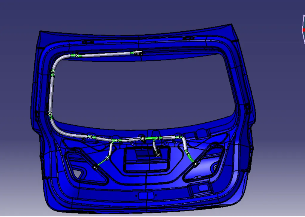
VERIFYING BUNDLE CONTINUITY:
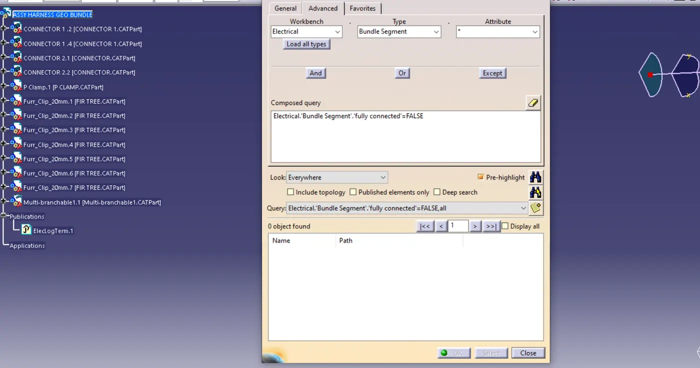
In this step, Begin by ensuring that the multi-branchable options are activated. Then, negative to Edit>search>Advanced>workbench-Electrical>type-Bundle Segment>Attribute-fully connected.
By selecting the "True" option, all connected bundle segments will be displayed, while opting for 'False' will reveal non-connected bundle segments.
For the specific case, we have chosen the ' true' option and initiated the search for results. As a result, all the bundle segments are highlighted, confirming that they are electrically connected, as illustrated in the figure below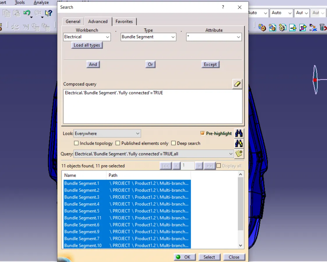
FLATTENING THE WIRING HARNESS:
1. To flatten the wiring harness bundle, initiate by creating a new product file to accommodate the flattened harness configuration.
2. Switch to the electrical harness flattening workbench within the design software.
3. Configure the harness flattening parameters in line with the specifications depicted in the provided figure. These parameters govern the process of achieving the flattened view of the wiring harness.
4. After setting the parameters, proceed by clicking the"Extract" command. This action will enable the software to generate the flattened view of the wiring harness.
5. in the next step, select the engine wiring harness product file to be flattened. This software will utilize the defined parameters to create the flattened representation of the wiring harness within the new product life.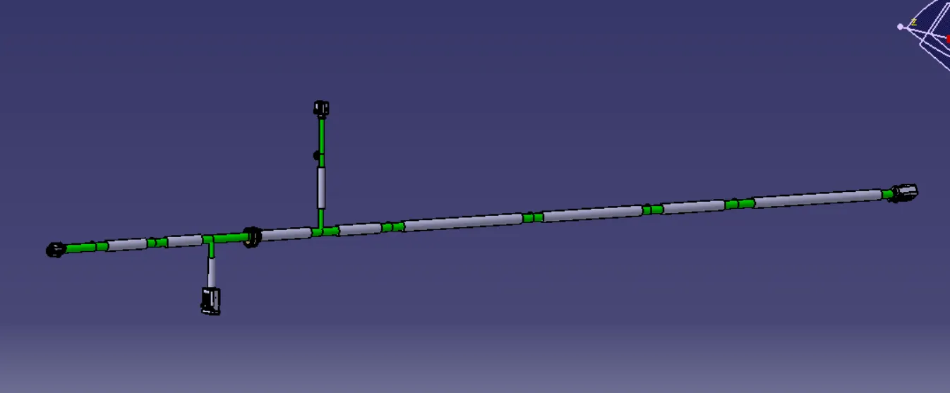
DRAFTING:
To create the "BACKDOOR Wiring Harness Flattening Drawing" follow these steps:
1. open a new CAD drawing file and name it " backdoor wiring harness flattening drawing".
2. Use the"Font view" command to set the view orientation.
3. select the required plane in the flattened harness assembly to pull the flattened view into the drawing sheet.
4. Go to the properties of the drawing.
5. Enable the 3D wireframe option for a clearer representation.
6. Also, enable "3D colors" for a more detailed visualization.
7. click "OK" to apply the changes.
8. Save the drawing file with the desired name.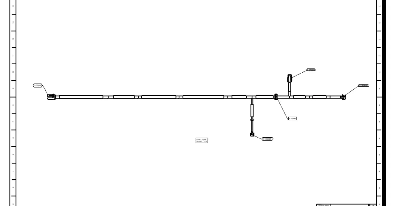
CONCLUSION:
In conclusion, the process of routing the wiring harness on the specified car body in CATIA V5 has been successfully executed, adhering to all relevant packaging rules and industry best practices covered in the course. The design includes the application of protection coverings as required. Utilizing available connector 3D data, or downloaded connectors from www.te.com, contributing to a comprehensive and well-integrated wiring system.
The submission includes essential reports, encompassing clearance analysis, clipping/clamping selection, harness fixing requirements, and harness continuity. Any assumptions made during the design process are also documented. The CATIA 3D data provides a detailed representation of the wiring harness design, ensuring a thorough and well-documented deliverable for further evaluation and implementation.