Project 2
1) Design a Warehouse Building located in Chennai using STAAD Pro Connect Edition. The specification must be as follows:
|
Width |
30m |
|
Length |
50m |
|
Eave Height |
9m |
|
Bay spacing |
6m |
|
Soil type |
Medium |
|
Safe Bearing Capacity |
200 kN/m2 |
|
Roof slope |
1 in 12 |
Assume suitable sections for structural elements. Follow IS800:2007, IS1893 and IS 875
1) Prepare a Design Basis Report for the project :-
PDF formate attach below
2) Create structural model using STAAD Pro Connect Edition :-
3) Prepare DL, LL, WL and EQL load calculations as per IS 875 standards :-
1) Design Foundations using STAAD Foundation :-
4) Design using MS – Excel
a) Steel column :-
Height of column h = 9m
Yeild strength fy = 250N/mm^2
Elastic modulus E = 200000N/mm^2
Material factor γm = 1.1
Step :- 1
Section classification
Properties of selected section
| ISHB | 400 |
| A | 10466mm^2 |
| h | 400mm |
| B | 250mm |
| t | 10.6mm |
| T | 12.7mm |
| rx | 166.1mm |
| ry | 51.6mm |
| Zp | cm^3 |
Flange criterion b/T = 9.84
Web criterion d/t = 35.34
ε = 1
b/T < 10>
d/t < 42>
The section is classified as COMPACT
Step :- 2
Effective length
As both ends pin-jointed
KLx = 9m
KLy = 9m
KLz = 9m
Slenderness ratio
KLx/rx = 54.18
KLy/ry = 174.42
Non-dimensional effective slenderness ratio
λ = 1.964
Step :- 3
To calculate φ
h/bf = 1.60
> 1.2
T = 12.7mm
So, buckling class = b
α = 0.34
φ = 0.5(1+α(λ-0.2)+λ^2)
φ = 2.73
Step :- 4
Claculation of χ
χ = 0.216N/mm^2
Step :- 5
Calculation of fcd
fcd = χfy/γm
= 49.17
Step :- 6
Factored Axial Load
Pd = Afcd
= 514.614kN
b) Rafter :-
Span of I beam = 6m
Dead load = 18kN/m
Imposed load = 40kN/m
Length of bearing = 100mm
Yield strength = 250N/mm^2
Step :- 1
Design load calculation
Factored load = 87kN/m
Factored bending moment = 391.5kNm
Step :- 2
Section modulus required
Zreqd = 1722600mm^3
= 1722.60cm^3
Step :- 3
Section classification
Properties of selected section
| ISMB | 250 |
| A | 475.5mm^2 |
| D | 250mm |
| B | 125mm |
| t | 6.9mm |
| T | 12.5mm |
| Izz | 5131.6cm^4 |
| Iyy | 344.5cm^4 |
| Zp | 459.76cm^3 |
Flange criterion B/2T = 5
Web criterion (D-2T)t = 32.61
ε = 1
B/2T < 9>
(D-2T)/t < 83>
The section is classified as PLASTIC
Step :- 3
Moment of resistance of the cross section
Moment Md = (Zpχfy)/γm
Md = 104.491kNm
< 391>
Hence section ISMB 250 is adequate for flexure
Step :- 4
Shear resistance of the cross section
Shear capacity Vc = 0.6fyAv/γm
Av = 1725mm^2
Vc = 235.23kN
V = 261kN
V/Vc = 1.11
.> 0.6
Step :- 5
Check for web buckling
Slenderness ratio of web = 2.5d/t
d = 225mm
= 70.33mm
Design compressive stress fc = 203N/mm^2
Pw = 315.16kN
> 261
Hence web is safe against shear buckling
Step :- 6
Check for web crippling at support
Root radius of ISMB250 R = 13mm
tf + R = 25.5mm
Dispersion length n^2 = 63.75mm
Pcrip = 245625N
= 245.63kN
< 261>
Hence section adequate for web crippling
Step :- 7
Check for serviceability Deflection
Design load = 58kN/m
Deflection δ = 95.36mm
Allowable deflection = 30mm
Hence serviceability is satisfied
c) Base plate :-
Step :- 1
Strength of concrete fcu = 40 N/mm^2
Yield strength of steel fy = 250 N/mm^2
Material factor γm = .kN
Factored load = 1500 kN
Step :- 2
Steel column section
Thickness of flange T = 12.7 mm
Step :- 3
Area required
Bearing strength of concrete = 0.4fcu
= 16 N/mm^2
Area required = 93750 mm^2
Let size of plate
Bplate = 350 mm
Dplate = 350 mm
Area of plate = 122500 mm^2
Let projection on each side
a = b
= 25 mm
w = 12.24 N/mm^2
Thickness of slab base ts = 7.7 mm
< 12>
So use base plate of size 350mmx350mmx12mm.
d) Pedestal :-
Grade of concrete = 40N/mm^2
Load = 123kN
Moment = 116kNm
Horizontal shear = 13kN
Yield strength = 250N/mm^2
Length of base plate L = 450mm
Width of the base plate B = 350mm
C/C distance of (Ld) of bolt group in Z = 300mm
C/C distance of (Ld) of bolt group in X = 180mm
Bearing strength of concrete fc = 16N/mm^2
Depth of column D = 300mm
Width of column W = 250mm
Step :- 1
Anchor Bolt Details
Dia of anchor bolt = 24mm
No of anchor bolt on each side = 4
Total number of anchor bolt,n = 8
Gross area of the bolt 'Asb' = 452.16mm^2
Net area of the bolt 'Anb' = 352mm^2
Ultimate tensile strength of the bolt fub = 400N/mm^2
Fyb(Anchor bolt) = 240N/mm^2
Step :- 2
Base plate details
Ultimate tensile strength of a plate,fu = 490N/mm^2
Thickness of plate = 16mm
Yield stress of plate = 330N/mm^2
Step :- 3
Anchor bolt design
Area of the plate = 157500mm^2
Stress Max pressure σ1 = F/A+6*Mz/BL^2
= 10.60N/mm^2
< 16>
OK
Min pressure σ2 = F/A-6*Mz/BL^2
= -9.04N/mm^2
< 16>
C = L*σ1/(σ1+σ2)
= 242.89mm
a = L/2-C/3
= 144.04mm
e = (L-Ld)/2
= 75mm
y = (L-C/3-e)
= 294.04mm
Tension in anchor bolts along the length of plate
FT = (Mz-Fxa)/y
= 364.38
Tension per bolt = 91.10kN
shear per bolt,V = 1.63kN
Step :- 4
Shear check
Factored shear force Vsb = 1.63kN
Vd,sd = 81290.9N
= 21.291kN
Factored Vd,sb = 65.03kN
Step :- 5
Tensile check
Factored tensile force in bolt Tb = 91.10kN
Tensile strength of bolt Td,b = Tnb/γmb
Tn,b = 0.9fubAn
= 126720N
= 126.72kN
Tn,b = fybAsb(γmb/γmo)
= 123316N
= 123.316kN
Lesser of two =123.32kN
So, Td,b = 98.65kN
Step :- 6
Combined unity check
(Vsb/Vdb)^2+(Tb/Tdb)^2
Vsb/Vdb = 0.025
Tb/Tdb = 0.92
Unity check = 0.85
< 1>
Hence OK
Step :- 7
Anchor bolt length
Bond strength in tension bd = 1.4N/mm^2
Anchor length required = Tb/(3.14*d*τbd)
= 863.44mm
Let anchor bolt bolt length = 900mm
e) Purlin :-
Step :- 1
Span of the purlin = 7m
Spacing of the purlin = 1.5m
Number of sag rods = 1
Slope of the roof = 5deg
Step :- 2
Dead loads
Weight of sheeting = 5kg/m^2
Self weight of purlin = 4.22kg/m^2
Additional load = 10%
= 0.42kg/m^2
Total dead load = 0.096kN/m^2
Live loads
Live load on roof = 75kg/m^2
= 0.75kN/m^2
Wind loads
Basic wind spped = 50m/s
Terrain category = 2
Building class = B
k1 = 1
k2 = 1
k3 = 1
Design wind speed Vz = 57m/s
Design wind pressure Pz = 1949.40N/m^2
= 1.95kN/m^2
Length of the building I = 50m
Breath of the building w = 30m
Height of the building h = 10.5m
Height of the building at eaves = 9m
h/w = 0.35
I/w = 1.67
External pressure coefficient
Maximum downward Cpe = -0.4
Maximum upward Cpe = -0.7
Internal pressure coefficient
Maximum positive Cpi = 0.5
Maximum negative Cpi = -0.5
For maximum upward wind force
Maximum upward Cpe = -0.7
Cpi = -0.5
Cpe + Cpi = -1.2
Pz = 1.95
Wind pressure for purlin design = -2.339kN/m^2
For maximum upward wind force
Max upward Cpe = -0.4
Cpi = 0.5
Cpe + Cpi = 0.1
Pz = 1.95
Wind pressure for purlin design = 0.195kN/m^2
Step :- 3
Design load calculation
Spacing of purlin = 1.5m
Slope of roof = 5deg
Total dead load = 0.096kN/m^2
DL normal component = 0.144kN/m
DL tangential component = 0.013kN/m
Total live load = 0.75kN/m^2
LL normal component = 1.121kN/m
LL tangential component = 0.098kN/m
WL1 wind load = -2.339kN/m^2
WL normal component = -3.496kN/m
WL2 wind load = 0.195kN/m^2
WL normal component = 0.291kN/m
Summary of loads
| DL+LL | DL+WL1 | DL+LL+WL2 | |
| Normal load | 1.265 | -3.351 | 1.556 |
| Tangential load | 0.111 | 0.013 | 0.111 |
| DL+LL | 0.75(DL+WL1) | 0.75(DL+LL+WL2) | |
| Normal load | 1.265 | -2.514 | 1.167 |
| Tangential load | 0.111 | 0.009 | 0.083 |
Maximum normal component = 1.265kN/m
Step :- 4
Purlin section
Section selected = Zx200x6x2.3
Yield stress of material = 2400kg/cm^2
Flange width b = 60mm
Depth of section d = 200mm
Thickness t = 2.30mm
Length of Lip lip_I = 20mm
Internal bending radius = 3mm
Area = 8.07cm^2
Zxx = 47.72cm^3
Zyy = 10.22cm^3
Ixx = 477.18cm^4
Iyy = 61.34cm^4
Weight of purlin = 6.335kg/m
=4.223kg/m^2
Check for basic properties
t = 2.30mm
w = 49.40mm
Fy = 2400kg/cm^2
w/t = 21.48
< 60>
OK
Check for stress
Span major axis = 7m
Span minor axis = 2m
BM coefficient for Mxx = 10
BM coefficient for Myy = 10
| DL+LL | DL+WL1 | DL+LL+WL2 | |
| Normal load | 6.198 | 16.422 | 7.625 |
| Tangential load | 0.060 | 0.007 | 0.060 |
| Mxx/Zxx | 129.878 | 344.133 | 159.789 |
| Myy/Zyy | 5.895 | 0.672 | 5.895 |
| (Mxx/Zxx)+(Myy/Zyy) | 135.773 | 344.805 | 165.684 |
Maximum compressive stress = 344.80N/mm^2
1435/sq.root of f = 24.44
> 21.48
Hence section OK
Step :- 5
Combined Bending And Shear stresses in web
h/t = 84.96
| DL+LL | DL+WL1 | DL+LL+WL2 | |
| Fbw | 506.539 | 673.697 | 637.697 |
| Fv | 735.223 | 977.847 | 977.847 |
Actual stress
| fbw | 129.878 | 344.133 | 159.789 |
| fv | 5.895 | 0.672 | 5.895 |
| fbw/Fbw | 0.256 | 0.511 | 0.237 |
| fv/Fv | 0.008 | 0.001 | 0.006 |
| Sqrt of sum of squares | 0.257 | 0.511 | 0.237 |
Maximum combined stresses = 0.511
< 1>
OK
Step :- 6
Check for deflection
Number of spans = 3
Deflection = (3/384)(wl^4/EI)
w = 3.351kN/m
Span = 6m
E = 207400N/mm^2
Ixx = 477.18cm^4
δ = 34.29mm
Allowable deflection δ = Span/180
= 33.33mm
> 34.29
Not OK
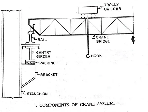
2) Design a simply supported gantry girder to carry electric overhead travelling crane
Step :- 1
Span of gantry girder = 7 m
Span of crane girder = 9 m
Crane capacity = 250 kN
Self-weight of trolley, hook, electric motor etc. = 40 kN
Self-weight of crane girder excluding trolley = 100 kN
Minimum hook approach = 1.0 m
Distance between wheels = 3 m
Self-weight of rails = 0.2 kN/m
Step :- 2
Maximum moment due to vertical load
Weight of trolley + weight of load lifted = 290kN
Self weight of crane girder = 100kN
For maximum reaction on girder, the moving load should be as close to the gantry as possible
Reaction at A RA = 501kN
Reaction at B RB = 281.875kN
Load on gantry girder from each wheel = 251kN
Factored wheel load = 375.833kN
Maximum moment ME = 634.21kNm
Letr self weight of girder = 2kN/m
Dead load = 2.2kN/m
Factored DL = 3.3kN/m
M due to DL = 20.21kNm
M due to impact load = 158.55kNm
Factored moment due to all vertical loads
M = 812.99kNm
Step :- 3
Maximum moment due to lateral load
Horizontal force transferred to rails = 29kN
Horizontal force on each wheel = 7.25kN
Factored horizontal force = 10.875kN
Maximum moment = 18.35kNm
Vertical shear due to wheel loads = 563.75kN
Impact = 140.94kN
Self weight = 9.90kN
Total shear = 714.59kN
Lateral shear due to surge = 20.68kN
Step :- 4
Preliminary section determination
, ,, Minimum economic depth D = L/12
= 583.333mm
Width of compression flange b = L/40 to L/30
= 175 to 233
Required plastic modulus Zp = 1.4M/fy
= 4552721
= 4552.72x10^3
Let us try ISMB600 with ISMC400 on compression flange.
Step :- 5
Properties of selected section
| ISMB | [email protected]/m |
| A | 15600mm^2 |
| h | 600mm |
| b | 210mm |
| tf | 20.3mm |
| tw | 12mm |
| Izz | 91800x10^4mm^4 |
| Iyy | 2650x10^4mm^4 |
| R | 20mm |
| ISMC | [email protected]/m |
| A | 6380mm^2 |
| h | 400mm |
| b | 100mm |
| tf | 15.3mm |
| tw | 8.8mm |
| Izz | 15200x10^4mm^4 |
| Iyy | 508x10^4mm^4 |
| Cyy | 2.42mm |
Step :- 6
Let the distance of N>A> from, t,he tensio,n range by y'
y' = 388.93mm
Izz = 1348.13x10^6mm^4
Zez = 3466240mm^3
For compression flange about y-y axis
I = 16766.7x10^4mm^4
Zey = 838333mm^3
Total area of section = 21980mm^2
Let plastic N>A> be at a distance
Yp = 580.88mm
Zpz = 4410317mm^3
For top flange Zpy = 1078488mm^3
Step :- 7
Section classfication
For ISMB b/t = 4.90
< 9>
d/t = 43.28
< 84>
For ISMC b/t = 5.96
< 9>
Hence section is plastic
Step :- 8
Check for local moment capacity
Local moment capacity for bending in vertical plane
Mdz = fyZp/1.1
= 1002.34kNm
Mdz = 1.2Zefy/1.1
= 945.34kNm
For top flange
Mdy = 245.11kNm
Mdy = 228.64kNm
In the above which ever the minimum value is taken
Mdz = 945.34kNm
Mdy = 228.64kNm
Step :- 9
Check for combined local capacity
(812.99/945.34)+(18.35/228.64)<1>
0.947<1>
Step :- 10
Check for buckling resistance
Md = βbZpfbd
βb = 1
Lt = 7000mm
E = 200000N/mm^2
hf = 597.5mm
Iy = 17850x10^4mm^4
A = 21980mm^2
ry = 90.12mm
fcr,b = 417.43N/mm^2
λ = 0.744
φ = 0.95
= 0.97N/mm^2
fbd = 166.591
Mdz = 734.72kNm
Mdy = 202.84kNm
Hence 1.20>1
Hence section is unsafe against torsional buckling
Step :- 11
Check for shear
Vz = 714.59kN
Shear capacity = Avfyw/(3^0.5x1.1)
= 944755N
= 944.755kN
> 714.59
Now = 566.853kN
Low shear
Step :- 12
Check for web buckling
b = 175mm
n1 = 232.6mm
d = 519.4mm
t = 12mm
= 104.746
Fcd = 128.6N/mm^2
Buckling resistance = 629008kN
> 714.59kN
Step :- 13
Check for deflection at working load
Vertical deflection
Serviceability vertical wheel load = 251kN
Deflection at mid span a = 2000mm
Izz = 1348.13x10^5mm^4
δ = 25.32mm
Horizontal deflection
I = 16766.65x10^4mm^4
δ = 4.88mm
L/750 = 9.33mm
Unsafe in vertical direction.
Safe in lateral direction.
2. Design a simply supported gantry girder to carry electric overhead travelling crane
Given:
Span of gantry girder = 7 m
Span of crane girder = 9 m
Crane capacity = 250 kN
Self-weight of trolley, hook, electric motor etc. = 40 kN
Self-weight of crane girder excluding trolley = 100 kN
Minimum hook approach = 1.0 m
Distance between wheels = 3 m
Self-weight of rails = 0.2 kN/m
Solution:
Maximum moment due to vertical load
weight of trollley + crane capacity = 40 + 250 = 290 kN
Self-weight of crane girder excluding trolley = 100 kN
For maximum reaction on gantry girder, the moving load should be as close the gantry girder as possible.
Ra=
This load is transferred to gantry girder, through two wheels, the wheel base being 3m.
So load on gantry girder from each wheel = 307.77/2 = 158.88 KN
Factored load = 158.88 x 1.5 =230.83 KN
Maximum moments due to moving loads occur under a wheel when the c.g of wheel load &
The wheel are equidistant from the ccentre of girder, as shown below.
RD= 230.83 x (3-1.5-0.75) + 230.83 x (3+0.75) = 148.40 KN
7
Max. moment, Me = 148.40 x 2.25 = 333.90 KN-m
Moment due to impact = 0.25 x 333.90 = 83.47 KN-m
Assume self weight of girder = 2KN-m
Dead load due to self weight + rails = 2+0.2= 2.2 KN-m
Factored DL = 2.2 x 1.5 = 3.3 KN-m
Moment due to DL = = 20.21 KN-m
Factored moment due to all vertical loads,
Mz = 333.90 + 83.47 + 20.21 = 437.58 KN-m
Maximum moment due to Lateral force:
Horizontal force transferred to rails = 10% of weight of trolley plus load lifted = (10/100) x (250+40) = 29 KN
This is distributed over 4 wheels.
So, horizontal force on each wheel = 29/4 = 7.25 KN
Factored horizontal force on each wheel = 1.5 x 7.25 = 10.875 KN
For maximum moment in gantry girder the position of loads is same as earlier except that it is horizontal, hence byproportioning we get.
My = (10.875/230.83) x 333.90 = 15.73 KN-m.
Shear force:
For maximum shear force on the girder, the trailing wheel should be just on the girder as shown below.
Vertical shear due to wheel loads = 230.83 + (230.83 x 3) / 7 = 329.75 KN
Priliminary Section:
Minimum economic depth, L/12 = 7000/12 = 583.33 mm
Width of the compression flange may be taken as (1/40) to (1/30) of span
So, flange width can be taken, L/40 = 7000/40 = 175 mm to L/30 = 7000/30 = 233.33 mm.
Required, Zp = 1.4 x M/fy =
Let us try a ISMB 550 with ISMC 250 on compression flange.