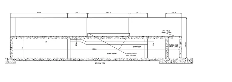
Creating Kitchen layout, Hatching of Architectural elements and sectional view of an Industrial Building in AutoCad
1.Kitchen Layout:
Aim:
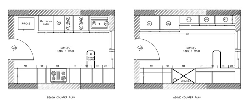
To draw the layout and details of kitchen as shown in the figure. After sketching, need to provide the dimensions and text with the use of layers.
All dimensions are in mm.
PROCEDURE:
- Comments used: Line , Offset , Qleader , dimension , layers
- Intially draw the plan .
- After drawing the plan , project the drawing for creatings views of the kitchen
- Create multiple views such as sectional above and below counter views .
- Hence using the dimension and qleader tool , finish the sketch with required drawings.
Hatching of objects
- Click Home tab-Draw panel-Hatch.
- On the Properties panel Hatch Type list, select the type of hatch that you want to use.
- On the Pattern panel, click a hatch pattern or fill.
- On the Boundaries panel, specify the how the pattern boundary is selected:
- Pick Points. Inserts the hatch or fill within a closed area that is bounded by one or more objects.
- Select Boundary Objects. Inserts the hatch or fill within a closed object.
- The selection method is retained until you change it.
- Click an area or object to be hatched.
- On the ribbon, make any adjustments as needed:
- On the Properties panel, you can change the hatch type and colors or modify the transparency level, angle, or scale for the hatch.
- On the expanded Options panel, you can change the draw order to specify whether the hatch and its boundary are displayed in front of or behind other objects.
- Press Enter to apply the hatch and exit the command.
- Hatch the brick wall with hatch type as ANS132 and hatch other part as solid and grey colour.
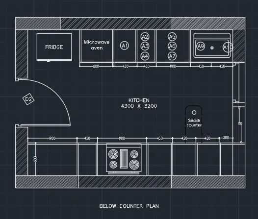
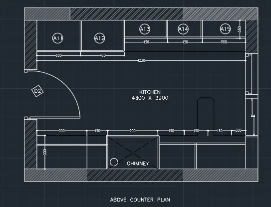
Result:
2. Elevation of Building:
AIM:
TO CREATE ELEVATION AND HATCHING THE STRCTURAL AND NON-STRUCTURAL ELEMENTS OF THE BUILDING LIKE WALLS, COLUMNS ETC.
Procedure:
- Comments used: Line , Offset , Qleader , dimension , layers , Hatch , Trim , Extent , Polyline , etc..
- Intially draw the plan .
- After drawing the plan , project the drawing for creatings views of the elevation
- Create multiple views such as elevation
-
Hatching of objects
- Click Home tab-Draw panel-Hatch.
- On the Properties panel Hatch Type list, select the type of hatch that you want to use.
- On the Pattern panel, click a hatch pattern or fill.
- On the Boundaries panel, specify the how the pattern boundary is selected:
- Pick Points. Inserts the hatch or fill within a closed area that is bounded by one or more objects.
- Select Boundary Objects. Inserts the hatch or fill within a closed object.
- The selection method is retained until you change it.
- Click an area or object to be hatched.
- On the ribbon, make any adjustments as needed:
- On the Properties panel. you can change the hatch type and colors or modify the transparency level, angle, or scale for the hatch.
- On the expanded Options panel. you can change the draw order to specify whether the hatch and its boundary are displayed in front behind other objects.
- Press Enter to apply the hatch and exit the command.
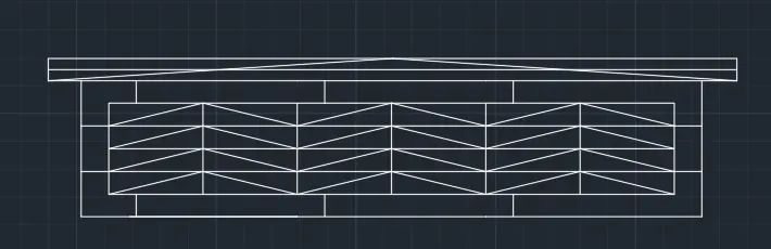
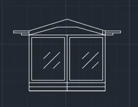
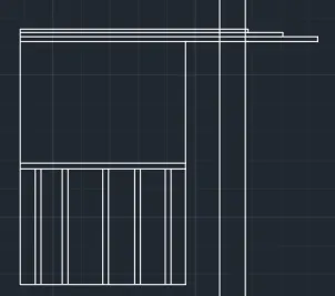
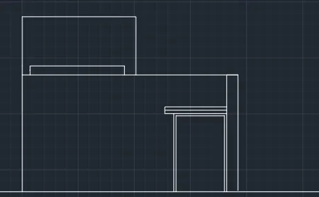
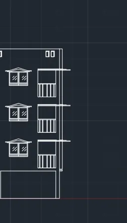
Result: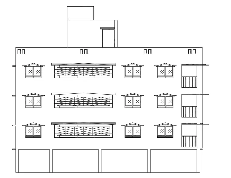
3.
AIM:
To create the section view of an industrial building.
Procedure:
Commands used:
- Limits command
- X-Line command
- Line command
- Offset command
- Hatch command
- Dimlinear command
- Dimstyle command
- Units command
- Extend command
- Fillet command
- Trim command
- Join command
- Line weight command
- Line type command
- Object snap command
- Rectangle command
- Zoom command
RESULT: