Project 2
Aim :-
Conduct the post-processing of the results once the analysis is complete. The first task includes checking the base pressure and settlement beneath the base slab which should be within the limits mentioned in Project-1. If these limits are exceeded then the dimensions need to be increased or decreased so that the base pressure and settlement are under control.
Once the foundation is checked, report the following results in order to carry out the structural design of elements.
- Design Maximum and Minimum Moments in walls and base slabs (Wood Armer Simplified Method)
- Design Maximum and Minimum Shear Stresses in walls and base slabs
- Design Maximum and Minimum Axial Stresses in walls and base slabs
Once the post-processing of results is done, carry out the structural design of the elements by conducting the following checks
- Construct an excel spreadsheet for calculating the reinforcement requirement in short and long walls and base slabs. For calculating the required design reinforcement, the contribution due to direct tension also needs to be added if significant and it can be calculated by adopting the following method (discussed in Week-3):
M,net = M – T . x
Ast1 = (0.5 fck / fy) {1-√[1-(4.6 B.M./(fck.b.d²))]}
Ast2 = T / 0.87 fy
Total Ast, req = Ast1 + Ast2
M = Design moment obtained from Wood Armer equations
T = Design Tension force in the section (Stress x c/s area of FE element)
x = distance of tension reinforcement from the center line of the section
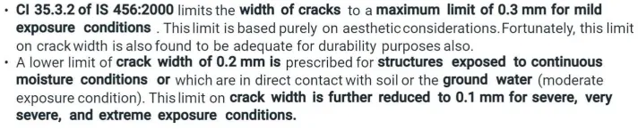
- Check crack widths of short and long walls and base slab and ensure that it is less than 0.2mm.
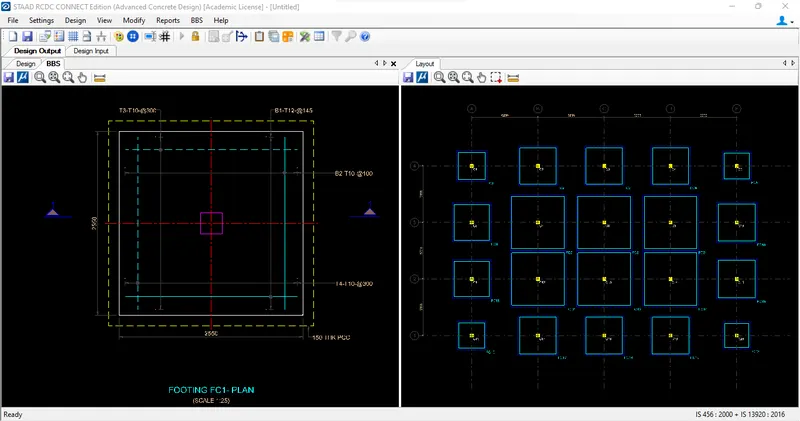
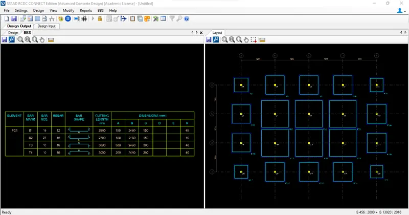
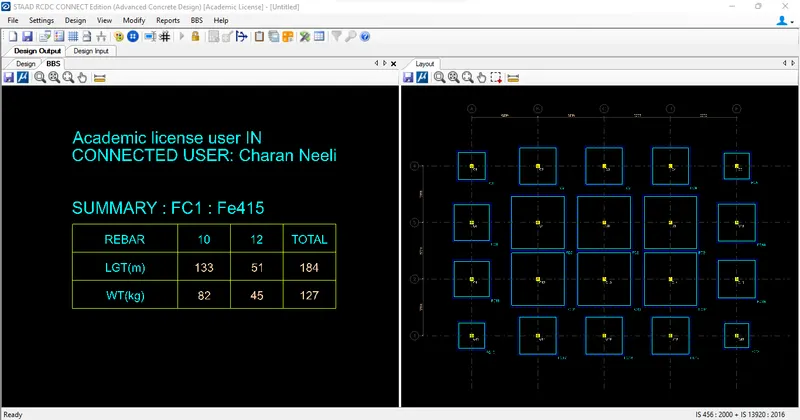
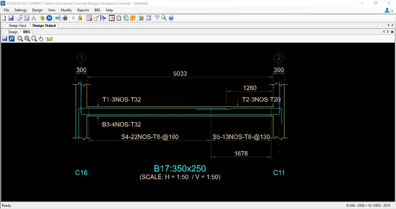
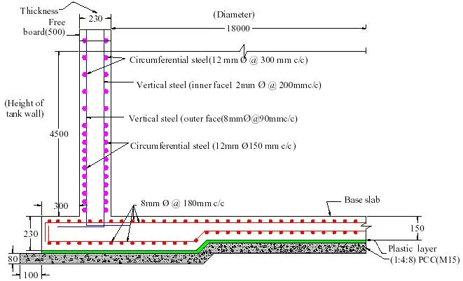
- Draft cross-sectional reinforcement detail (plan and elevation) using a CAD software. If CAD is not available, sketch the details using any drawing tool and clearly indicate all the details.
Procedure :-
Materials unit weight as per the code
Safe Bearing Capacity = 18kN/m^3
Plain cement concrete = 24kN/m^3
Reinforced cement concrete = 25kN/m^3
Cement concrete screed = 20kN/m^3
Cement masonry = 22kN/m63
Structural steel = 78.5kN/m^3
Loads of a building
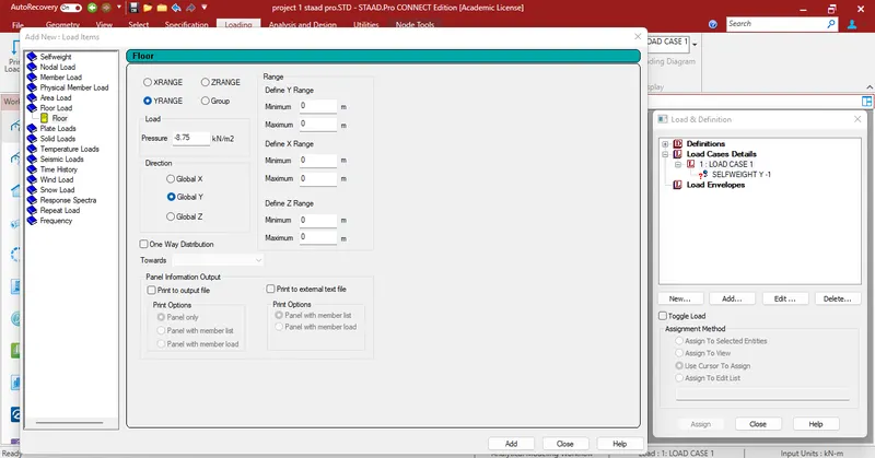
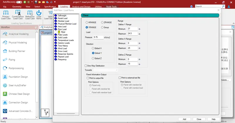
Slab weight = 3.75kN/m^2(0.15mx25kN/m^3)
Partitions = 1.5kN/m^2
Floor finish = 2.5kN/m^2
, Others = 1kN/m^2
Total floor load = 8.75kN/m^2
Slab unit weights
Slab weight = 3.75kN/m^2(0.15mx25kN/m^3)
Insulations and water proofing = 0.5kN/m^2
MEP services = 0.5kN/m^2
Others = 0.5kN/m^2
Total roof load = 5.25kN/m^2
Common corridor = 3kN/m^2
Total floor load =3kN/m^2
Accessible roof = 1.5kN/m^2
Total roof load = 1.5kN/m^2
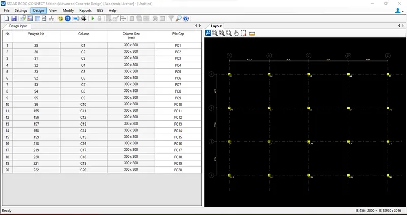
Design of slab(IS-456)
Span shorter direction(clear) Ly = 3.125m
Span longer direction(clear) Lx = 5.5m
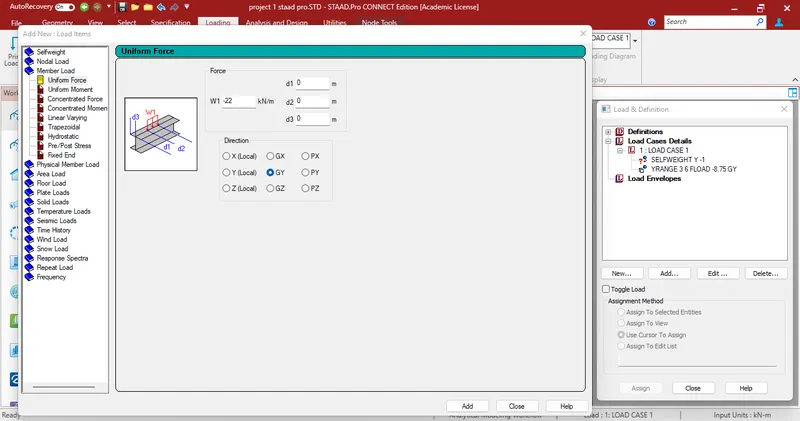
Live load on the slab(LL) = 3kN/m
Compressive strength of concrete(Fck) = 25N/mm^2
Yield strength of steel(Fy) = 415N/mm^2
Unit weight of concrete(Yc) = 25kN/m^3
Unit weight of floor finish 100mm(Y) = 22kN/m^3
Clear concrete cover = 25mm
Bearing slab(B) =250mm
Step - 1
Span to effective depth ratio L/d = 32
Minimum effective depth(d) = 97.67mm
Overall depth(D) = 127.66mm
Dia of bars in shorter direction = 10mm
Dia of bars in longer direction = 10mm
Effective depth(d) = 120mm
Loading on the slab
Dead load of the slab(DL) = 3.75kN/m^2
Super dead load = 5kN/m^2
Live load on the slab = 3kN/m^2
Total load on the slan = 11.75kN/m^2
Design load = Total load x load factor
= 17.63kN/m^2
Effective span Lx = 3.25m
Ly = 5.62m
Lx/Ly = 1.732 (two way)
| 1.5 | Alpha x | 1.75 | Alpha y | |
| For negative moments (at top) | 0.075 | 0.104683 | 0.107 | 0.084 |
| For positive moments (at bottom) | 0.056 | 0.103307 | 0.107 | 0.063 |
Step - 2
BM per unit width of slab
| Mx=αxwLx^2 | My=αywLy^2 | |
| For negative moments (at top) | 19.43 | 15.59kN-m/m |
| For positive moments (at bottom) | 19.17 | 11.69kN-m/m |
Shear force V = 0.5WLx =28.6 kN/m
Step - 3
To check the effective depth of slab
Mu,lim = 0.138Fckbd^2
d = 74.55mm
Step - 4
Depth of slab for shear force
Tc,max = 3.1N/mm^2
Tc = 0.3
K = 1.2
D = 200mm
Tc = 0.3N/mm^2
Tv = Vu/bd
= 0.24N/mm^2
Tv<Tc<Tc,nax
0.24<0.36<3.1
SAFE
Step - 5
Determination of area of steel
Mu = 0.87FyAstd(1-AstFy/Fckbd)
For negative moment
Mutop = 19.43kN/m
Ast = 561.65mm^2/m
For positive moment
Mubottom = 19.17kN/m
Ast = 554.27mm^2/m
Determination of distribution steel
Astmin = 0.12bd
= 114mm^2
Selection of steel reinforcing bars
Area of bars(Top steel) = 78.5mm^2
Spacing = 140mm
= 125mm
provide 16mm bqars at a spacing 125mm
Area of bars(Bottom steel) = 78.5mm^2
Spacing = 142mm
=125mm
Provide 16mm bars at a spacing 125mm
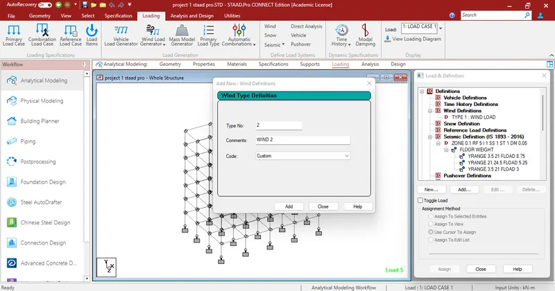
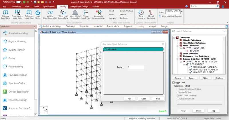
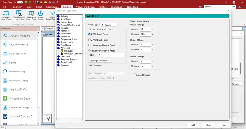
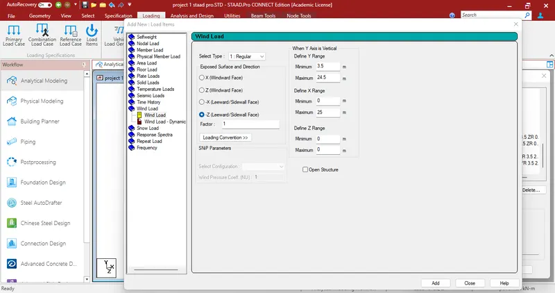
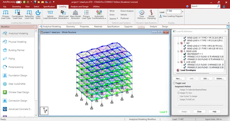
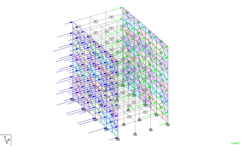
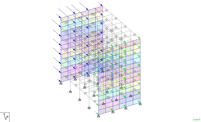
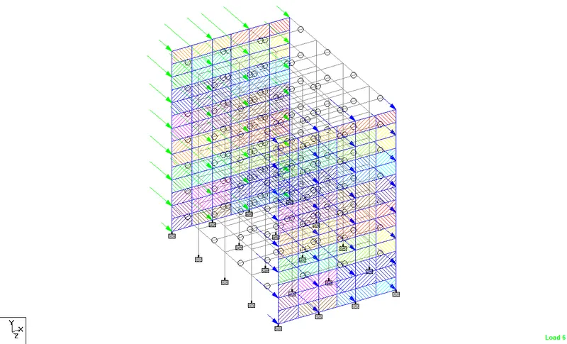
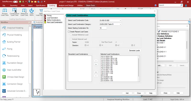
Calculation of wind load (IS875-Part 3)
Design wind speed Vz = Vbk1k2k3k4 m/s
Basic wind speed(Bengalore) Vb = 33m/s
Probability factor k1 = 1
Terrain factor k2 = Category 4B
Topography factor k3 = 1
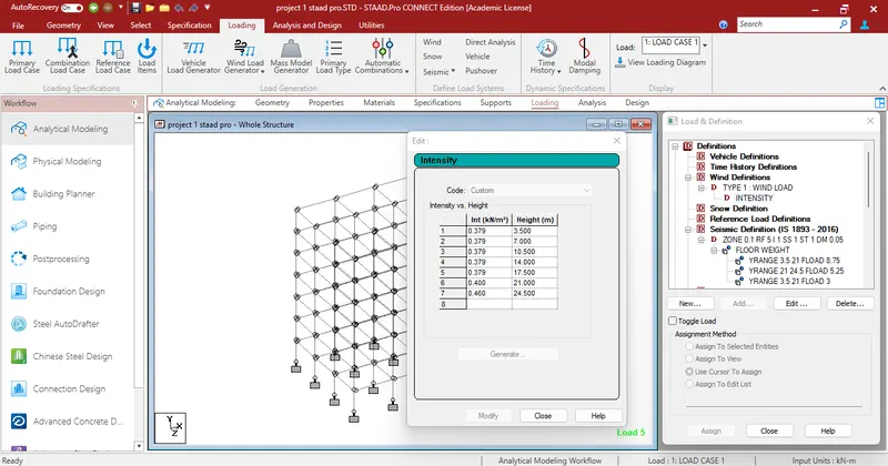
Design wind pressure Pz = 0.6Vz^2
| Floor | Height | k2 | Vz | Pz | Pz in kN |
| 1 | 3.5 | 0.76 | 25 | 377.40 | 0.38 |
| 2 | 7 | 0.76 | 25 | 377.40 | 0.38 |
| 3 | 10.5 | 0.76 | 25 | 377.40 | 0.38 |
| 4 | 14 | 0.76 | 25 | 377.40 | 0.38 |
| 5 | 17.5 | 0.76 | 25 | 377.40 | 0.38 |
| 6 | 21 | 0.76 | 26 | 397.53 | 0.40 |
| R | 24.5 | 0.76 | 26 | 461.04 | 0.46 |
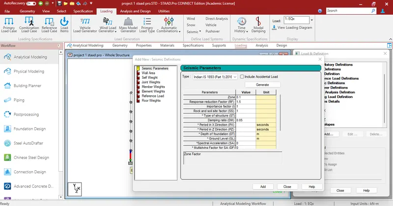
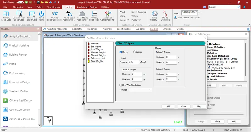
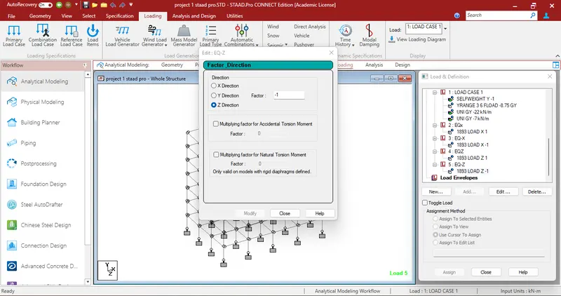
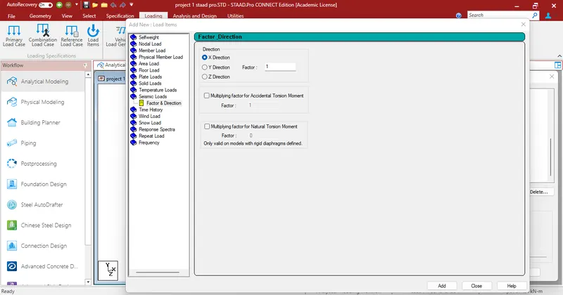
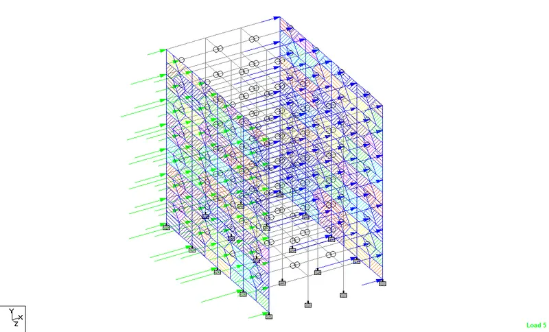
Calculation of Seismic Load (IS1893-Part I)
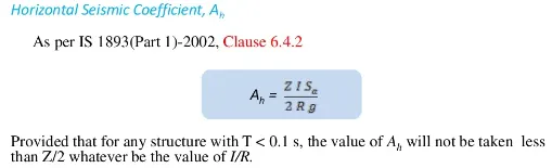
Design base shear VB = Ah x W
Where,
Ah = horizontal seismic coefficient as calculated as per 6.4.2
W = Total weight of the structure
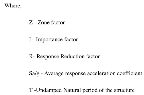
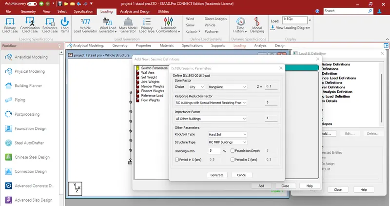
Zone factor Z = 0.1 (Bngalore)
Soil condition factor Sa/g
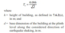
Height of building h = 24.5m
Base dimension of building
Along-X = 25m
Along-Z = 16m
T along-X = 0.5513sec
T along-Z = 0.4410sec
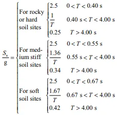
Sa/g for hard soil = 1/T = 1.814 Along X
= 2.268 Along Z
Responce reduction factor R = 3
Importance factor I = 1.2
Horizontal accelaration co-efficient Ah = 0.0363
= 3.6812%
Seismic weight
Area of each floor A = 400m2
Due to dead loads Typical floor DL = 12.5kN/m2
W DL = 5000kN
Due to dead loads, roof
DL roof = 9kN/m2
W DL roof = 3600kN
Due to live loads, Typical floor LL = 3kN/m2
W LL = 300kN/m2
Due to live loads, Roof LL = 1.5kN/m2
W LL roof = 0
Total seismic weight W = 35400kN
Design base shear VB = AhxW
= 1605.44kN
 ,
,
The rules to satisfy the limit state of cracking in slabs :-
Minimum and maximum flexural reinforcement specified in code for beams or slab elements :-
The minimum reinforcement ratio is the lowest possible quantity of steel that should be embedded in structural concrete elements to prevent premature failure after losing the tensile strength. The minimum reinforcement ratio controls the cracking of concrete members.
The maximum reinforcement ratio is the largest steel area that can be put into concrete members like columns and beam. In a reinforced concrete beam, the provision of extra reinforcement above the maximum reinforcement ratio would not be beneficial since the concrete would get crushed before the full strength of steel is used.
The collapse of a concrete structure is sudden and does not show any signs before failure. The maximum reinforcement ratio ensures concrete members' economy and provides safety against brittle failure of concrete.
Finally, the required reinforcement area of the designed concrete member should not exceed the maximum reinforcement ratio and should be less than the minimum reinforcement ratio. Therefore, the designed member should be checked for this requirement.
Minimum Reinforcement Ratio
The purpose of the minimum reinforcement ratio is to control cracking and prevent sudden failure by equipping the member with adequate ductility after the loss of concrete's tensile strength due to cracking.
Building construction codes such as ACI 318-19, provides minimum reinforcement ratio for different reinforcement concrete members such as beams and columns.
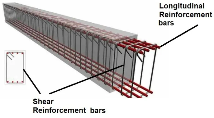
1. Minimum Reinforcement Ratio in Beams
In reinforced concrete beams, if the cracked section's flexural strength is lower than the moment that produced cracking of the previously uncracked section, then the beam would fail upon the formation of the first flexural crack, without showing any distress.
The minimum reinforcement ratio, which can be computed using the equation provided by ACI 318-19, can prevent a concrete beam's premature failure. The minimum reinforcement for beams can be computed using the following expression:

Where:
As,min: minimum area of steel, mm2
fc': compressive strength of concrete, MPa
fy: steel yield stress, MPa
bw: width of web in T-beam, and width of beam in rectangular beam, mm
d: effective depth measured from extreme concrete compression fiber to the center of steel bars, mm
2. Minimum Reinforcement Ratio in Slabs
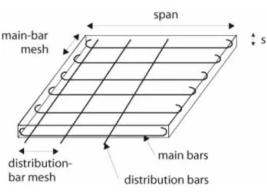
The minimum reinforcement area for slab is the temperature and shrinkage reinforcement installed to control cracks due to shrinkage in concrete and temperature variations. It is not required to provide a reinforcement area more than the temperature and shrinkage reinforcement.
As= ρbd Equation 2
As: shrinkage and temperature reinforcement, mm2
b: width of slab strip considered for design purpose which is 1 m
d: effective depth, mm
3. Minimum Reinforcement Ratio in Uniform Footing
The minimum reinforcement ratio for uniform footing is similar to that of a slab i.e temperature and shrinkage reinforcement ratio.
4. Minimum Reinforcement Ratio in Columns
The minimum reinforcement ratio for columns is required to provide resistance against bending, which may occur irresective of analytical results. It is also needed to decrease the effect of shrinkage and creep of the concrete under sustained compressive stresses.
The minimum reinforcement ratio in the column prevents steel bars from yielding under sustained service load. ACI 318-19 specifies the minimum longitudinal reinforcement ratio for a column as 0.01 times the column's gross area.
5. Minimum Reinforcement for Connections between Cast-in-place Members and Foundation
The minimum reinforcement area that crosses the cast-in-place column or pedestal and foundation interface should be 0.005 times the gross area of the supported member.
Maximum Reinforcement Ratio
The maximum reinforcement ratio is an upper limit of steel quantity that can be put into concrete members. It is commonly provided for various reasons, which are discussed below:
1. Maximum Reinforcement Ratio in Beams
The maximum reinforcement ratio for beams is provided to prevent concrete crushing, which is an undesired mode of failure and prevented by the ACI code. It also avoids the use of excessive steel area that does not offer real benefits. Therefore, it helps to bring economy in the design of concrete beams.
If a beam possesses a higher reinforcement ratio than the maximum reinforcement ratio, it is called an over-reinforced concrete beam and usually fails in compression.
Over-reinforced concrete beam fails in compression before utilizing the full-strength potential of steel bars. The maximum reinforcement ratio for beams can be calculated using Equation 3.

2.Maximum Reinforcement Ratio in Columns
The maximum reinforcement has been established to make sure that the concrete can be compacted adequately around steel bars and to ensure that the designed columns are similar to the test specimens, as per ACI 318.19.
The maximum reinforcement ratio for columns is 0.08 times the gross area of the column. It brings economy to the design of columns and prevent steel congestion, which otherwise hinders proper concrete placement.
Practically, it is recommended to consider a maximum reinforcement ratio of 0.04 times the column's gross area to avoid over-reinforcement at steel bars' splicing locations.
Minimum Reinforcement Ratio for Shear
Similar to minimum flexural reinforcement discussed above, ACI 318-19 sets minimum reinforcement ratio for shear in beams, etc.
1. Minimum Shear Reinforcement Ratio in Beams
A minimum area of shear reinforcement should be provided in all regions of a beam where applied shear is greater than half the designed shear strength of concrete.
The minimum shear reinforcement (Av,min) in beams should be the greater of the following:
Av,min=0.062*fc'(0.5)*(bw*s/fyt) Equation 4
Av,min=0.35*(bw*s/fyt) Equation 5
Where:
s: center-to-center spacing of stirrups, mm
fyt: yield stress of stirrup steel bar, MPa
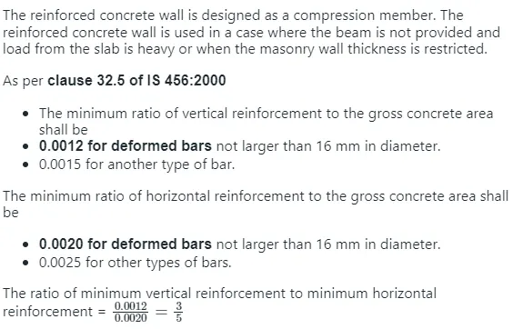
2. Minimum Longitudinal and Transverse Reinforcement in Cast-in-place Walls
If the in-plane applied shear (Vu) of the cast-in-place wall is equal to or less than the value derived from Equation 6, use values provided in Table-1 as a minimum reinforcement for both longitudinal and transverse direction.
However, if the in-plane applied shear (Vu) is greater than the value derived from Equation 6, then (ρt= 0.0025) and the value of (ρℓ) is the greatest of 0.0025 and the result from Equation 7.


Where:
hw: height of entire wall from base to top, mm
lw: length of entire wall, mm
Lean patch of concrete or PCC is used between soil and RCC footing :-
Lean concrete: Its role is to provide the uniform surface to the foundation concrete and to prevent the direct contact of foundation concrete with the soil. Its thickness is 5 cm. It is mixed at 150 kg/m3. Concrete for ground beam, column footings: This is mixed at 350 kg/m3.
In terms of strength, naturally, RCC is stronger because the reinforcement helps in load-carrying capacity. PCC is weaker and is only used for layering surfaces like plastering work or flooring and most importantly in the layering if excavation to cast footings.
Development length for HYSD base in compression.
ld=0.87fyϕ4τbd(1.25×1.6)
=0.87×415×164×1.4×(1.25×1.6)=515.79mm
Result :-
Successfully complete conduct the post processing of the results once the analysis is complete. The first task includes, checking the base pressure and settlement beneath the base slab which should be within the limits mentioned in Project-1. If these limits are exceeded then the dimensions need to be increased or decreased so that the base pressure and settlement is under control.
Once the foundation is checked, report the following results in order to carry out the structural design of elements.
- Design Maximum and Minimum Moments in walls and base slabs (Wood Armer Simplified Method)
- Design Maximum and Minimum Shear Stresses in walls and base slabs
- Design Maximum and Minimum Axial Stresses in walls and base slabs
Once the post processing of results is done, carry out structural design of the elements by conducting the following checks
- Construct an excel spreadsheet for calculating the reinforcement requirement in short and long walls and base slabs. For calculating the required design reinforcement, the contribution due to direct tension also needs to be added if significant and it can be calculated by adopting the following method (discussed in Week-3):
M,net = M – T . x
Ast1 = (0.5 fck / fy) {1-√[1-(4.6 B.M./(fck.b.d²))]}
Ast2 = T / 0.87 fy
Total Ast, req = Ast1 + Ast2
M = Design moment obtained from Wood Armer equations
T = Design Tension force in the section (Stress x c/s area of FE element)
x = distance of tension reinforcement from the center line of the section
- Check crack widths of short and long walls and base slab and ensure that it is less than 0.2mm.
- Draft cross-sectional reinforcement detail (plan and elevation) using a CAD software. If CAD is not available, sketch the details using any drawing tool and clearly indicate all the details.