Project 2
WIRING HARNESS DESIGN_PRJECT-2
OBJECTIVE:
To route the wiring harness on given car body(Tail gate) & prepare flatten view drawing.
INPUT:
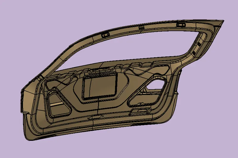
From the the given Engine CAD data thus the required Connectors, Clips & Clapms are listed below and the followings are,
| S.NO | ELECTRICAL & MECHANICAL PARTS | TYPE | PURPOSE | QTY |
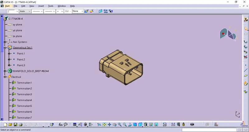
| 01 | C-776438-4 | CONNECTOR | INTER CONNECTION CONNECTOR | 01 |
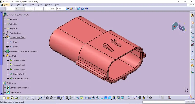
| 02 | C-174359-2 | CONNECTOR | 3-POLE REAR LIGHTING CONNECTOR (LH&RH) | 02 |
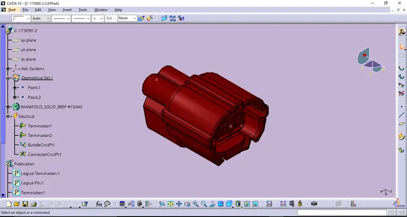
| 03 | C-173090-2 | CONNECTOR | 2-POLE SIGN BOARD LIGHTING CONNECTOR | 02 |
| 04 | FIR-TREE CLIPS | CLIP | MOUNTING EQUIPMENTS | 13 |
| 05 | COUROGATED TUBE | PACKAGING | PROTECTING COVERING | *** |
These are the functional requirements of the given Car body (Tail gate) Wiring Harness Routing Connectors,Clips, Clamps & etc., And abvove CAD data's are getting created/downloaded from www.te.com.
TOOL USED: CATIA V5
PROJECT-1_WIRING HARNESS DESIGN
STEP_1: FUNCTIONAL REQUIREMENTS & DESIGN CONSIDERATIONS OF WIRING HARNESS PACKAGING RULES
- Keep minimum of 200mm of distance between two clamps in a strainght branch.
- Keep minimum of 25 mm of distance between clips and branching points.
- Enough clamps shall be provided to ensure positive clearance with surroundings and safety of wiring harness.
- To provide proper slack at end connectors so that there will be no tension on the wire bundle.
- Avoid sharp edges on the engine parts and if it is not possible then ensure (clearance min - 10mm) to provide protection coverings to prevent damage of the wire bundle.
- Ensure that protection covering end extrimity clearance to the connector min 30 mm.
- Convert sharp edges to smooth surfaces by applying rubber beddings on itself to protects bundle damage.
STEP_2: ELECTRICAL PART WORKBENCH
In this Electrical Part Design Workbench thus the given Mechanical part bodies of the connectors will get converted into Electrical Part by defining its appropriate Electrical definitions and its Electrical properties. And here by following below as,
1_ Create/Download the CAD data for the required Part 3D.
2_ Create required Geometrical properties by using Part Design Workbench.
3_ Define Electrically like Define as Connector, Back shell, Supporting, & Mounting Equipment, etc.
4_ Define its required Electrical properties like Define as Connector connection point, Bundle connection point, Cavity connection point & etc., after that add the entire cad data in to the catalogue browser itself with electrically defined.
And here thus the given Connectors are become electrically defined by applying the above all and the followings are,
CONNECTOR_C-776438-4
CONNECTOR_C-174359-2
CONNECTOR_C-173090-2
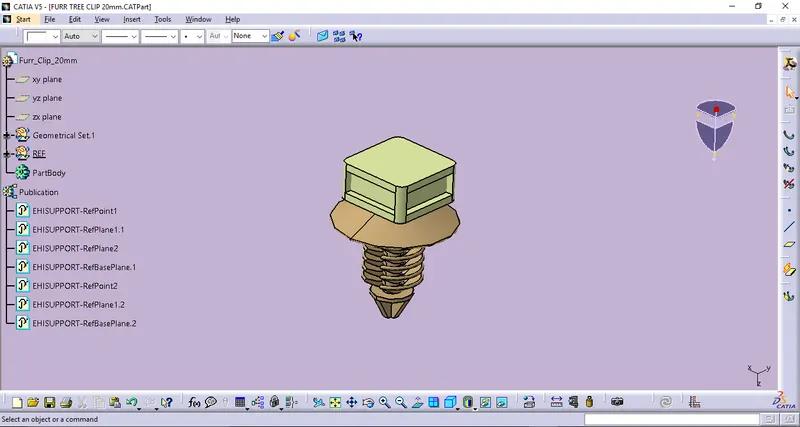
CLIP_FIR-TREE CLIP
STEP_3: ASSEMBLY WORKBENCH
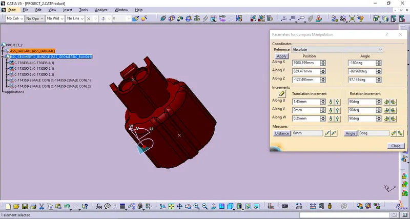
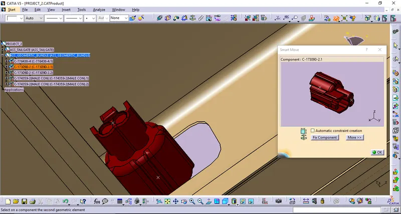
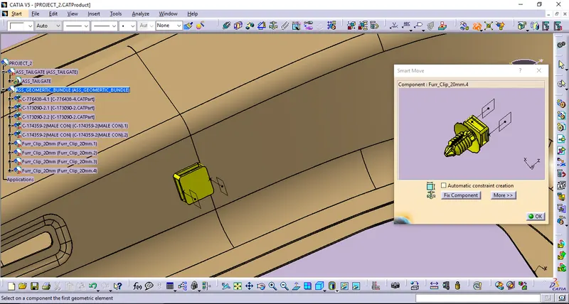
In this Assembly Workbench (Mechanical) has to be widely used to allocate the electrically defined parts in the proper positions based on the layout. And here few commands are used to locate the electrical parts by using Move toolbar commands like Manipulation, Snap, Smart move and by using the Translation/Rotation by using Compass. In before start positioning ensure that all the Electrical parts add into the Product file and keep following measurements in the given layout, here I create a layout Sketches by using the Part workbench in the appropriate dimensions which will helps us easier to locate.
BY using compass defining to locating the following connectors.
By defining smart move.
STEP_4: ELECTRICAL HARNESS ASSEMBLY WORKBENCH
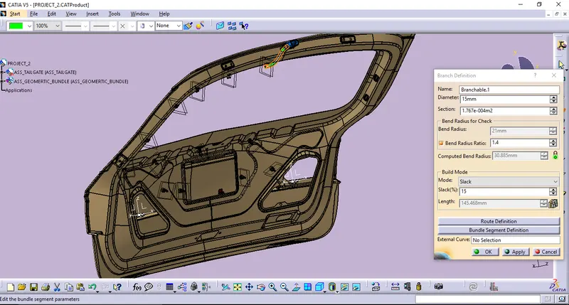
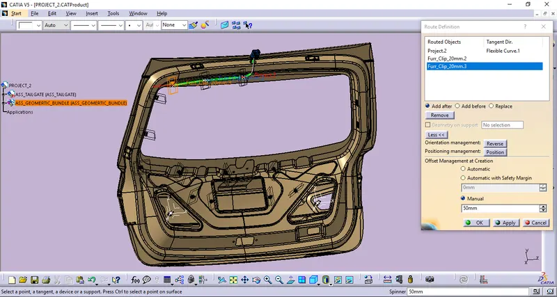
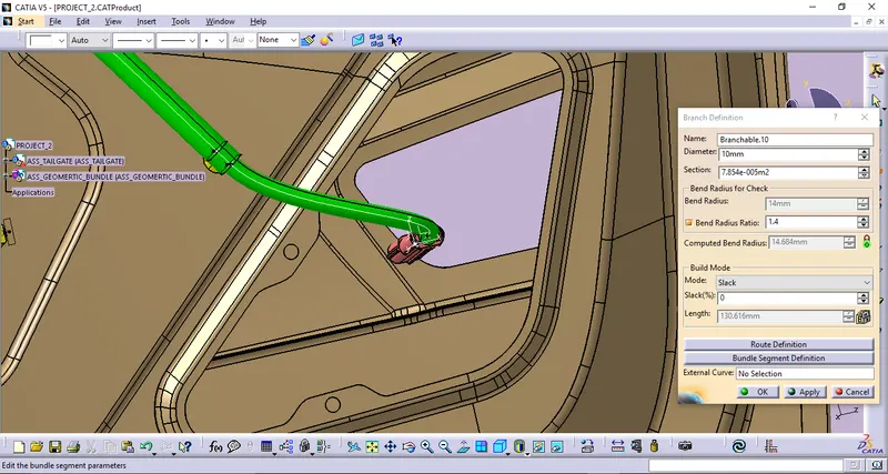
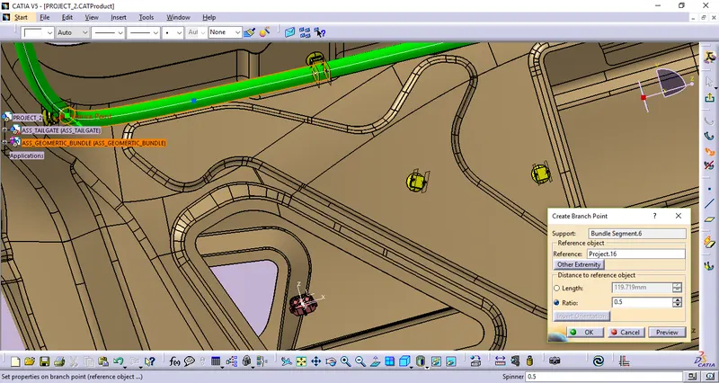
In this Electrical harness assembly workbench which will used creating harness routings by defining the Mechanical product file becomes converted as Electrical Harness by clicking Geometrical bundle. Then by using multi branchable command start routing the harness assembly design. And the followings are,
By defining branch definition.
By defining routing definition.
By defining branch definition.
By defining create branch point.
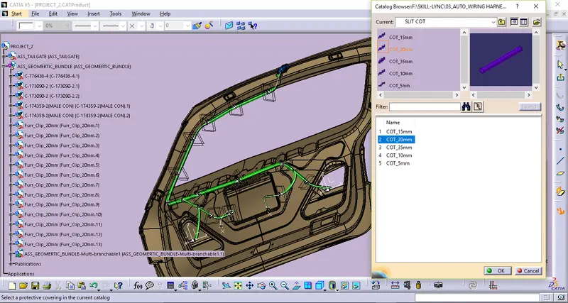
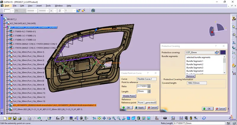
APPLYING PROTECTIVE COVERING
BUNDLE CONTINUITY CHECK
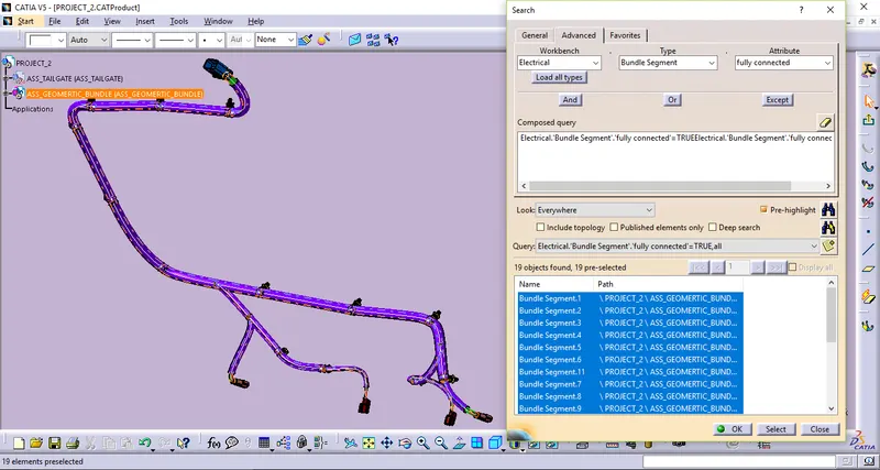
In this step, first we have to make sure that multi-branchable is selected then we have to go in Edit>Search>Advanced>Workbench-Electrical>Type-Bundle Segment>Attribute-Fully Connected
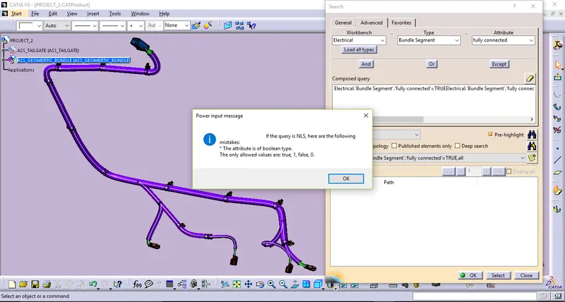
- By selecting 'True' option will show all the connected bundle segments while selecting 'False' option will show all the non-connected bundle segments.
- Here, we have selected for the 'True' option and searched for results. All the bundle segments are highlighted found showing that all the bundle segments are electrically connected as shown in below figure.
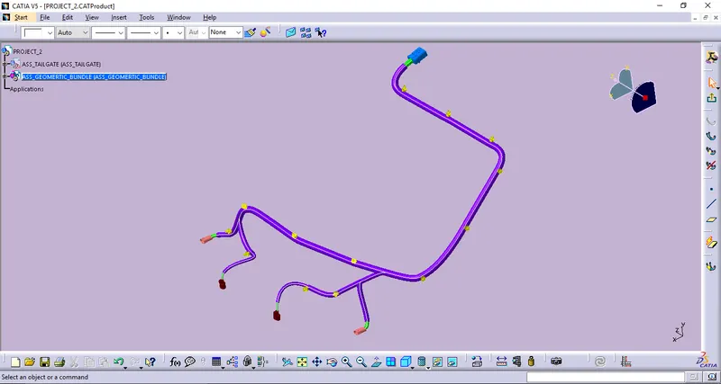
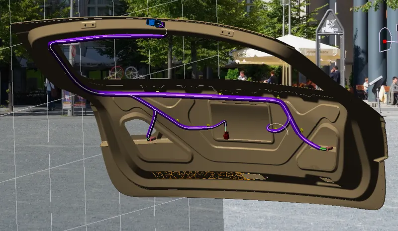
VIRTUAL REPERESENTATION OF ENGINE WIRIING HARNESS ASSEMBLY DESIGN
STEP_5: ELECTRICAL HARNESS FLATTENING
- Complete flattening of 3D electrical harnesses for manufacturing documentation according to user specifications.
- Manipulate bundle segments for flattening arrangement.
- Propagate modifications from the 3D harness design to the flattened harness including update of drafting documentation.
FLATTENING PARAMETER SETINGS
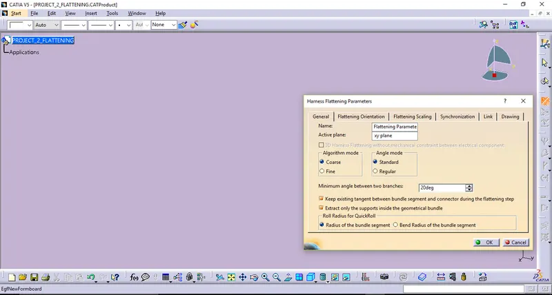
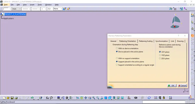

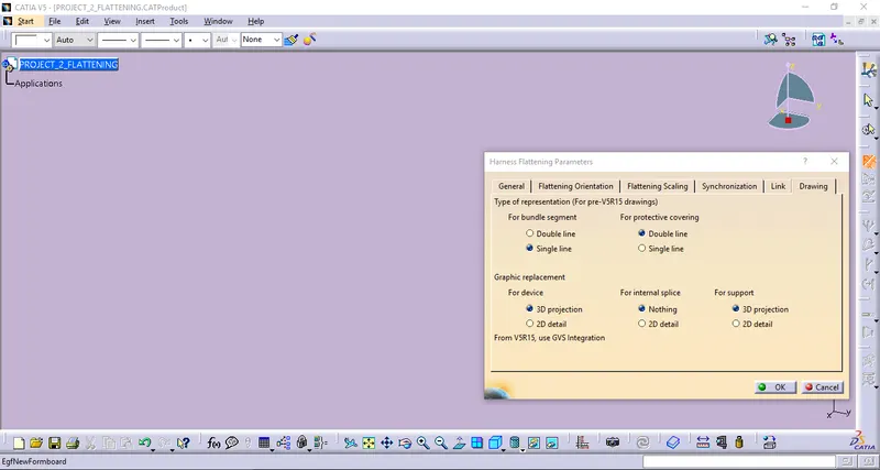
Commands used in Flattening workbench Extract, Flatten, Straight, Rotate, Bend, Arrang junctions & etc,.
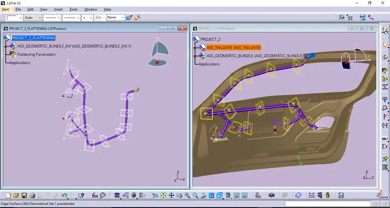
By defining extract command,
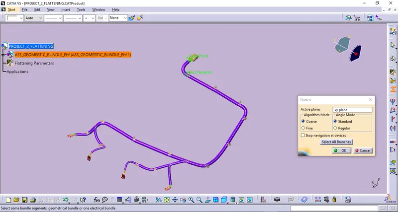
By defining flatten.
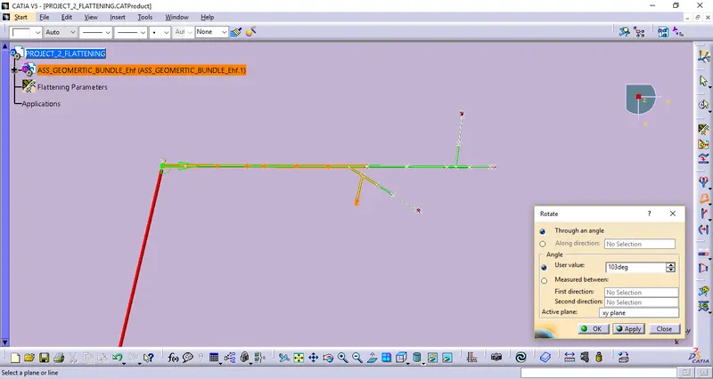
By defining rotate.
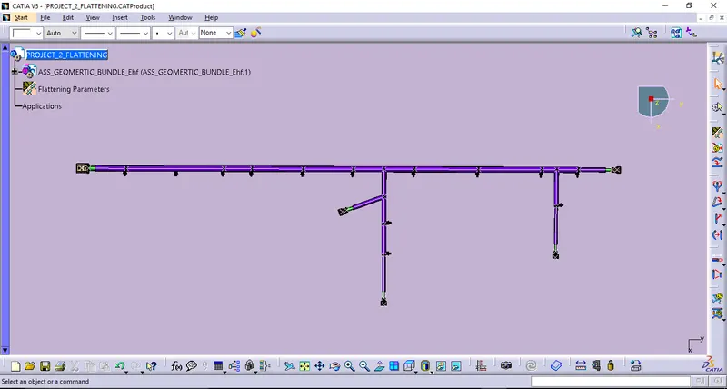
DRAWING SHEET:
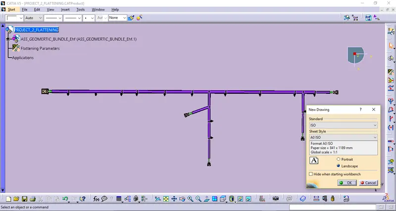
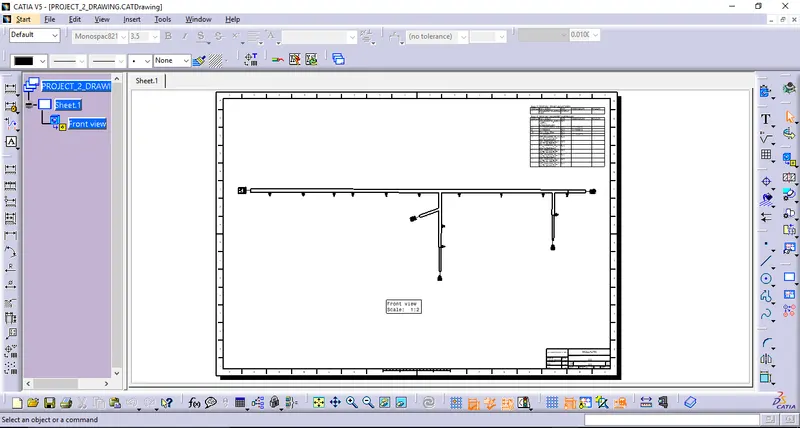
CONCLUSION:
Thus the routing wiring harness for the given car body(Tail gate) done by following all the packaging rules and design considerations by using CATIA V5.