SUV Tail lamp design using Catia V5
Objective:
To design a complete tail lamp assembly from scratch from given classA Surface with attachment features and positive mounting points with all child parts which includes housing, lens, reflectors and make an assembly and child part drawing of the same following industrial standards and ECE regulations.
Software used:
CATIA V5 R20
Introduction:
The lighting system of a motor vehicle consists of lighting and signalling devices mounted or integrated at the front, rear, sides, and in some cases the top of a motor vehicle. They illuminate the roadway ahead for the driver and increase the vehicle's visibility, allowing other drivers and pedestrians to see its presence, position, size, and direction of travel, and its driver's intentions. Emergency vehicles usually have distinctive lighting equipment to warn drivers and indicate priority of movement in traffic.
For the rear of a vehicle is provided by rear position lamps (also called tail lamps or tail lights). These are required to produce only red light and to be wired such that they are lit whenever the front position lamps are lit, including when the headlamps are on. Rear position lamps may be combined with the vehicle's stop lamps or separate from them. In combined-function installations, the lamps produce brighter red light for the stop lamp function and dimmer red light for the rear position lamp function. Regulations worldwide stipulate minimum intensity ratios between the bright (stop) and dim (rear position) modes, so that a vehicle displaying rear position lamps will not be mistakenly interpreted as showing stop lamps, and vice versa.
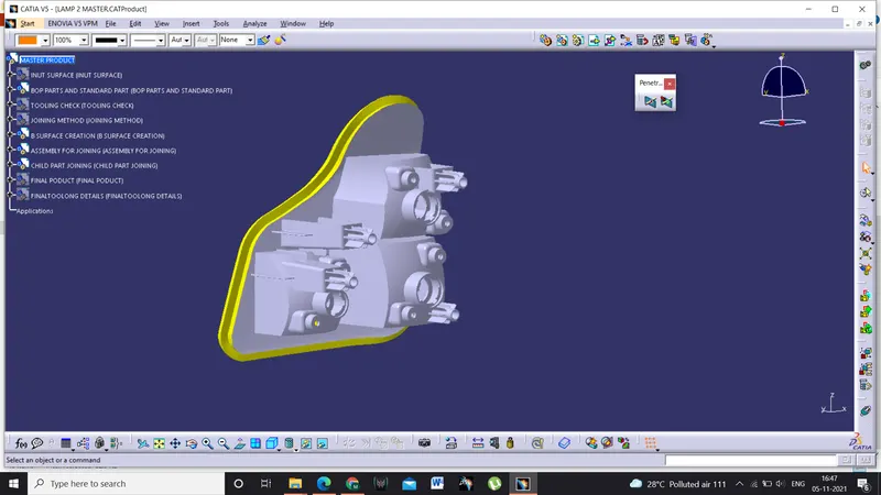
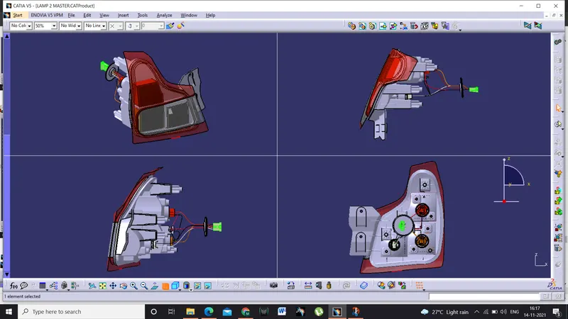
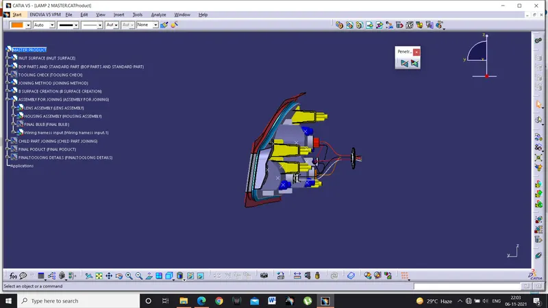
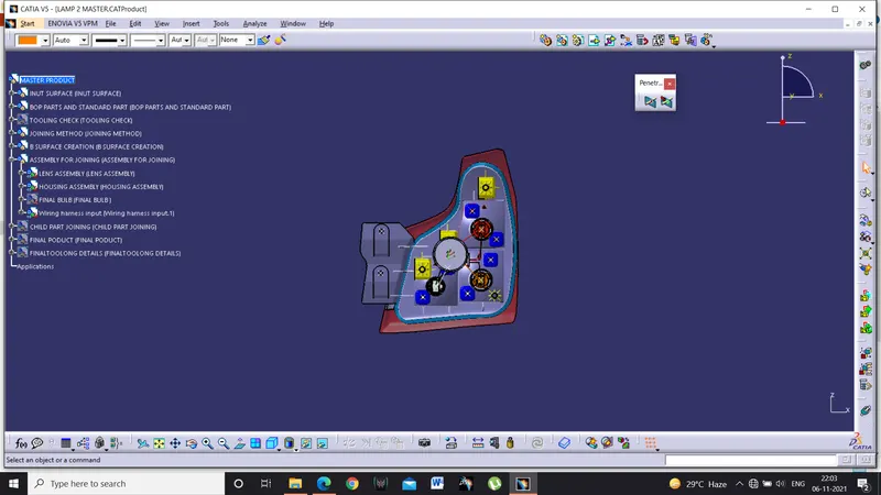
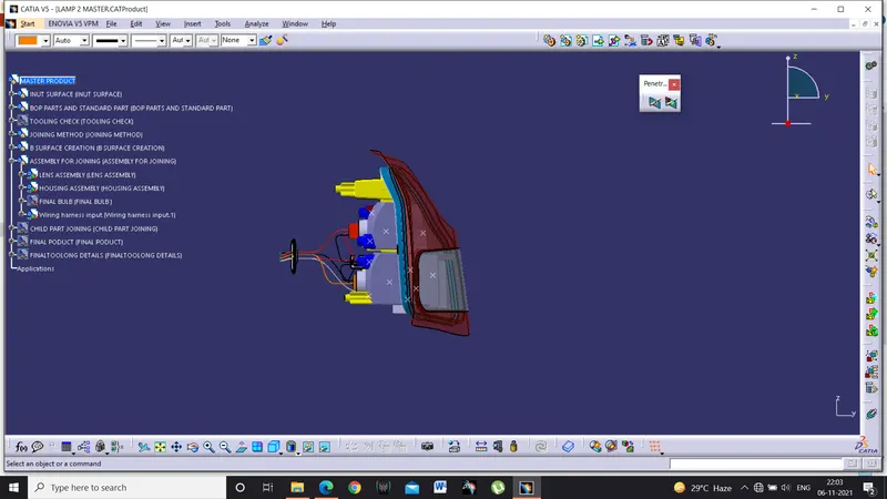
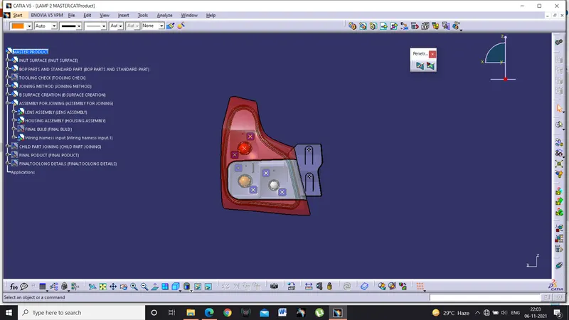
Following shown is the tail light designed using CATIA V5 following all lighting regulations
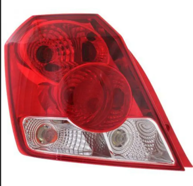
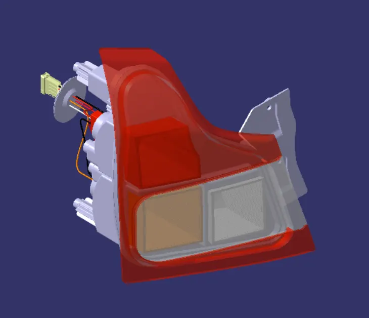
While designing the tail lamp following factors are taken into considerations
- Bulb used for all three functions
- Their focal points
- Wattage of bulbs
- Type of bulb
- Vehicle class
- Material to use for housing
- Material used for lens and reflectors
- Weld ability between materials
- Type of joining method to be used
- Standard parts and mounting points.
BULBS used in the lamp
Stop Function-W21/5W bulb
Reverse Function-W16W bulb
Turn Function-WY21W BULB
Housing Material -ABS(ACRYLONITRILE BUTADIENE STYRENE)
Lens Material-PMMA(POLY METHYL METHACRYLATE)
Reflector Material-PC(POLY CARBONATE)
Joining Method Used - HOT PLATE WELDING
Housing Thickness -2MM
Lens Thickness-2.5MM
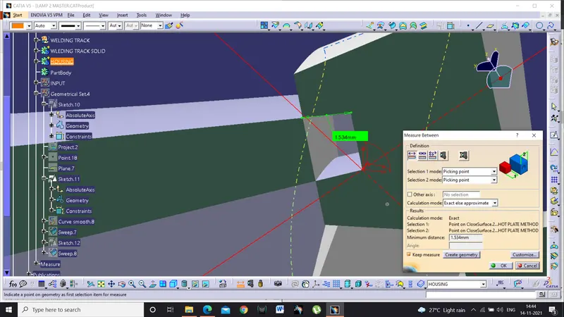
Lens And Housing Welding Track Interference-1.5MM
Start of making lamp
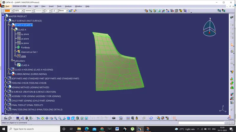
- First step is to clean the class A for any patches using join command by making sure that the merging distance will not cross 0.03mm as it would affect the surface quality of the lens.
- Make adjoin of the class A make it as publication
- Create a parametric tree structure using top to bottom approach including all the parts to be designed from start to end
- This would be very useful while making any changes to the class A and model and aids for quick update of the entire model
- Insert the class A part into the product.
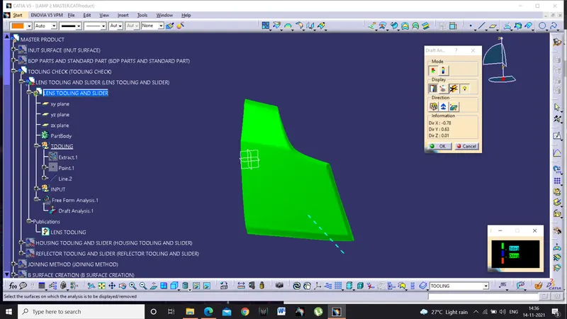
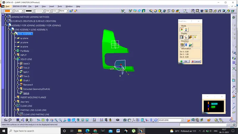
Determining tooling directions of lens using draft analysis
- By performing draft analysis we can easily determine the tooling direction so the A class surface
- Create a line normal to the class A surface and insert draft analysis to conduct the draft analysis with 3degree draft
- Make sure that all the surface are green and we are good to go
- If possible clear the tooling direction with general coordinate axis
- Here in this model the tooling axis is the Y axis.
Making lens class B surface
- Copy and paste special the class A publication inside the parametric model under class product file
- Extract the class A as we don’t want to touch the class A
- Make a offset for 2.5mm ,if offset don’t work try making rough offset and extract the boundary of the class A
- Make a swept surface with boundary a s guide curve and tooling direction as draft direction with 3ddegree draft
- Cut the surfaces as make a close body.
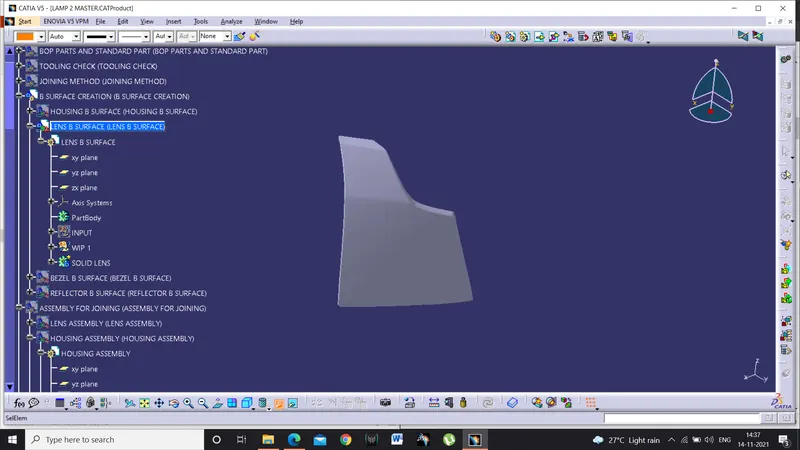
- Insert a boys and make it as publication lens class B surface
- We have only red lens but we have three functions to perform those are
- Stop function
- Reverse function
- Turn function
- Only stop function needs red light reaming light have to be clearly indicate the amber and while colour so we create a clear lens to make the indication of colours clearly.
- here we can use red light for tail stop but PR21W bulb is very costly , so to reduce the cost of th lamp we use insert molding and red lens.
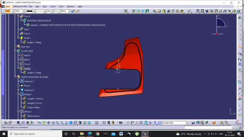
- So we create insert moulding section to make the clear lens attached with the red lens
- We create the section and we add it to the clear lens and remove it from red lens.
- In insert moulding first the clear lens is moulded and then the clear lens in placed in another mould and red lens is moulded on the clear lens
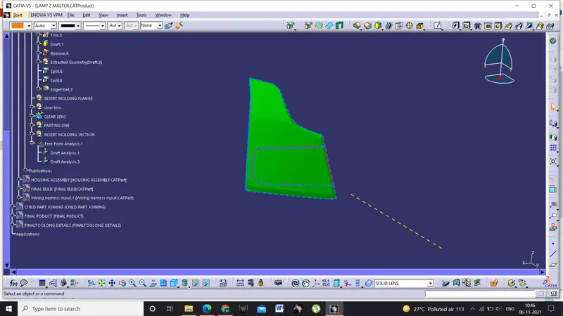
- Perform the draft analysis and parting line is extracted and published
- Lens is completed and ready for drawing
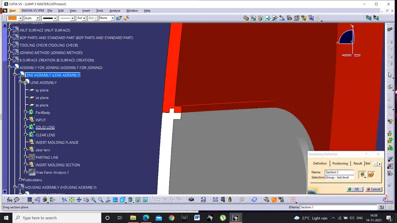
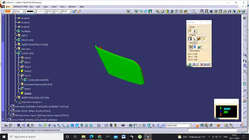
Joining method
- Here we use PMMA for making lens as it has more transparency and comes with hard coating which protects the lens from sunlight
- PMMA can go under hotplate welding and vibration welding
- Here we choose hot plate welding for making the welding section as the lamp size is big and it would be difficult to use vibration welding process
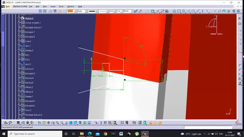
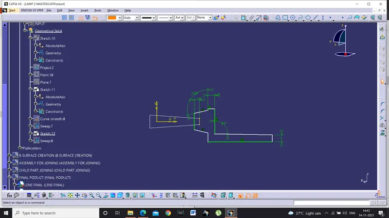
- The section for the welding track is prepared based on the thickness of the lens
- Make a parallel curve with 10mm from the extremer edge of the lens
- Make it a smooth curve using smooth curve definition
- Using the sketch as profile and smooth curve as the guide curve
- Make it as solid body
- Union trim it with the lens solid and we have the welding track for the hot plate welding.
Making reflectors
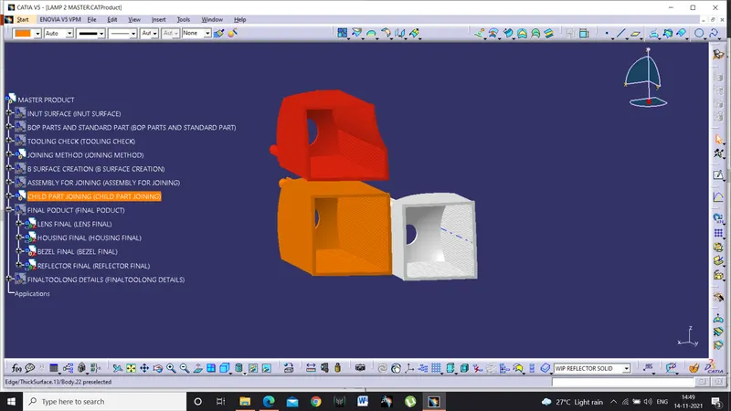
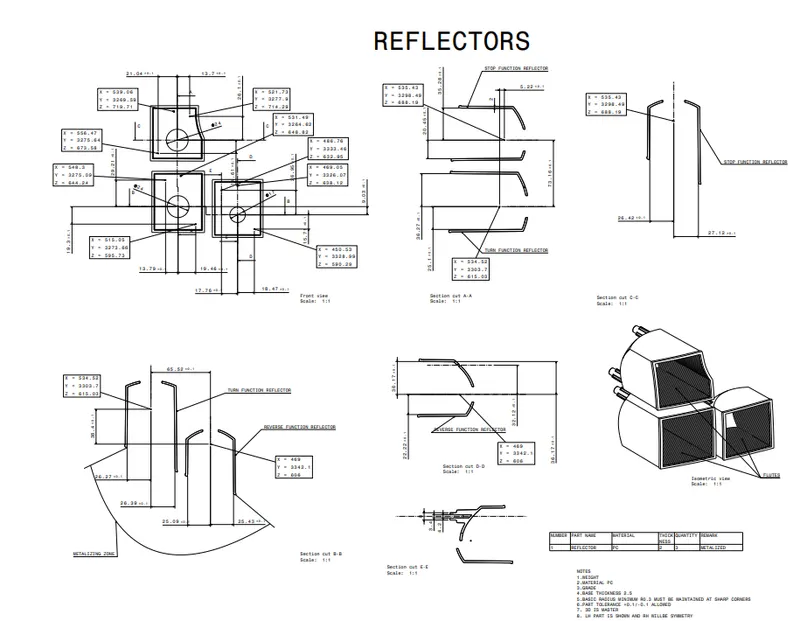
- Reflectors are the child part in which the optics are installed which enhances better lighting and aesthetics of the tail light
- Before making reflectors we have to decide where to keep the reflectors and at what distance
- Using data from the bulb we get the focal points of t bulb
- Now create points on the surface of the lamp
- Make a line with Y axis ot55-60mm from the lens and make an axis system at each of the points
- Now we get to know where to position the bulbs
- Using axis to axis translation bring the bulbs to the focal points
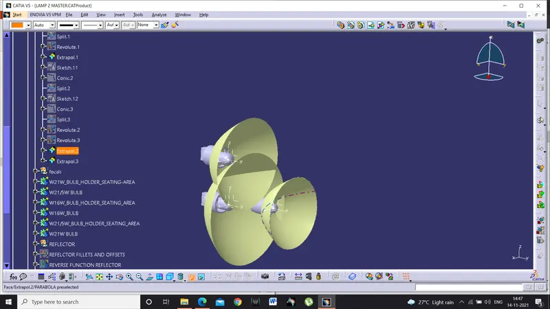
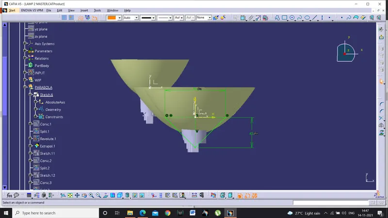
- Now sketch the parabola and using conic make parabola
- Using extrapolate the edges
- Now from the axle centre check the height and distance between lamps
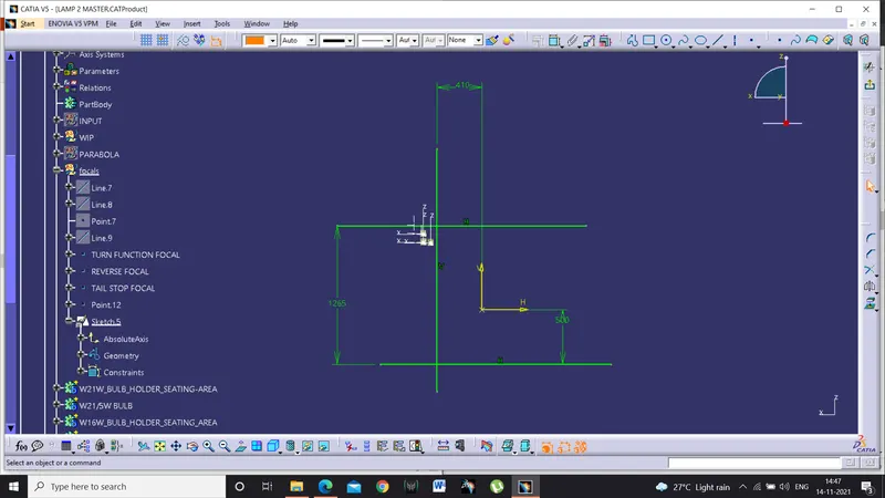
- According o ECE R48,R23,R7,R6 ,The maximum height at which the tail lamp should be position is 1500mm from the ground plane, the ground plane is taken at 500mm away from the axle centre
- And from the centre it should be minimum 600mm
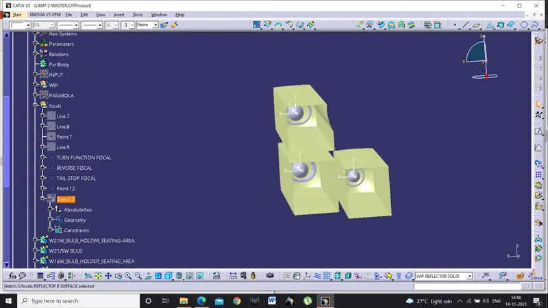
- So we make the sketches and make extrudes
- Make the trims with parabola and make publications
- Use thicken and make solid for all reflectors and publish them
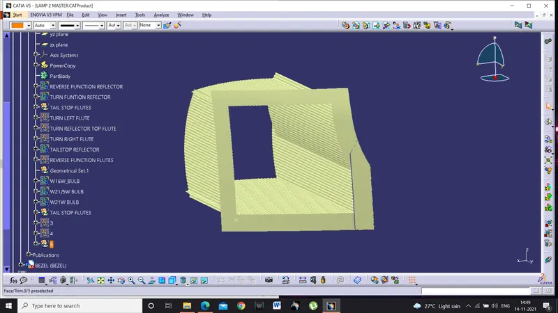
- To add more reflecting surface flutes are created on the walls of reflector using power copy
- Reflector faces are extracted and at distance of 2mm the b surface is offseted and curves are projected to create flute
- After one flute is created insert >knowledge template>power copy and select the inputs
- Select the inputs and perform power copy to get flutes all over the surface of the reflector
- Thicken the flutes and union trim with reflector.
Making housing
- To make housing we need reference sections through which we can get an idea of how will the housing will look like
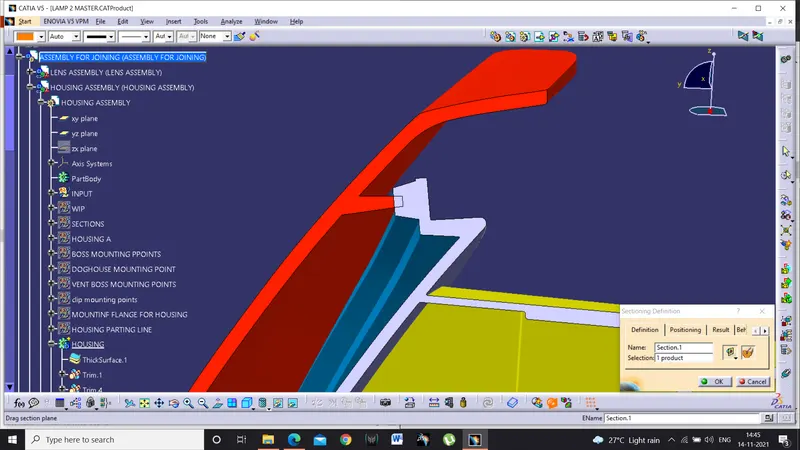
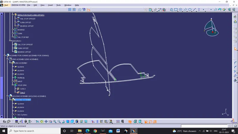
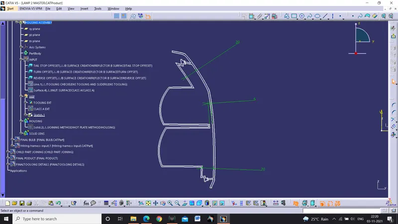
- To make those sections make a intersection of class A reflectors and welding track section
- We get a rough section later we modify the housing section accordingly
- Where the reflector meet lens there should be offset of 5mm to avoid the light bleeding
- And rest other places can have 15-20mm offset
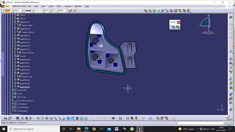
- Using the section we make the housing class A
- Make a offset of class A and using swept close the open boundaries
- Use close body and make a solid body.
Making housing welding track
- We have completed the housing and lens
- Now to create a sketch which we take reference from the lens welding track and we must have an interference of 1.5mm with lens welding track
- Make a sketch and create sweep with draft direction with boundary as guide curve and sketch as profile
- Make a solid of that
- Union trim the housing solid with the welding track
- And housing is ready.
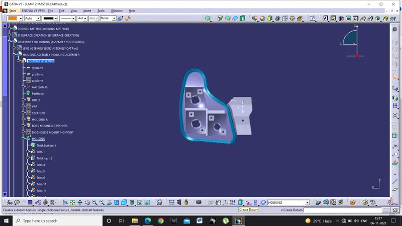
Making attachment features and mounting flange
- To attach the tail lamp to the car body a positive mounting should be designed
- It will be input as BIW or we can create a reference surface and use it as biw panel
- Design a mounting flange and create an area to mount the M5 screws and make a slope so that the water can slide through that slope
- Make a solid of the flange and union trim it with the housing
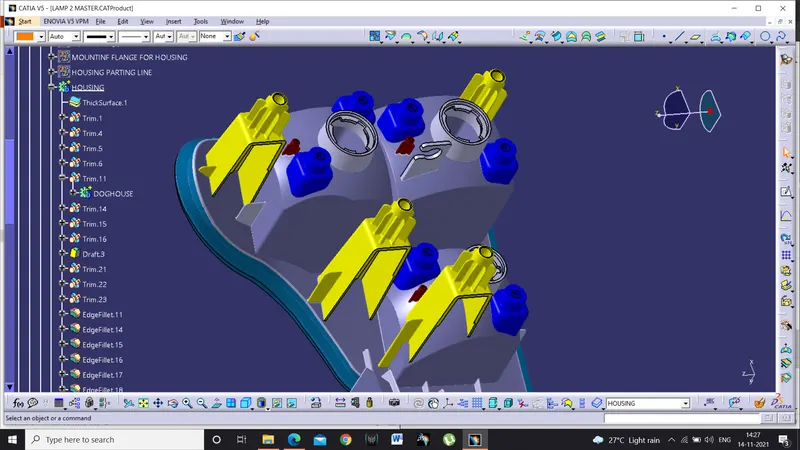
- Create dog houses and screw bosses to mount on the reflectors with the housing
- Doghouses are created to avoid sink marks and reduces the sudden flow of plastic avoidong the plastic defects.
- To add extra strength to the housing add ribs wherever required and make union trim
- Create points on the housing and make them as co-ordinates and create a new axis system over there.
- Copy the doghouses and paste special in the part with result to link
- Perform axis to axis translation and union trim with the housing
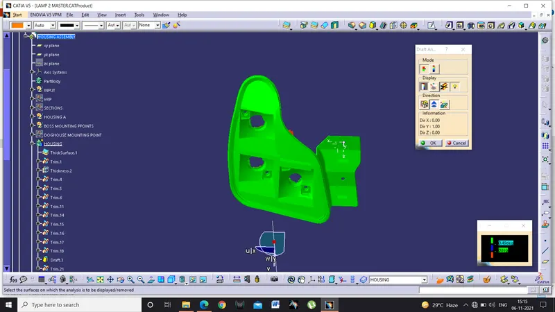
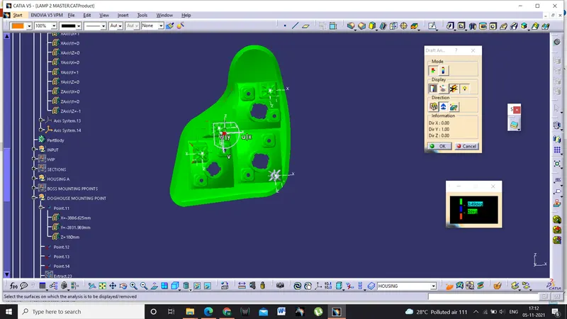
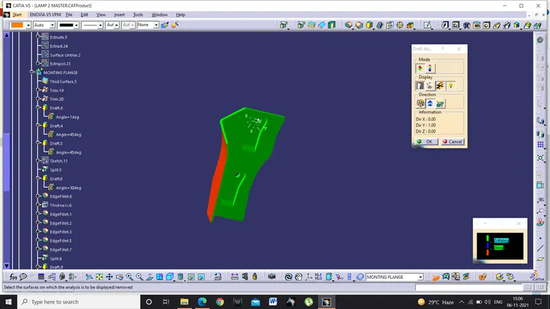
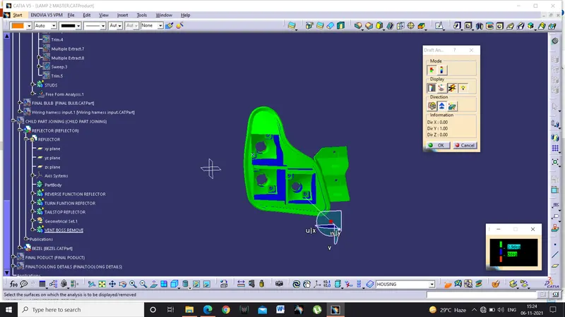
- Perform draft analysis and extract the parting line and publish it
- The doghouse needs a tooling direction as it can’t be cleared with main tooling direction
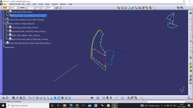
- Publish the dog house tooling direction and main tooling direction.
Creating wiring harness:
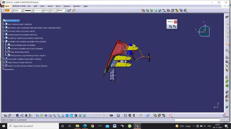
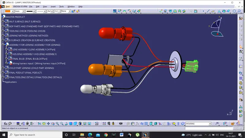
- Wiring harness is the wiring structure that protects the lights from outside environment and water
- We create a grommet so that the wiring can be separated from inside the housing and from outside
- The water slides and stops at the grommet and prevents the water entering the housing.
- A routing feature is created to keep the wires held in place and helps the wires get not tangled
- Given connector have 6poles and we have 7 poles for the lights , we have common wire for earth which is black
- Tail stop and tail function have same pole.
Creating vents for reflector
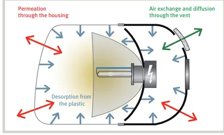
Plastic cap vents to block water and dust ingress inside the lamp are called vent caps. Headlamps and tail lamps have to cope with environmental conditions that change every day. What’s more, they have to be protected against dust, dirt, deposits, and condensation if they are to work effectively and guarantee drivers a clear view at all times. Various options are available to automobile manufacturers and suppliers for removing moisture from headlamps. When selecting a venting membrane as an option, the solution must be able to equalize pressure within the headlamp housing, form an effective barrier against dirt and water ingress, and be able to reduce condensation.
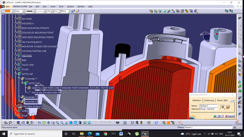
- We have to design a vent cap seating area to the vent cap to sit on
- These vent cap seating area are mounted exactly top of the bulb as the heat always flows in upward direction and escapes through the vent wholes
- These caps protect from the dust and moisture entering into the lamp.
- Vent cap mounting should be placed in such a way that it be accessed easily and installing and removing vent cap should be easy and must not obstruct the operator while installing the lamp.
Lamp finishing
- There should be no sharp edges in the model so applying fillets would give good look and better plastic flow
- Minimum 0.5mm fillet should be given
- Make sure there are no sharp edges and add draft where ever needed
- Perform draft analysis and finalize the model for drafting.
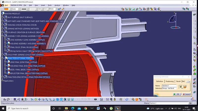
Finally add the final lens and housing into the final product file and add final parting lines and tooling direction to the final tooling details.
Making assembly and child part drawing
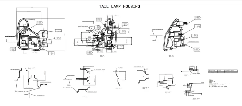
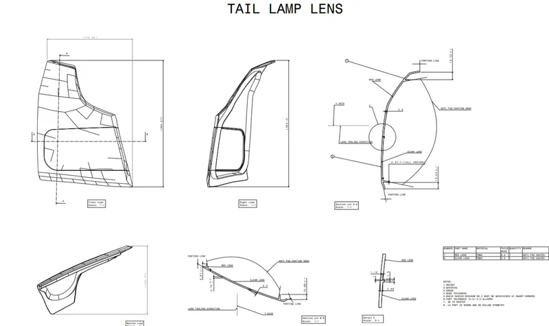
- Drafting helps the designer to check the regulations and it also helps the tool maker how the section of the lamp is and quality people will check the model using the drawings given the design team
- While we make drawing of the housing , to make the housing visible in the drafting workbench we use link modification to do the job
- If we want to make the studs and other component from all views overload properties command can be used
- These are very handy while making assembly and child part drawing.
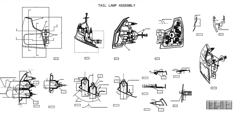
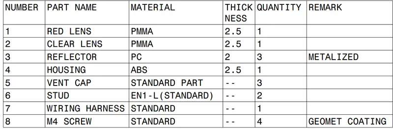
- While making assembly drawing there should be no mistake as these Ares submitted to the OEM and the details include should not be very detailed and must consist all details like materials, regulations, and bill of material and should be clear to understand.
- The assembly and child part drawings are shown below.
Conclusion:
- The complete tail lamp is prepared as per the industry standards with positive mounting flange and welding section is created for hot plate welding.
- Attachment features are created on the back side of the housing and ribs are added to add the strength to the housing
- Parting lines are determined for lens and housing and draft analysis is done.
- BOM is prepared for the assembly
- Assembly and child part drawing are created.