Project 2
The routing is to be done on a backdoor of a car.
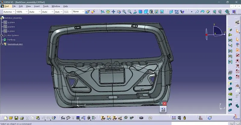
For this backdoor,three 4 pole connectors,one 2 pole connector and one interconnector are used.
Two 4 pole connectors are used for the right and left brake taillight.
One 4 pole connector is used for the top mounted back light,one 2 pole connector is used for the wiper motor.
The interconnector is used to connect the entire wiring harness to the main wiring harness.
The required connectors are downloaded ,given geometrical properties and defined as connectors,they are also added to the catalogue.
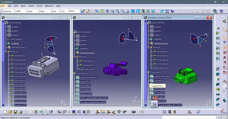
adding to catalogue
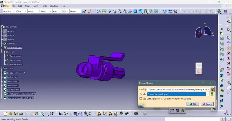
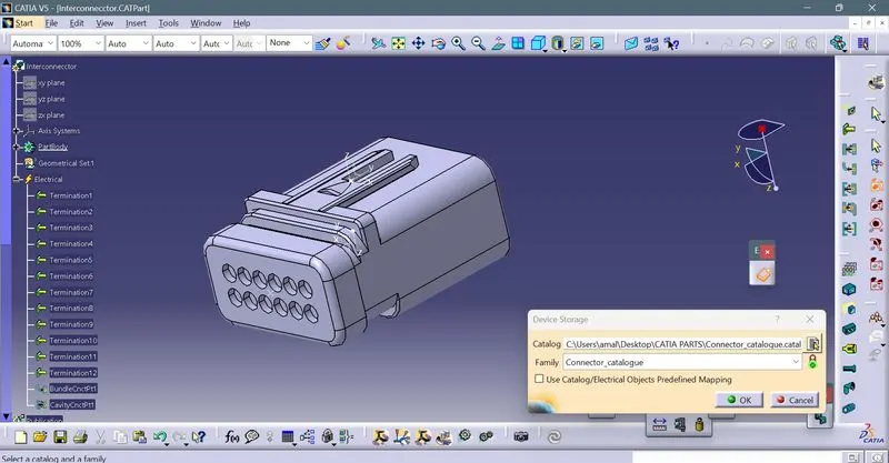
After that ,fir tree clip and interconnector mount are downloaded and defined as support parts for the wire routing.
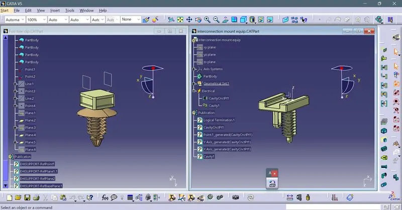
A product file is created, named backdoor assembly geomterical bundle in which all the connectors and support parts are placed.The backdoor_assembly and backdoor assembly geomtrical bundle are placed in another product file named backdoor assembly project.
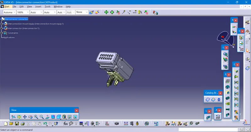
The interconnector and interconnecor mount are joined using connect electrical devices option in electrical part design window.Both are placed in file named interconnection connection and is placed in backdoor assembly geometrical bundle.
The connectors are placed on the appropriate positions of the backdoor.
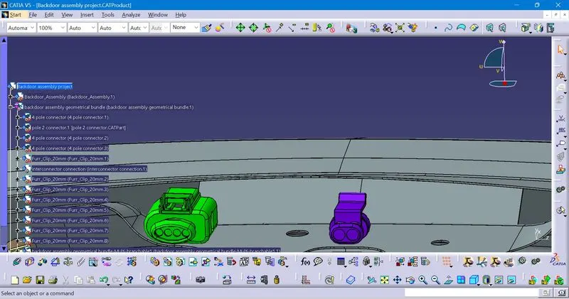
one 4 pole connector for top mounted brake light and 2 pole connector for wiper motor.
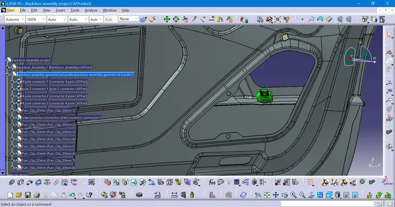
one 4 pole connector for right side tail light brake.
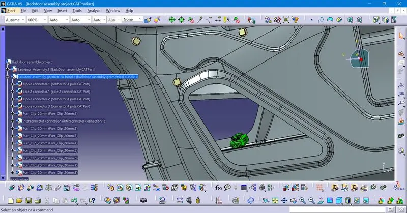
one 4 pole connector for left side tail light brake.
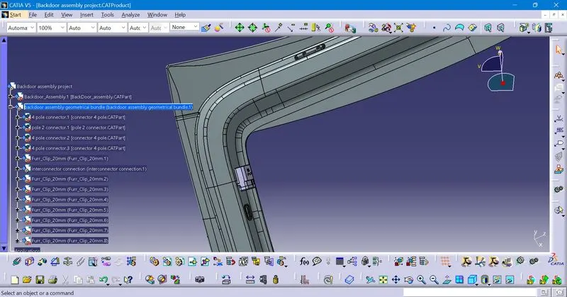
Interconnecor is placed using the interconnector mount on the top left side.
After keeping the connectors ,all the fir tree clips are placed .They are placed according to the guidelines,that distance between the clips should be 50 - 200 mm.
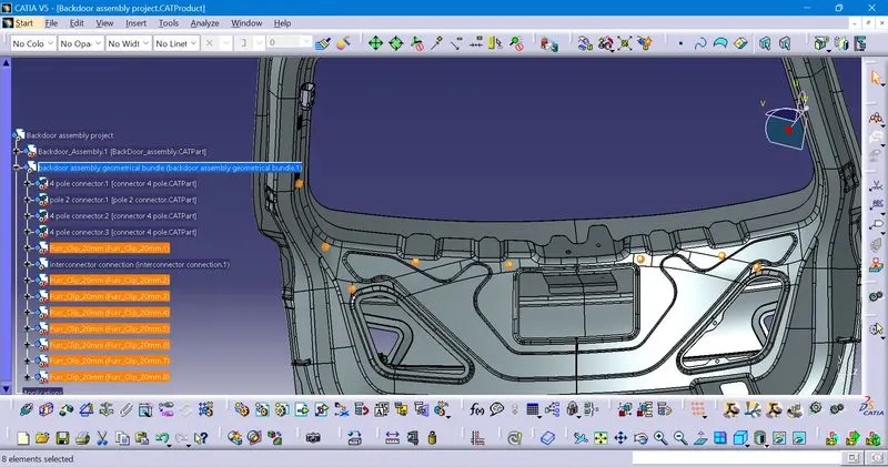
After all the proper placement is done,the wire routing is started.
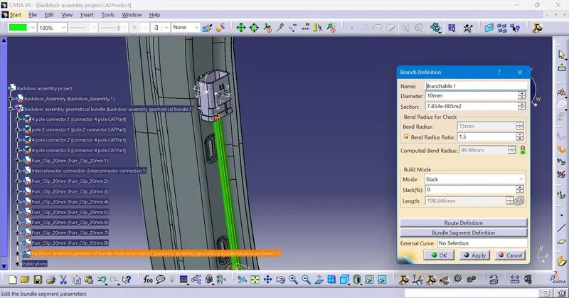
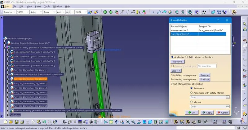
In branch definition,the diameter of the wire is specified.Route definition is done by selecting the points .
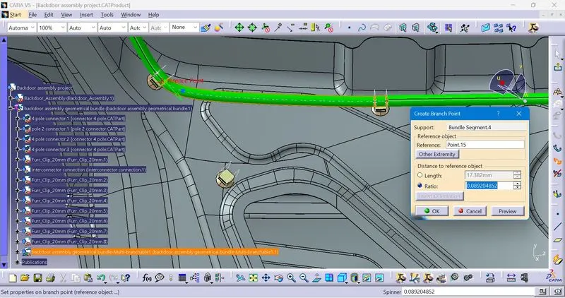
Branch points are also created on the wire,to take the wire of required diameter.
The wires which are connected to the connectors are given wire diameter 5 mm.
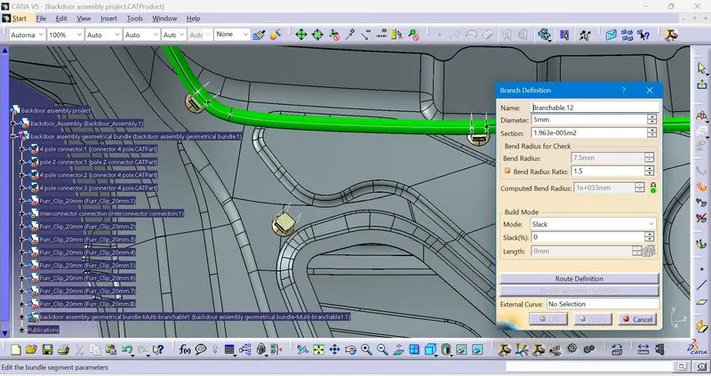
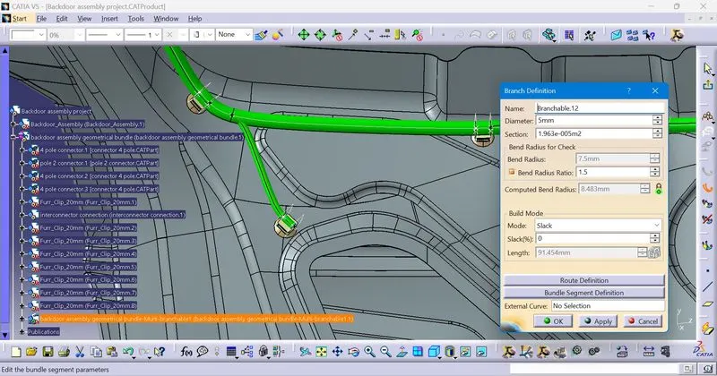
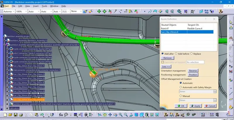
Slack is given wherever required.
For the top mounted brake light connector and wiper motor connector wiring,a slack of 20 percent is given
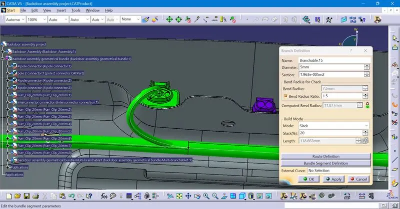
Like that ,all the routing is done.
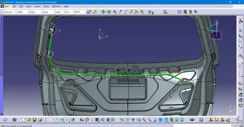
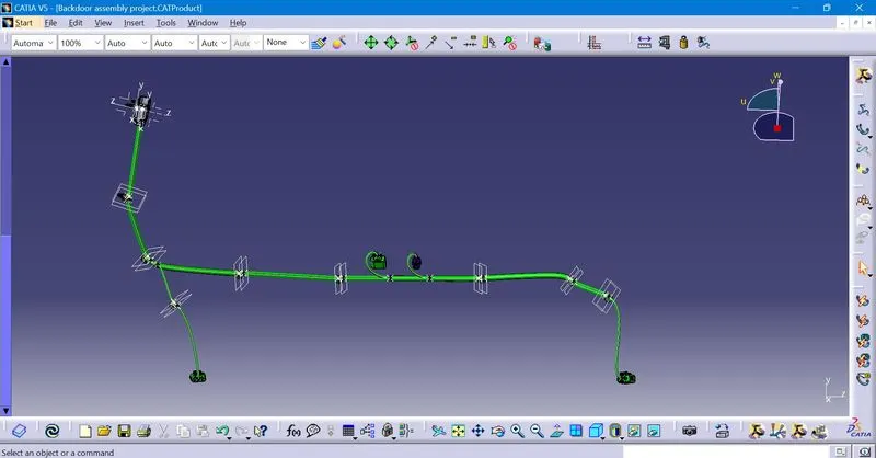
The connectivity is checked,by going to edit ,search and searching for fully connected.
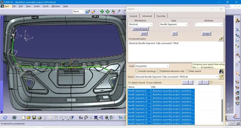
This shows that all the bundle connectivity is complete and there is no disconnect.Also in the false option,there is no object shown,which also shows that there is no disconnect.
After that,protective covering is given to the wires.
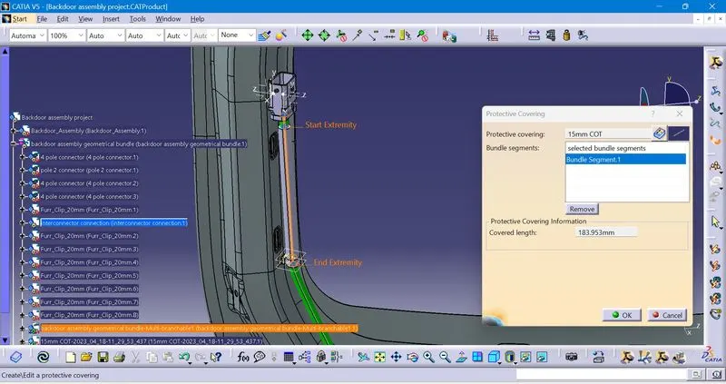
From the extremity to connector ,a distance of 15 mm is taken.
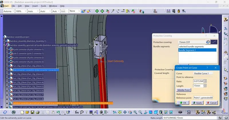
This is the final completed wiring harness routing with protective covering.
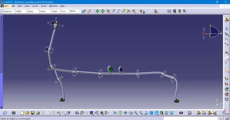
After the routing is completed.
The wiring harness is going to get flattened.
go to file,new,product and go to flattening window.Set the flattening parameters.Then click extract and select the wiring harness.
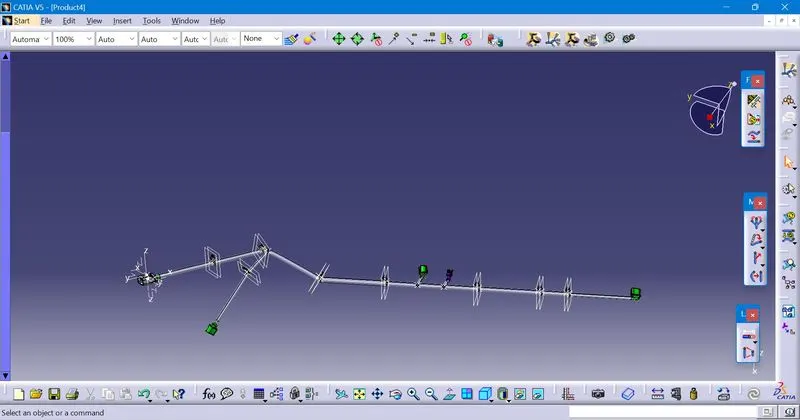
Using the compass,rotate option and straighten option ,the branches are aligned.
This is the final flattened wiring harness
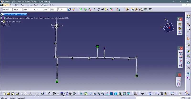
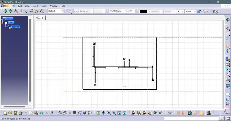
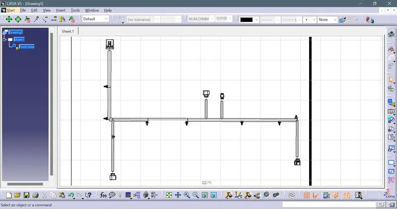
After the flattening is completed,the drawing is to be made.
Go to file,new,drawing.Select landscape.
In the drawing window,click front view and click on the flattened wiring harness.
Then correctly align the drawing.,also select the required options in the properties option.