Project 2
Develop general arrangements for the RC office building. Analyze and design the building as per IS standard code in TEKLA STRUCTURAL DESIGNER. Refer to the attached plan and elevation. The building to be designed for dead, live, wind, and seismic loading.
Report of each member to be generated and extract drawings for structural plans, beam reinforcement details from the software
ANS:
AIM: To develop the general arrangement for the RC office building, analyze and design the building as per the IS standards, and design for dead, live, wind, and seismic loadings.
Tools Used: Paint, manage property sets, construction levels, and grids, beams, columns, slab, wall panels, loads, load cases, seismic wizard, model report, show report, roof panels, etc.,
Procedure:
Step1: First a rough drawing representing the positions of columns and beams is done.
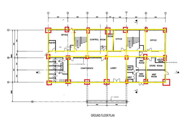
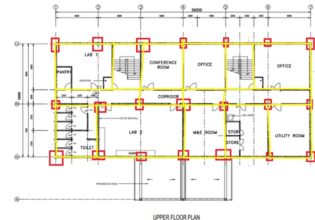
Step2: Open a new Tekla file and save it in a specific location and with a specific name.
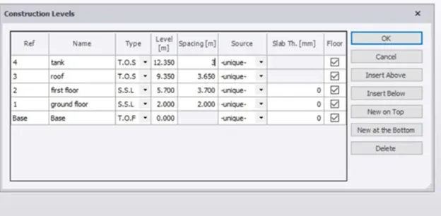
Step3: Create construction levels according to the plan.
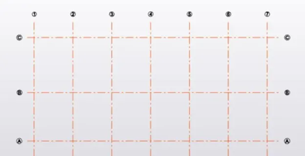
Step4: Now create grids according to the floor plans given.
Step5: Now create materials required for the modeling of the structure using manage property sets.
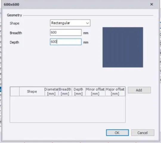
Step6: After the creation of column property model them according to the plan.
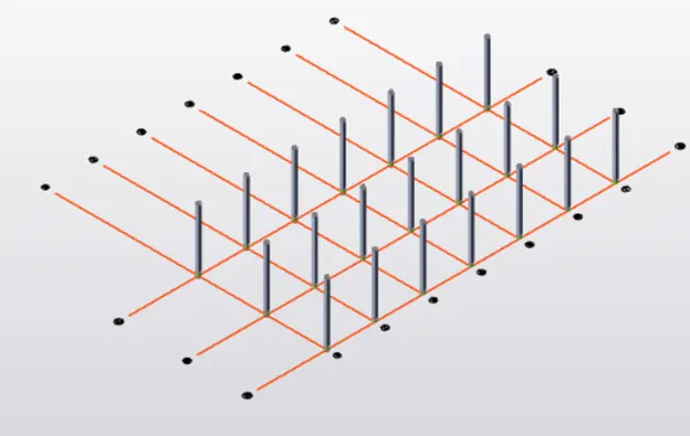
Step6: Now create the beam property and assign them accordingly.
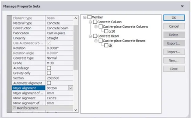
GROUND FLOOR
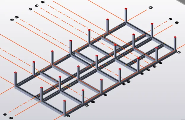
FIRST FLOOR
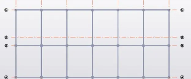
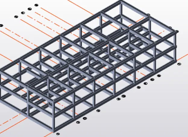
Step7: Now create slabs in the plan accordingly and apply loads.
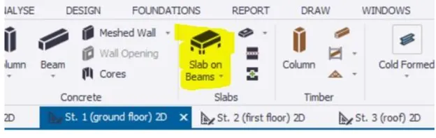
Step8: As the structure is modeled now calculate the loads according to the IS codes and assign them accordingly.
DEAD LOADS: According to the IS 875-part-1 the dead loads on the structure are:-
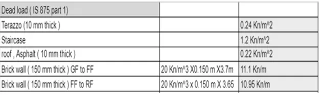
Step9:
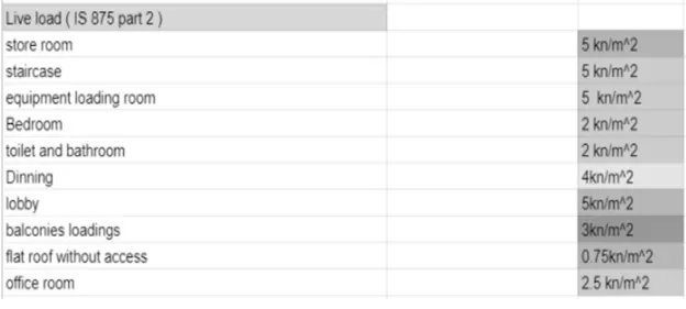
LIVE LOADS: According to the IS 875-part-2 the Live loads on the structure are:-
WATER TANK LOAD/ SERVICE LOAD:

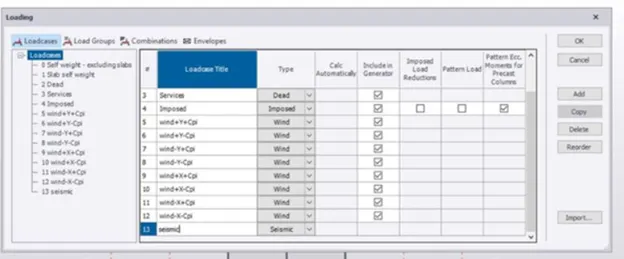
Step10: Now we have to add to the model. Before that, we have to create the load cases.
Step11: Now apply all the dead, live, and service loads on the model created.
Dead Load:
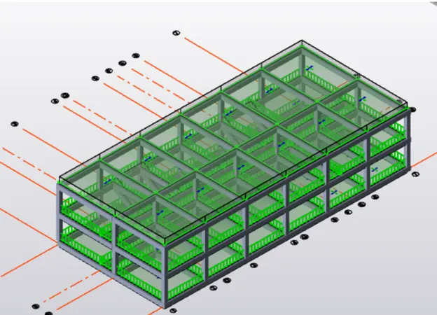
Live Load:
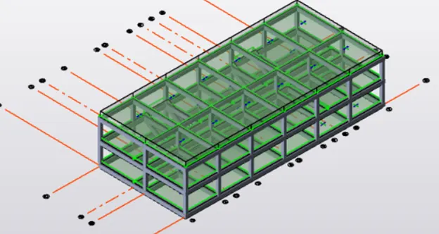
Service Load:
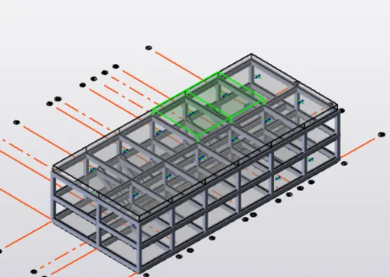
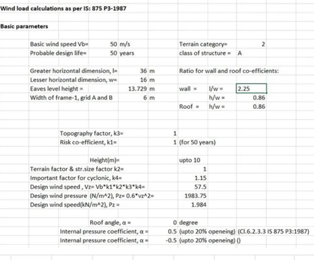
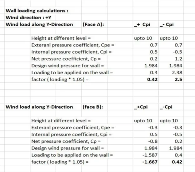
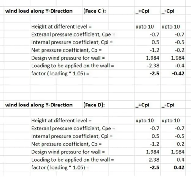
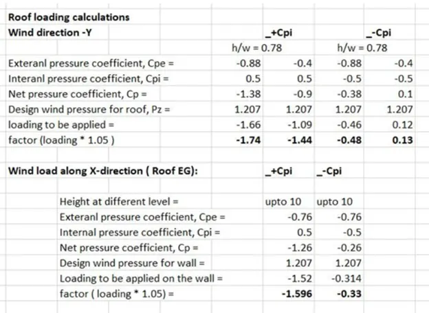
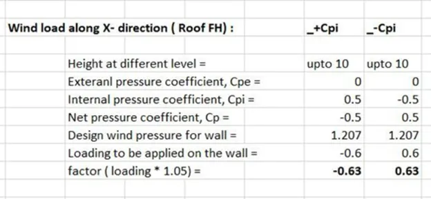
Step12: Now calculate the Wind loads according to the IS 875 Part-3.
Wind Load Calculations:
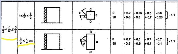
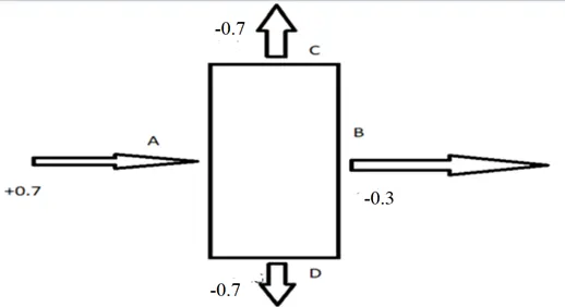
Step13: Before wind application, we have to create wall panels.
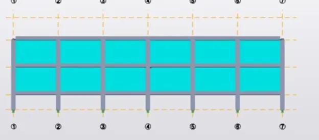
Step14: After the creation of wall and roof panels now start applying the Wind Load on both the wall and roof Load which is calculated.
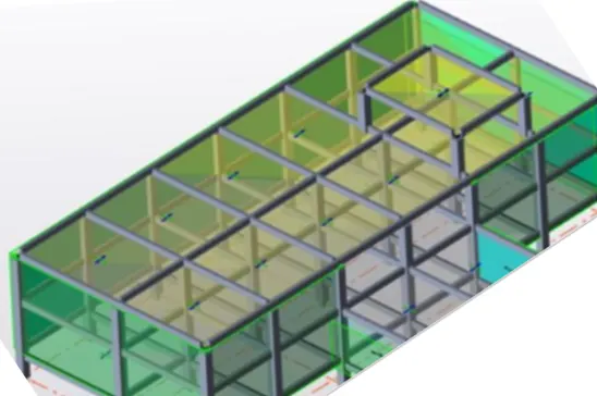
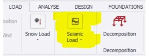
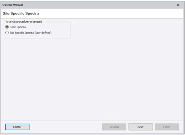
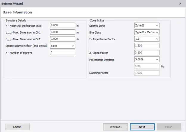
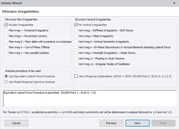
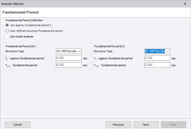
Step15: Now after the Wind load application apply seismic load using the wizard and do accordingly.
SEISMIC LOAD:
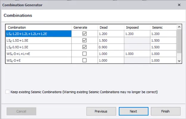
Step16: Now create the load combinations according to the loads created.
Step17: Now Validate the model after the application of the seismic Load and then do the analysis.
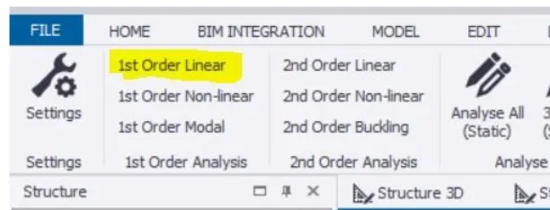
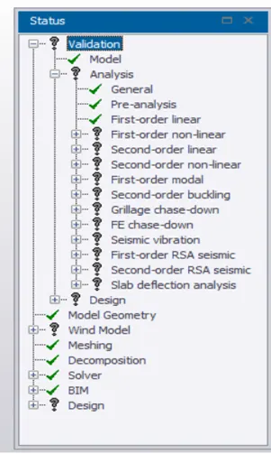
Step18: Now check for results like axial load, moments, Shear force, and Deflection.
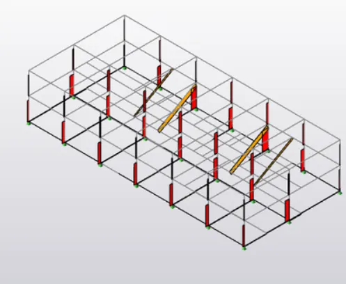
Step19: After the analysis, the interactive design of the Beams, columns, slabs are done.
Step20: Click on any column for interactive design.
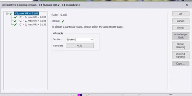
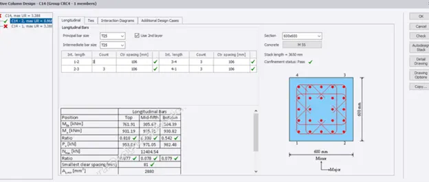
Step21: If any error is there, then rectify them by changing properties.
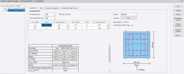
Step22: Now go to results view and check for Slab design
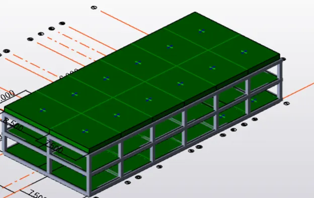
Step23: Now design the foundation.
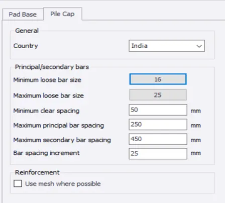
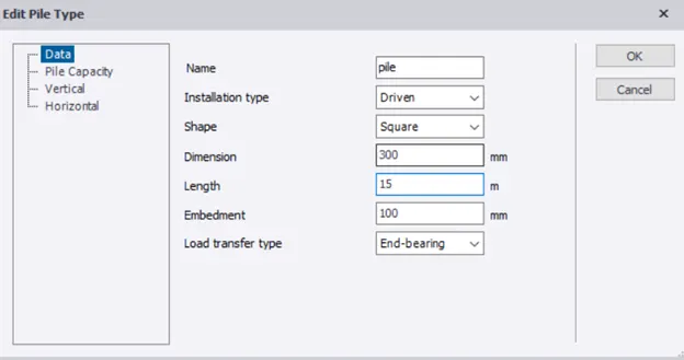
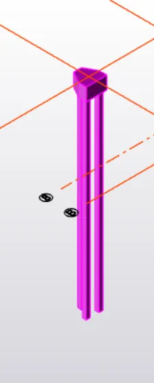
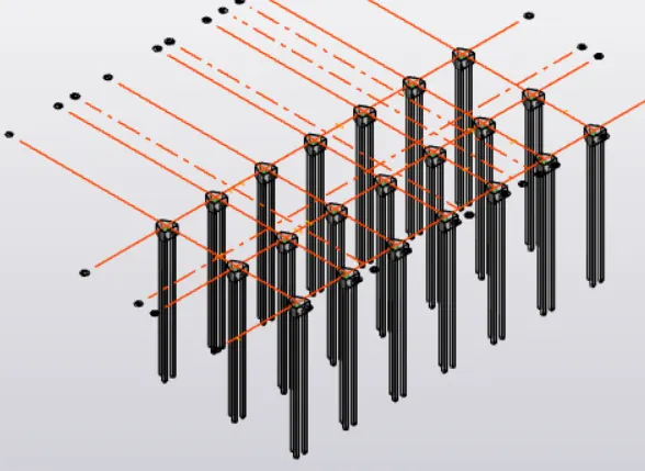
Step24: If we had modeled all the foundations then we can check for foundation design.
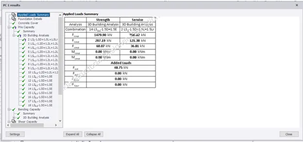
Step25:
REPORTS:
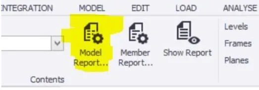
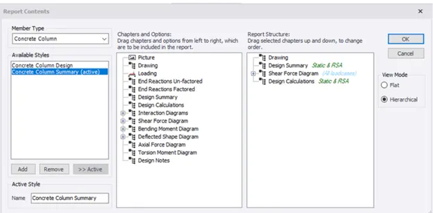
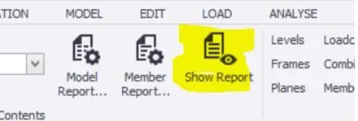
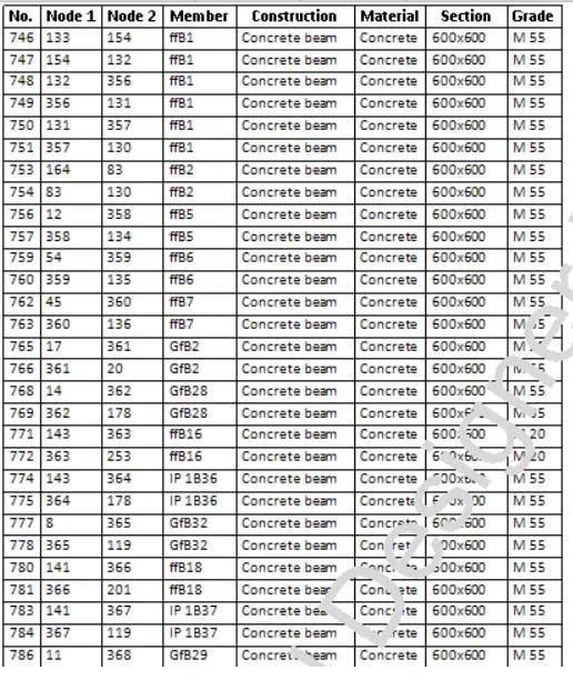
If we get the report by modeling it according to the requirements required in the report. This is done by clicking model report then selecting the fields required in the report next show the report.
RESULT: Hence design and modeling of the RC building has been done successfully. The analysis was also done by including dead, live, wind, and seismic loads according to the IS standards. Finally, reports had been generated and extracted.