Project 2
Objective:
Development of forward energy based fuel consumption model of a P1 architecture Hybrid vehicle. We have an initial data of a Honda insight motor and battery. And these data is taken from Advisor model developed by NREL, USA.
Based on the initial data and details provided we need to model a P1 Hybrid architecture vehicle model using matlab and simulink.
The aim of the project is,
- Model P1 Hybrid architecture using Simulink.
- Run the model to get the results and plot them for study.
- Compute the different operating variables like speed, fuel economy, battery conditions etc.
- Compare the results with conventional vehicle model and list the comparisons and advantages.
Problem Statement:
We have provided data for Honda insight motor and battery details taken from Advisor model. We need to create a forward energy based fuel consumption P1 architecture hybrid model using Simulink for the study and comparison. We have already done conventional vehicle model and have the results and data. We need to use these data for the study and comparison and draw advantages of hybrid drive over conventional vehicle model.
After completing the model we need to simulate and get the following results.
- Plot and tabulate the fuel economy numbers for UDDS and HWFET drive cycles and compare these numbers with model which we had done for conventional vehicle.
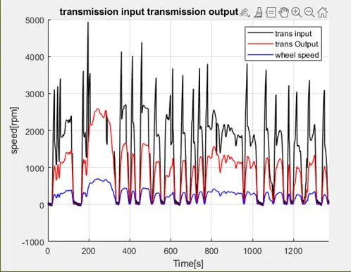
- Plot time trace for engine, transmission input output and wheel speed
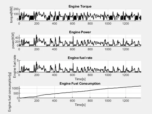
- Plot engine torque, engine power fuel rate and fuel consumption using subplot.
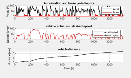
- Plot acceleration, brake, gear command and vehicle speed and distance covered using subplots.
- Plot motor speed, torque and input power using subplots.
- Plot pack current, voltage and SOC.
Theoretical study:
Types of Propulsion Models
Based on energy source used for the propulsion we can classify the vehicle models as below,
Conventional vehicles use an internal combustion engine fuelled by gasoline or diesel to power the wheels. Electricity is used for some accessories, but is not used to move the vehicle.
Vehicles can be powered in several different ways, from gasoline to electric batteries and a spectrum of choices in between.
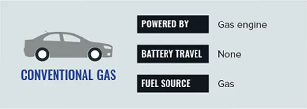
Fig 01. Conventional Vehicle
Conventional hybrids, also referred to as hybrid electric vehicles (HEVs), supplement the internal combustion engine with electrical power produced by an on-board electric motor. The electrical system acts as a generator when a driver applies the brakes, converting kinetic energy into electrical energy that is stored in a small battery pack. The primary fuel is gasoline or diesel.
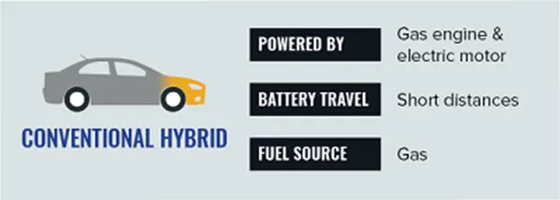
Fig 02. Conventional Hybrid
A plug-in hybrid, also called a Plug-In Hybrid Vehicle (PHEV) or an Extended Range Electric Vehicle (EREV), has a larger battery than a conventional hybrid car, and is charged by plugging into an electric outlet. Plug-in hybrids also keep a gasoline or diesel engine as a backup. After the battery energy is exhausted, the engine starts and the vehicle acts like a conventional hybrid until it is plugged in to recharge.
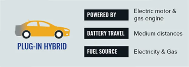
Fig 03. Plug in Hybrid
A battery-powered car, or Battery Electric Vehicle (BEV), does not have a gasoline or diesel engine and instead has an electric motor, power electronics, and a battery pack. Battery cars have a longer all-electric range than a plug-in hybrid, but they do not have a fuel backup. Just like a plug-in hybrid, battery-powered cars plug into an electric outlet to refuel.
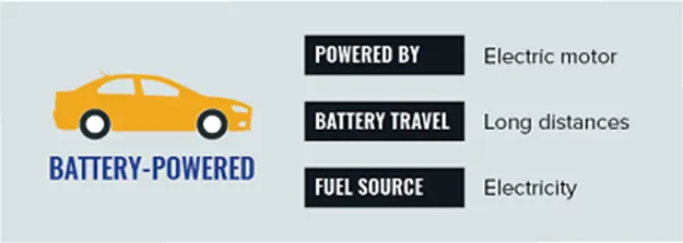
Fig 04. Battery Powered
Hybrid Vehicle Drivetrain:
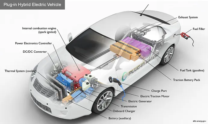
Fig 05. Hybrid drive vehicle
A hybrid electric vehicle (HEV) is a vehicle which is using two sources of energy for propulsion, one of them being electrical energy. Most of the road vehicles with hybrid powertrain use an internal combustion engine (ICE) combined with an electric machine (EM).
Compared with a conventional vehicle, powered by an ICE, a hybrid electric vehicle is capable of performing these functions:
- fast ICE stop & start
- energy recuperation during braking (regenerative braking)
- torque assist/boost
- electric driving
- coasting (optional)
Parallel Hybrid powertrain:
In a parallel hybrid powertrain, both the internal combustion engine and electric motor can transmit torque to the driving wheel, in a sequence or in the same time. For a rear-wheel drive (RWD) vehicle, common hybrid powertrain architecture is using an electric machine between two clutches.
Parallel hybrid systems have both an internal combustion engine and an electric motor that can both individually drive the car or both coupled up jointly giving drive. This is the most common hybrid system as of 2016.
If they are joined at an axis (in parallel), the speeds at this axis must be identical and the supplied torques will add together (most electric bicycles are of this type). When only one of the two sources is in use, the other must be connected via a one-way clutch or freewheel so it can rotate freely.
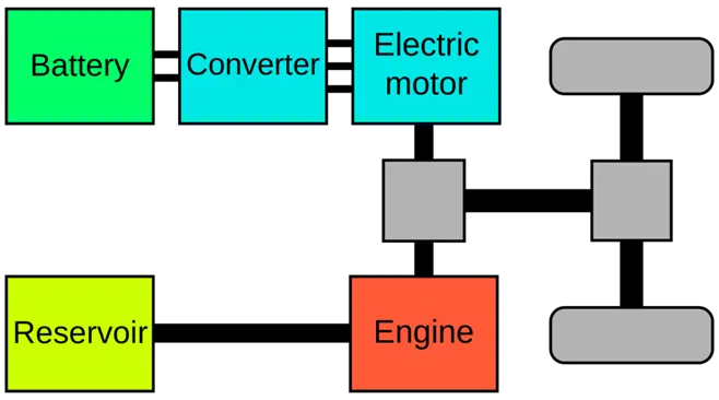
Fig 06. Parallel hybrid drive
Series Hybrid Powertrain:
Series hybrids are also referred to as extended-range electric vehicles (EREV) or range-extended electric vehicles (REEV), or electric vehicle with extended range (EVER). (Series hybrids with particular characteristics are classified as range-extended battery-electric vehicle (BEVx) by the California Air Resources Board.
Electric transmission has been available as an alternative to conventional mechanical transmissions since 1903. Typically mechanical transmissions impose many penalties, including weight, bulk, noise, cost, complexity and a drain on engine power with every gear-change, whether accomplished manually or automatically. Unlike ICEs, electric motors do not require a transmission.
In effect the entire mechanical transmission between the ICE and the wheels is removed and replaced by an electric generator, some cable and controls, and electric traction motors, with the benefit that the ICE is no longer directly connected to the demand.
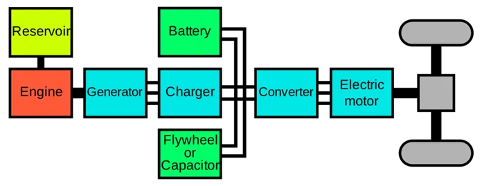
Fig 07. Series hybrid powertrain
Power Split or series parallel Drivetrains:
Power-split hybrid or series-parallel hybrid is parallel hybrids that incorporate power-split devices, allowing for power paths from the ICE to the wheels that can be either mechanical or electrical. The main principle is to decouple the power supplied by the primary source from the power demanded by the driver.
ICE torque output is minimal at lower RPMs and conventional vehicles increase engine size to meet market requirements for acceptable initial acceleration. The larger engine has more power than needed for cruising. Electric motors produce full torque at standstill and are well-suited to complement ICE torque deficiency at low RPMs. In a power-split hybrid, a smaller, less flexible, and more efficient engine can be used. The conventional Otto cycle (higher power density, more low-RPM torque, lower fuel efficiency) is often modified to an Atkinson cycle or Miller cycle (lower power density, less low-rpm torque, higher fuel efficiency; sometimes called an Atkinson-Miller cycle). The smaller engine, using a more efficient cycle and often operating in the favourable region of the brake specific fuel consumption map, significantly contributes to the higher overall efficiency of the vehicle.
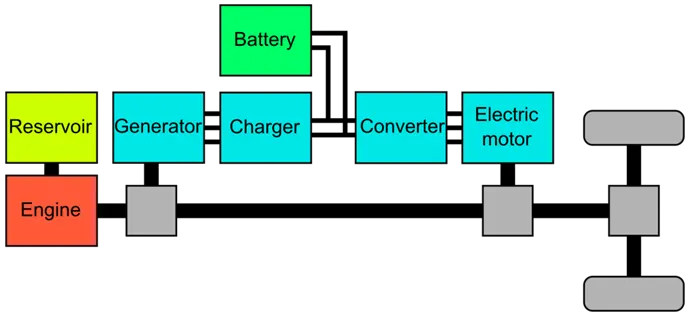
Fig 08. Series parallel powertrain
Hybrid vehicles can be used in different modes. The figure shows some typical modes for a parallel hybrid configuration.
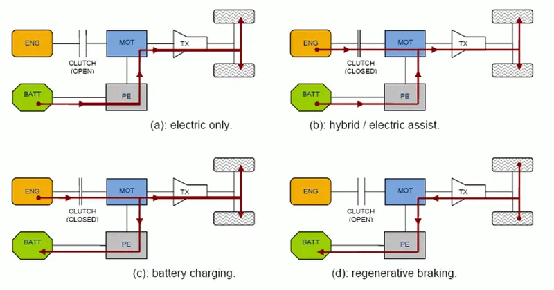
Fig 09. Different Hybrid Architecture
Key Components of Plugin Hybrid Electric vehicle
Battery (auxiliary): In an electric drive vehicle, the low-voltage auxiliary battery provides electricity to start the car before the traction battery is engaged; it also powers vehicle accessories.
Charge port: The charge port allows the vehicle to connect to an external power supply in order to charge the traction battery pack.
DC/DC converter: This device converts higher-voltage DC power from the traction battery pack to the lower-voltage DC power needed to run vehicle accessories and recharge the auxiliary battery.
Electric generator: Generates electricity from the rotating wheels while braking, transferring that energy back to the traction battery pack. Some vehicles use motor generators that perform both the drive and regeneration functions.
Electric traction motor: Using power from the traction battery pack, this motor drives the vehicle's wheels. Some vehicles use motor generators that perform both the drive and regeneration functions.
Exhaust system: The exhaust system channels the exhaust gases from the engine out through the tailpipe. A three-way catalyst is designed to reduce engine-out emissions within the exhaust system.
Fuel filler: A nozzle from a fuel dispenser attaches to the receptacle on the vehicle to fill the tank.
Fuel tank (gasoline): This tank stores gasoline on board the vehicle until it's needed by the engine.
Internal combustion engine (spark-ignited): In this configuration, fuel is injected into either the intake manifold or the combustion chamber, where it is combined with air, and the air/fuel mixture is ignited by the spark from a spark plug.
On-board charger: Takes the incoming AC electricity supplied via the charge port and converts it to DC power for charging the traction battery. It also communicates with the charging equipment and monitors battery characteristics such as voltage, current, temperature, and state of charge while charging the pack.
Power electronics controller: This unit manages the flow of electrical energy delivered by the traction battery, controlling the speed of the electric traction motor and the torque it produces.
Thermal system (cooling): This system maintains a proper operating temperature range of the engine, electric motor, power electronics, and other components.
Traction battery pack: Stores electricity for use by the electric traction motor.
Transmission: The transmission transfers mechanical power from the engine and/or electric traction motor to drive the wheels.
Advantages and disadvantages of Hybrid Drives:
Advantages:
- Environmental Friendly
One of the biggest advantages of a hybrid car over a gasoline-powered car is that it runs cleaner and has better gas mileage, which makes it environmentally friendly. A hybrid vehicle runs on a twin-powered engine (gasoline engine and electric motor) that cuts fuel consumption and conserves energy.
- Financial Benefits
Hybrid cars are supported by many credits and incentives that help to make them affordable. Lower annual tax bills and exemption from congestion charges come in the form of a smaller amount of money spent on fuel.
- Less dependency on fossil fuels
A Hybrid car is much cleaner and requires less fuel to run, which means fewer emissions and less dependence on fossil fuels. This, in turn, also helps to reduce the price of gasoline in the domestic market.
- Regenerative braking system
Each time you apply the brake while driving a hybrid vehicle, it helps you recharge your battery a little. An internal mechanism kicks in that captures the energy released and uses it to charge the battery, which in turn eliminates the amount of time and need for stopping to recharge the battery periodically.
- Built from light materials
Hybrid vehicles are made up of lighter materials, which mean less energy is required to run them. The engine is also smaller and lighter, which also saves much energy.
- Assistance from electric motor
The electric motor assists the internal combustion engine in case of accelerating, passing or climbing a hill.
- Smaller engines
The gasoline engines used in hybrid cars are usually small, light, and highly efficient as they don’t have to power the car alone.
- Automatic start and stop
In hybrid cars, the engine is automatically shut off when the vehicle is idle and starts when the accelerator is pressed. In comparison to traditional hybrid vehicles, PHEVs can drive longer distances at higher speeds. Hydrogen fuel cell vehicles have lower energy emissions because they emit only water vapour and warm air.
- Electric only drive
Hybrid vehicles can be driven entirely on electricity. This usually happens while moving at low speeds, when the engine is idling at a stoplight or when the engine starts up. Normally, the internal combustion engine starts operating only at higher speeds, where it has more efficiency. This helps increase the overall fuel efficiency of the vehicle.
Disadvantages:
- Less Power
Hybrid cars have twin-powered engines. The gasoline engine, which is the primary source of power, is much smaller as compared to what you get in single-engine powered cars, while the electric motor is of low power. The combined power of both is often less than that of a gas-powered engine. It is therefore suited for city driving and not for speed and acceleration.
- Can be Expensive
The biggest drawback of having a hybrid car is that it can burn a hole in your pocket. Hybrid cars are comparatively more expensive than regular petrol cars and can cost $5000 to $10000 more than a standard version. However, that extra amount can be offset with lower running costs and tax exemptions.
- Poorer handling
A hybrid car houses a gasoline-powered engine, a lighter electric engine, and a pack of powerful batteries. This adds weight and eats up the extra space in the car. Extra weight results in fuel inefficiency and manufacturers cut down weight, which has resulted in motor and battery downsizing and less support in the suspension and body.
- Higher maintenance cost
The presence of a dual engine and continuous improvement in technology make it difficult for mechanics to repair the car, and the cost of maintenance is also much higher. It is also difficult to find a mechanic with such expertise.
- Accidents from higher voltage batteries
In the event of an accident, the high voltage present inside the batteries can prove lethal for you. There is a high chance of you getting electrocuted in such cases, which can also make the task difficult for rescuers to get other passengers and the driver out of the car.
- Battery replacement is pricey
According to Green Car Reports, battery replacement in hybrid vehicles is currently rare. However, if a battery needs to be replaced, it can get pricey.
- Battery disposing and recycling
The batteries that are at the end of their useful life cycle can be recycled to harvest usable materials for repurposing. This removes waste from the environment. However, the main issue with recycling lies in the collection rate of vehicle batteries.
The same problem lies in recycling lithium batteries in mobile electronics. Although lithium is 100% recyclable, extracting it costs too much to make it of high economic value. It is only done because of federal mandates and/or ecological purposes.
Formula used for computation and modelling
Formula for calculating traction forces,
Aerodynamic drag acting on the vehicle
F_ad=1/2*ρ*A*C_d*V²
Where ρ is Density of air
A is Frontal area
C_d is Drag Coefficient
V is Velocity of vehicle
Rolling resistance force
F_rr=C_r*M*g*cosθ
Where C_r is a rolling coefficient
M is mass
Θ is slope angle
Grade Force
F_g=M*g*sinθ
Speed Ratio
SP=Ꙍt/Ꙍp
Where Ꙍt is turbine speed
Ꙍp is pump speed
Torque Ratio
TR=Tt/Tp
Where Tt is turbine torque
Tp is pump torque
Capacity Factor
Kf=Ꙍp/√Tp
Mass Fuel Rate consumption
Mf=Pe/(ⴄe*Q_LHV)
Where Pe is engine power
ⴄe engine efficiency
Q_LHV is low heat value of fuel
Relation between Ring gear, Sun gear and Carrier gear
Ꙍc*(Ns+Nr) = Ꙍs*Ns+Ꙍr*Nr
-Tc/(Ns+Nr)=Ts/Ns=Tr/Nr
Where c s and r represents carrier, sun and ring gear
Ꙍ is the speed
T is the torque
Project Overview
To model and execute the project we have divided into 3 structures they are,
- Matlab Initialization file
- Simulink model
- Post processing Matlab file
Matlab initialization file has the basic variable file which contains all the input data required for the simulink model. We run the initialization file to store the input data into workspace and from there we take data into simulink model.
Simulink model is the one which contain hybrid drive subsystem and model is executed to get the results. We use scope block to plot the possible graphs and data is again stored in matlab workspace for further processing.
Post processing matlab code takes all the results obtained after executing simulink model and these data is used to plot the required graph for further study using Matlab.
Matlab Initialization code:
%%%%%%%%%%%%%%%%%%%%%%%%%%%%%%%%%%%%%%%%%%%%%%%%%%%%%%%%%%%%%%%%%%%%%
%% Skill-Lync -> Hybrid Drives Development
% Project 2 - Hybrid Vehicle Model
% By - Shivakumar G R

% Description:

%% Initialization File
% Initialization file for loading the variables for the Conventional vehicle simulation model

%% Vehicle Parameters
M = 1500;       % Vehicle weight [kg]
Cr = 0.015;     % Rolling resistance coefficient
Rw = 0.35;      % Rolling radius [m]
Cd = 0.33;      % Drag coefficient
Af = 2;         % Frontal area [m2]
rhoa = 1.225;   % Air density [kg/m3]
Vwind = 0;      % Wind velocity [kmph]
g = 9.81;       % Gravitational acceleration [m/s2]
theta = 0;      % Slope [deg]
myu_road_tire = 1; % Coefficient of friction between tire - road interface

%% Powertrain Parameters
FDR = 3.73;                         % Final Drive Ratio / Diff Ratio
DiffEff = 0.99;                     % Differential efficiency (assumed independent of operating conditions)

NumGear = 4;                        % Number of gears in transmission
TransGear = [1:NumGear];            % Transmission Gears
TransRatio = [3.06, 1.62, 1, 0.7];  % Corresponding Transmission ratios
TransEff = 0.90;                    % Transmission efficiency (assumed independent of operating conditions)

TC_SR = [0, .5, .6, .7, .8, .87, .92, .94, .96, .97, 1];   % Torque Converter Speed Ratio (Matlab default) -> TurbSpd/PumpSpd
TC_TR = [2.232, 1.5462, 1.4058, 1.2746, 1.1528, 1.0732, 1.0192, 1, 1, 1, 1];   % Torque Converter Torque Ratio (Matlab default) -> TurbTrq/PumpTrq
TC_Cf = 1e-4 * [.72558, .66322, .63463, .59042, .51331, .4144, .29287, .22444, .12186, .04386, 0]; % Torque Converter Capacity Factor (Matlab default) -> PumpTrq/PumpSpd^2 [Nm/rpm^2]

load Vehicle_Data/Engine_data_1_9L_Saturn_95kW
load Vehicle_Data/Trans_Shift_map
load Vehicle_Data/EM_Honda_Insight_10kW
load Vehicle_Data/ESS_NiMH6


ESS_init_soc = 0.8;
ESS_soc_max = 0.9;
ESS_soc_min = 0.6;


%% Driver Parameters
Kp = 10;                    % P gain for driver PI model
Ki = 1;                     % I gain for driver PI model
Drive_Cycle_Select = 1;     % Drive cycle selection

% Drive cycle values in m/s

if Drive_Cycle_Select == 1
    load DriveCycles/UDDS;

elseif Drive_Cycle_Select == 2
    load DriveCycles/HWFET;

elseif Drive_Cycle_Select == 3
    load DriveCycles/FTP;

elseif Drive_Cycle_Select == 4
    load DriveCycles/US06;

elseif Drive_Cycle_Select == 5
    load DriveCycles/NEDC;

elseif Drive_Cycle_Select == 6
    load DriveCycles/WLTP;

end

time_end = cyc_time(end);
vel_end = cyc_vel(end);
Simulink Model:
We have brake the complex model structure into simpler subsystem for easy and better study. The outer structure of forward energy based hybrid drivetrain can be modeled as,
- Driver Unit
- Controller Unit
- Powertrain system
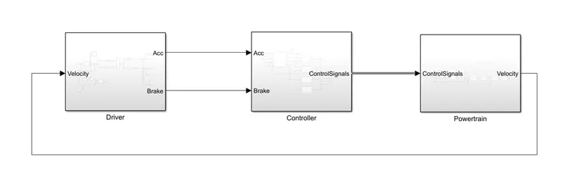
Fig 10. Simulink model of hybrid architecture
Driver:
The above system indicates the simulink model of forward energy based hybrid drive powertrain.
The driver unit basically generates acceleration and brake outputs for the control unit according to speed requirements.
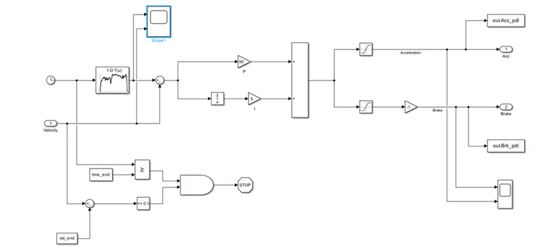
Fig 11 Driver Unit
Control Unit:
The above fig shows the driver models, the system takes drive cycle velocity and time as input, based on this the required acceleration and braking pedal are generated and given as output. We also have a system which stops the simulation when it completes the cycle.
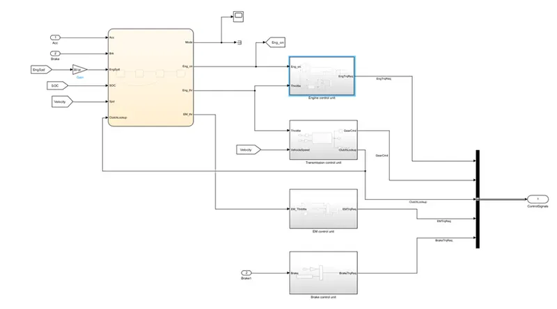
Fig 12 Controller Unit
The control unit takes acceleration and brake as input and generate the required signals for the powertrain block. Since it is hybrid vehicle we have energy source and we need to have a proper switching and ON OFF of each block according to driving conditions. So we have a mode selection block which decides the mode of operation (Start, Stop, Driving and Regen Braking). We use state flow method to model it.
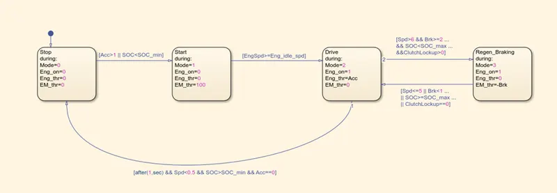
Fig 12.1 Mode selection
The mode selection block decides the condition of an engine and Electric motor. And signals are passed to the individual control units which generates the signals required for the powertrain block.
We have multiple control unit blocks as per the applications,
- Engine control unit
- Transmission control unit
- EM control unit
- Brake control unit
Engine control and EM control unit takes acceleration input and generate the required torque for respective blocks. They also take the engine and EM status according to mode selection based on that output is generated.
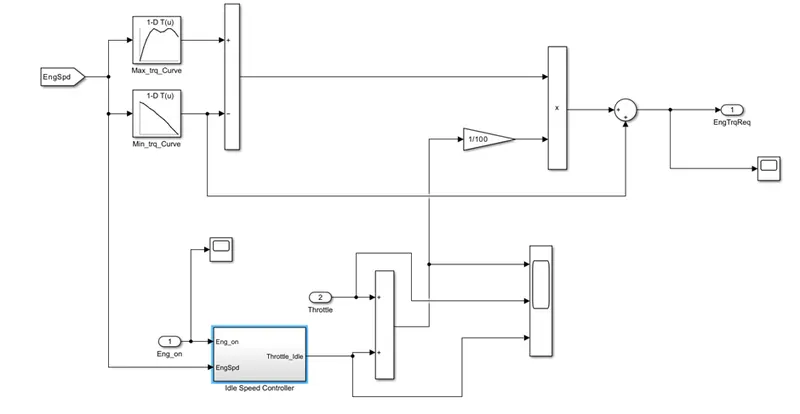
Fig 13. Engine control unit
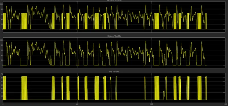
The engine control has idle control has idle control unit which generate the idle throttle.
Also we have EM control unit which generate the EM torque.
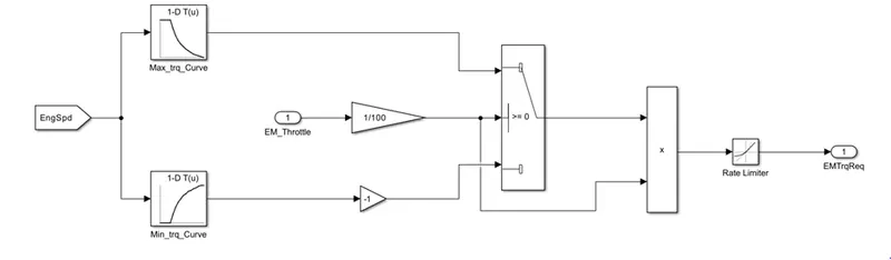
Fig 14. EM Control Unit
Similarly we have transmission control unit which generate the gear command. We use shift logic state flow method to set the gear command according to the speed.
Brake control unit take brake throttle input and generate brake torque.
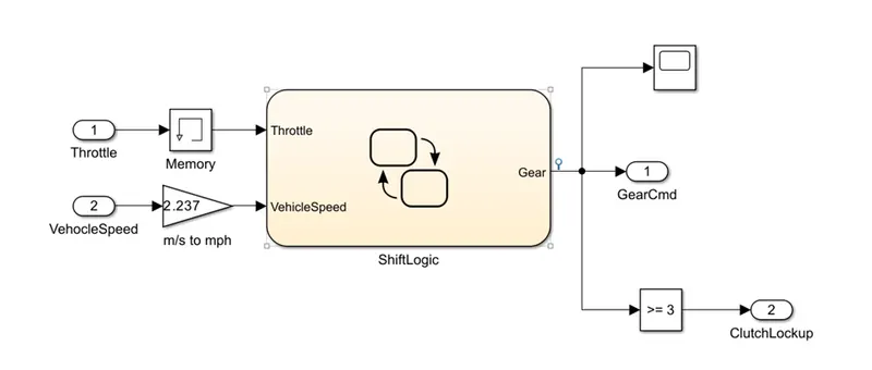
Fig 15. Transmission control Unit
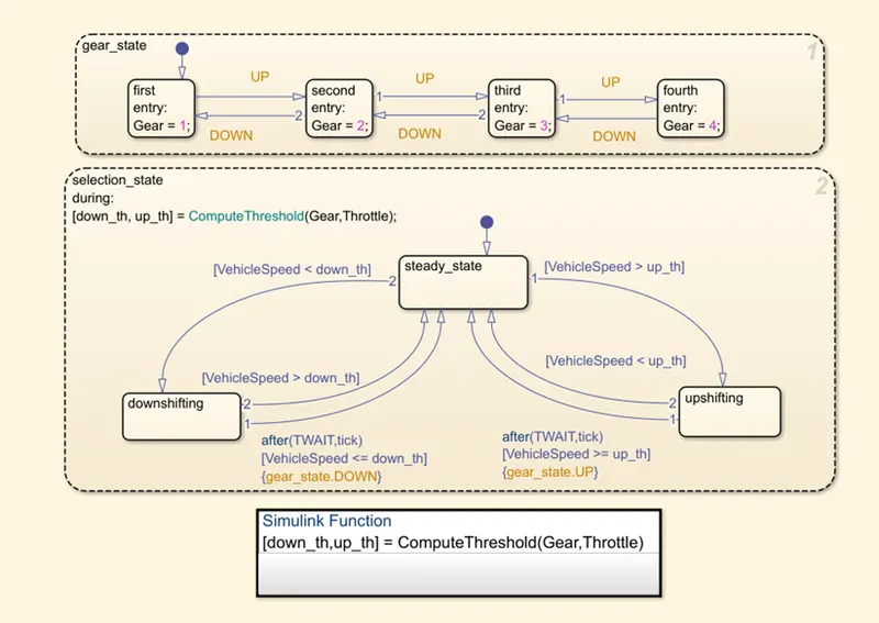
Fig 16 Shift Logic
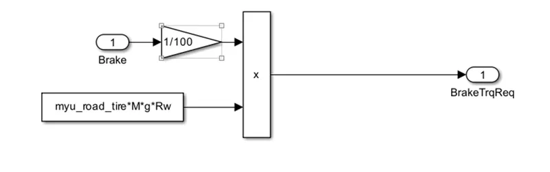
Fig 17. Brake control unit
Powertrain subsystem:
Powertrain has multiple subsystems according to working function. The subsystems are,
- Engine
- Electric motor
- Battery
- Transmission
- Differential
- Wheels
- Vehicle dynamics
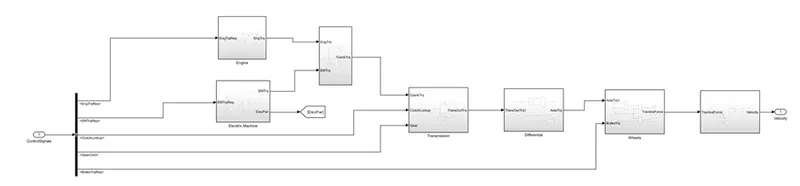
Fig 18. Hybrid vehicle powertrain system
Engine:
Engine is a power train unit block. Engine is called heart of the vehicle system and it is one which converts chemical energy stored in fuel into mechanical energy burning the fuel.
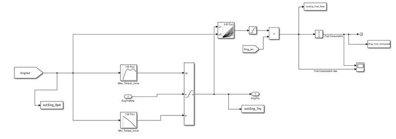
Fig 19. Simulink Engine model
Engine takes torque requirement as input and generates the torque that will be transmitted to transmission system. We use lookup tables to compute the torque generated from the engine. And use 2 D lookup table to compute the fuel economy. The look up table data is taken from matlab workspace. The computed fuel economy data is taken back into matlab to plot the results.
Electric Motor:
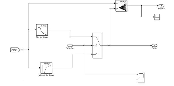
Fig 20. Simulink Electric Motor Model
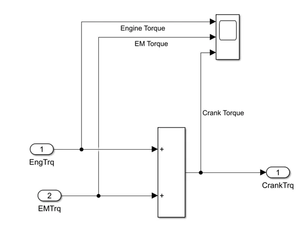
Fig 21. Simulink crank hub model
As we are modeling for hybrid vehicle we will have a additional energy source unit apart from engine. Here we are using electric power for the propulsion of a vehicle so we have a one more energy source. The above model shows the Electric motor model which generates the torque required while propulsion according to mode selection.
Fig 21 shows the crank hub which sums both the torque obtained from engine and E motor out gives output torque into transmission system.
Battery:
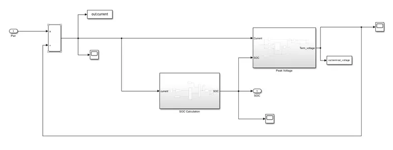
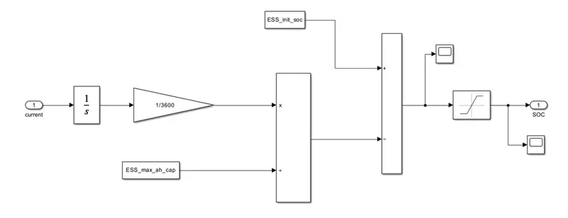
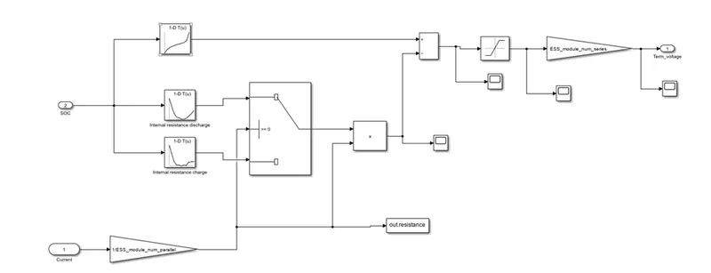
Battery is a electric power storage unit, and it delivers power hen it is required. System takes electric power as input to compute the state of charge and peak voltage.
Transmission:
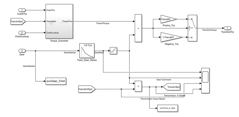
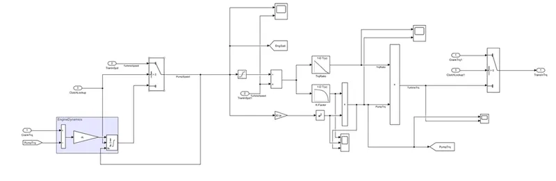
The transmission block takes engine torque as input and received by torque converter we get transmission input torque from it also we use the gear command to compute the required gear ratio and product of torque input and gear ration gives us output torque from transmission.
We have 1 D lookup table which takes the gear command and provides the corresponding gear ratio and torque output is multiplied with transmission efficiency to get accurate results.
Differential:
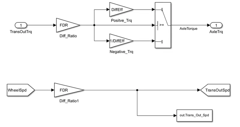
Fig 18. Simulink model of a differential
The transmission output torque is given as input to the differential system and this is multiplied by final drive ratio and differential efficiency to compute axle torque which is given to wheels for the traction.
Wheels:
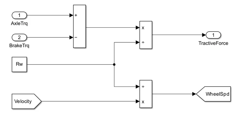
Fig 19. Simulink model of wheels
Wheels take axle torque and brake as input which is used to compute the tractive forces.
Vehicle dynamics:
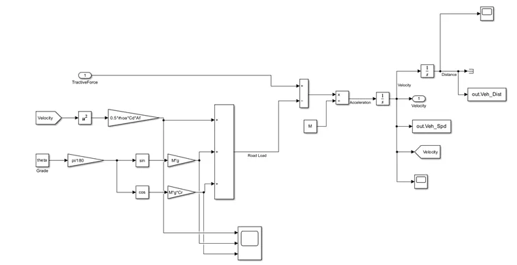
Fig 20. Simulink model of a vehicle Dynamics
A vehicle dynamics unit compute the required traction forces for the vehicle movement. There are different forces acting on the vehicle and all are calculated and added to calculate the final drive force, velocity and distance travelled.
The different types of traction forces acting are,
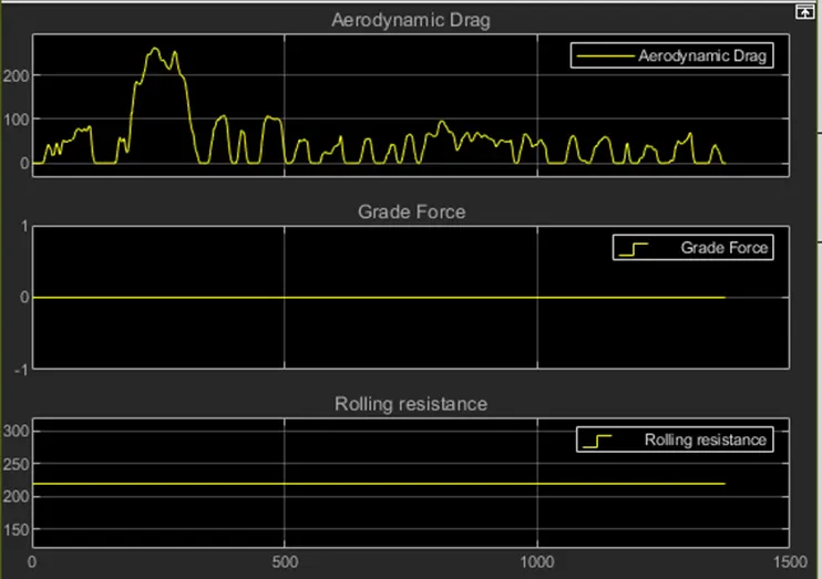
- Aerodynamic forces
- Rolling resistance
- Grade forces
All the forces are computed and divide by acceleration to calculate the velocity. Velocity is integrated at each time level to calculate the distance travelled.
At level of subsystem we have used scope to record the individual data and its variations. The same data has been imported back into workspace using to workspace block post processing purpose in matlab.
Post Processing Matlab Code:
%% Hybrid Drives Development
% Project 2 - P1 Hybrid Vehicle Model
% By - Shivakumar G R

%% Post-Processing File
%  File for post-processing the P1 Hybrid vehicle simulation model data

%% Renaming variables
Time = out.tout;
Acc_Pdl = out.Acc_Pdl;          % Accelerator pedal [%]
Brk_Pdl = out.Brk_Pdl;          % Brake pedal [%]
Gear_Cmd = out.Gear_Cmd;        % Transmission gear
Trans_In_Spd = out.Trans_In_Spd*30/pi;  % Transmission input speed [rpm]
Trans_Out_Spd = out.Trans_Out_Spd*30/pi;% Transmission output speed [rpm]
Eng_Trq = out.Eng_Trq;          % Engine brake torque [Nm]
Eng_Spd = out.Eng_Spd*30/pi;    % Engine speed [rpm]
Eng_Fuel_Consump = out.Eng_Fuel_Consumption;    % Engine fuel consumption [g]
Eng_Fuel_Rate = out.Eng_Fuel_Rate;   %engine fuel rate
Veh_Dist = out.Veh_Dist/1000;   % Distance traveled by vehicle [km]
Veh_Spd = out.Veh_Spd*18/5;     % Vehicle speed [kmph]
Whl_Spd = out.WheelSpd*30/pi;     % wheel speed[RPM]
Desired_spd = out.cycvelocity*18/5 ;  %desired speed [KMPH]
EM_Spd = out.EM_Spd*30/pi;         % E motor speed[rpm]
EM_Trq = out.EM_Trq;               % E motor torque[Nm]
EM_Pwr = out.EM_Pwr;               % E motor input power[W]
V_batt = out.terminal_voltage;              % battery pack voltage [V]
I_batt = out.current;              % battery pack current [I]
SOC = out.SOC;                     % STATE OF CHARGE [%]
RS = out.resistance;                       % internal resistance
VOC = out.opencircuit_voltage;     % open circuit voltage

%% Data Analysis
Eng_Pwr = Eng_Spd.*pi/30.*Eng_Trq/1000;   % Engine brake power [kW]
rho_petrol = 0.7197;                    % Density of petrol [kg/L]
kmpl = Veh_Dist(end)/(Eng_Fuel_Consump(end)/1000/rho_petrol);    % Fuel economy [kmpl];


% display fuel Economy of the cycle
%formatspec = 'fuel economy is %2.2f kmpl';
%fprintf(formatspec,kmpl);


%% Plotting vehicle characteristics time trace

% ploting transmission input,transmission output and wheel speed
figure(1)
hold on
grid on
plot(Time,Trans_In_Spd,'LineWidth',1,'Color','black');
plot(Time,Trans_Out_Spd,'LineWidth',1,'Color','red');
plot(Time,Whl_Spd,'LineWidth',1,'Color','blue');
xlabel('Time[s]')
ylabel('speed[rpm]')
xlim([0,Time(end)]);
legend('trans input','trans Output','wheel speed');
title('transmission input transmission output and wheel speed')

% plotting engine torque,engine power,fuel rate ,fuel consumption
figure(2)
subplot(4,1,1)
hold on
grid on
plot(Time,Eng_Trq,'LineWidth',1,'Color','black');
ylabel('torque[NM]')
xlim([0,Time(end)]);
title('Engine Torque')

subplot(4,1,2)
hold on
grid on
plot(Time,Eng_Pwr,'LineWidth',1,'Color','black');
ylabel('power[KW]')
xlim([0,Time(end)]);
title('Engine Power')

subplot(4,1,3)
hold on
grid on
plot(Time,Eng_Fuel_Rate,'LineWidth',1,'Color','black');
xlim([0,Time(end)]);
xlabel('Time[s]');
ylabel('Engine fuel rate');
title('Engine fuel rate')

subplot(4,1,4)
hold on
grid on
plot(Time,Eng_Fuel_Consump,'LineWidth',1,'Color','black');
xlim([0,Time(end)]);
xlabel('Time[s]');
ylabel('Engine fuel consumption[g]');
title('Engine Fuel Consumption')

% plotting accelerator and brake pedal gear command vehicle desired and actual speed ,vehicle distance
figure(3)

subplot(4,1,1)
hold on
grid on
plot(Time, Acc_Pdl, 'linewidth', 1, 'Color', 'black');
plot(Time, Brk_Pdl, 'linewidth', 1, 'Color', 'red');
ylabel('Pedal [%]')
xlim([0, Time(end)]);
legend('Accel','Brake');
title('Acceleration and brake pedal inputs')

subplot(4,1,2)
hold on
grid on
plot(Time, Veh_Spd, 'linewidth', 1, 'Color', 'black');
plot(Time, Desired_spd, 'linewidth', 1, 'Color', 'red');
ylabel('Speed [kmph]')
xlim([0, Time(end)]);
legend('actual speed','desired speed');
title('vehicle actual and desired speed')

subplot(4,1,3)
hold on
grid on
plot(Time, Veh_Dist, 'linewidth', 1, 'Color', 'black');
xlim([0, Time(end)]);
xlabel('Time [s]');
ylabel('distance[km]');
title('vehicle distance')

% plotting drive cycle
figure(4)
hold on
grid on
plot(cyc_time,cyc_vel,'LineWidth',1,'Color','black')
xlabel('time[s]')
ylabel('velocity[mph]')
title('drive cycle')

% test result
Avg_speed = sum(Veh_Spd)/length(Veh_Spd);
Max_speed = maxk(Veh_Spd,1);
table (Avg_speed,Max_speed,kmpl,'variablenames',{'average speed[kmph]','maximum speed[kmph]','fuel economy[kmpl]'})

%% Plotting engine operating points on engine fuel map
figure('Name','Engine Operating Points');
hold on
grid on
title('Engine Operating Points','fontsize',12);
plot(Eng_map_spd*30/pi,Eng_max_trq,'linewidth',2,'color','r');
p2=line([Eng_map_spd(end)*30/pi Eng_map_spd(end)*30/pi],[0 Eng_max_trq(end)]);
set(p2,'linewidth',1,'linestyle','--','color','k');
p3=line([Eng_map_spd(1)*30/pi Eng_map_spd(1)*30/pi],[0 Eng_max_trq(1)]);
set(p3,'linewidth',1,'linestyle','--','color','k');
[c,h] = contour(Eng_map_spd'*30/pi,Eng_map_trq,Eng_fuel_map');
clabel(c,h);
xlabel('Engine Speed [rpm]');
ylabel('Engine Torque [Nm]');
title('Engine Fuel Consumption Map [g/s]');
legend({'Max Curve','Operating Points'});
axis([Eng_map_spd(1)*30/pi Eng_map_spd(end)*30/pi 0 Eng_map_trq(end)]);

%% Electric Motor
% plotting motor speed ,motor torque,motor input power

figure(6)
subplot(3,1,1)
hold on
grid on
plot(Time,EM_Spd,'LineWidth',1,'Color','b');
ylabel('Speed[rpm]')
xlim([0,Time(end)]);
title('motor speed')

subplot(3,1,2)
hold on
grid on
plot(Time,EM_Trq,'LineWidth',1,'Color','r');
ylabel('torque[Nm]')
xlim([0,Time(end)]);
title('motor torque')

subplot(3,1,3)
hold on
grid on
plot(Time,EM_Pwr,'LineWidth',1,'Color','g');
ylabel('power[W]')
xlim([0,Time(end)]);
title('motor input power')

%% BATTERY
% plotting pack current,voltage,soc,internal resistance,open circuit
% voltage

figure(7)

subplot(5,1,1)
plot(Time,V_batt,'LineWidth',1,'Color','r');
xlabel('Time[sec]');
ylabel('voltage[v]');
title('pack voltage')
xlim([0,Time(end)]);
grid on

subplot(5,1,2)
plot(Time,I_batt,'LineWidth',1,'Color','b');
xlabel('Time[sec]');
ylabel('current[I]');
title('battery current')
xlim([0,Time(end)]);
grid on

subplot(5,1,3)
plot(Time,SOC,'LineWidth',1,'Color','g');
xlabel('Time[sec]');
ylabel('SOC[%]');
title('STATE OF CHARGE')
xlim([0,Time(end)]);
grid on

subplot(5,1,4)
plot(Time,RS,'LineWidth',1,'Color','r');
xlabel('Time[sec]');
ylabel('Internal resistance[ohm]');
title('Internal resistance')
xlim([0,Time(end)]);
grid on

subplot(5,1,5)
plot(Time,VOC,'LineWidth',1,'Color','b');
xlabel('Time[sec]');
ylabel('Open circuit voltage[v]');
title('Open circuit voltage')
xlim([0,Time(end)]);
grid on

%% Plotting engine operating points on engine fuel map
figure('Name','Electric motor Operating Points');
hold on
grid on
title('Electric motor Operating Points','fontsize',12);
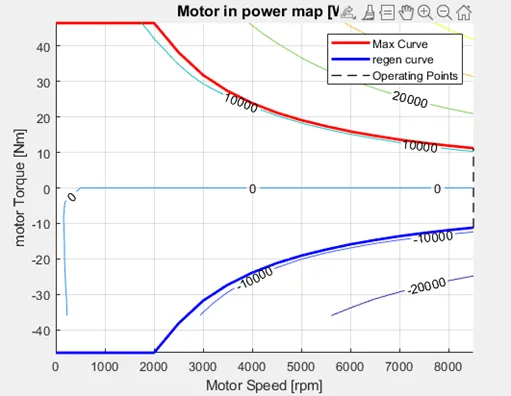
p1=plot(EM_map_spd*30/pi,EM_max_trq,'linewidth',2,'color','r');
p4=plot(EM_map_spd*30/pi,EM_max_gen_trq,'LineWidth',2,'Color','b');
p2=line([EM_map_spd(end)*30/pi EM_map_spd(end)*30/pi],[EM_max_gen_trq(end) EM_max_trq(end)]);
set(p2,'linewidth',1,'linestyle','--','color','k');
p3=line([EM_map_spd(1)*30/pi EM_map_spd(1)*30/pi],[EM_max_gen_trq(1) EM_max_gen_trq(1)]);
set(p3,'linewidth',1,'linestyle','--','color','k');
[c,h] = contour(EM_map_spd'*30/pi,EM_map_trq,EM_inpwr_map');
clabel(c,h);
xlabel('Motor Speed [rpm]');
ylabel('motor Torque [Nm]');
title('Motor in power map [W]');
legend([p1 p4 p3],{'Max Curve','regen curve','Operating Points'});
xlim([EM_map_spd(1)*30/pi EM_map_spd(end)*30/pi]);
ylim([EM_max_gen_trq(1) EM_max_trq(1)]);
Results:
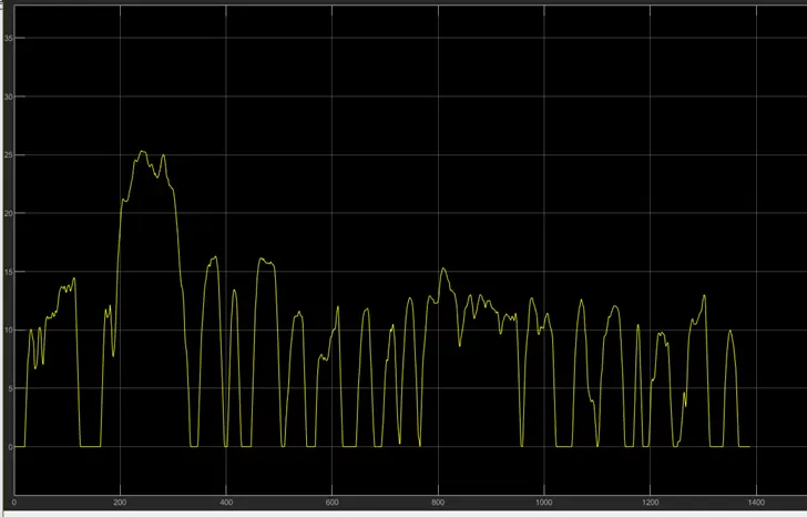
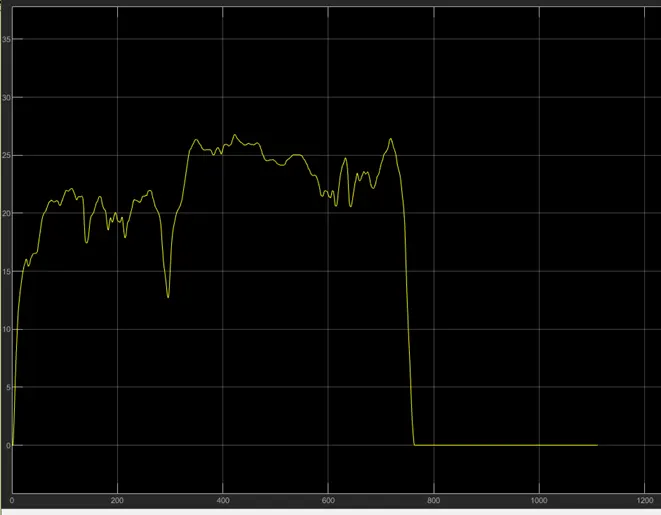
We will be discussing results obtained from simulink and matlab for both UDDS and HWFET Drive cycles one by one.
Velocity time graph
UDDS:
HWFET:
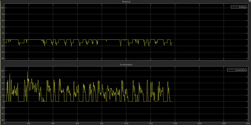
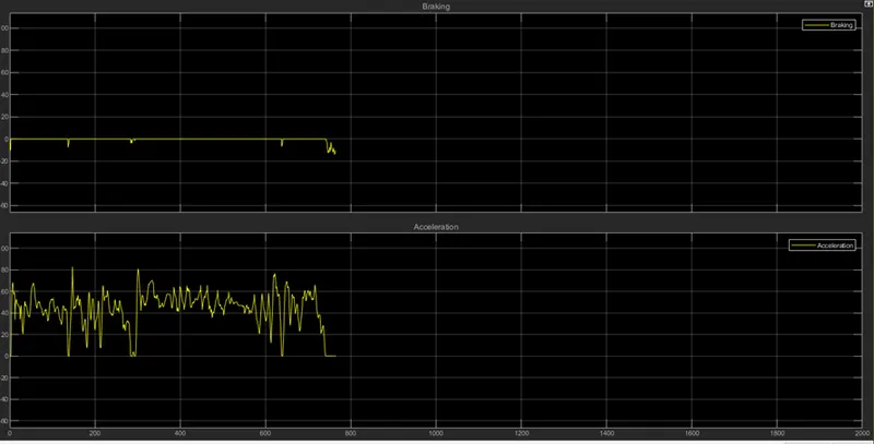
Acceleration and Braking:
UDDS:
HWFET:
Engine and idle throttle
UDDS:
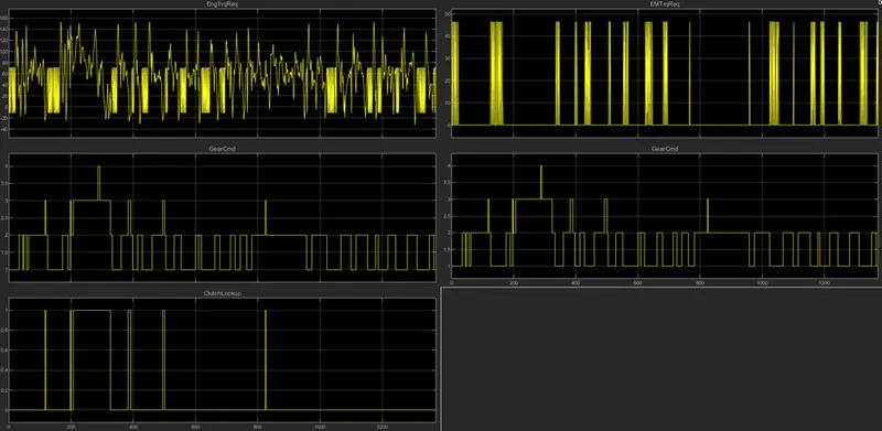
Engine Torque, Brake Torque Gear Command
UDDS:
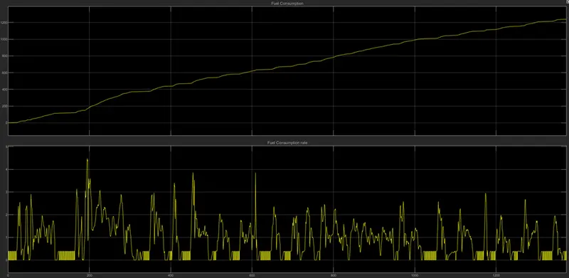
Fuel consumption:
UDDS:
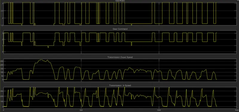
Gear ratio, Transmission input output torque
UDDS:
Traction forces acting on the vehicle body
UDDS:
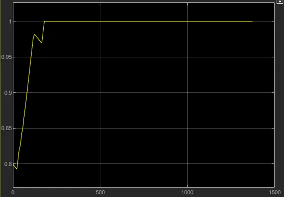
Battery SOC condition
UDDS:
Matlab Results:
Transmission Input output and wheel speed
Torque Power and engine fuel efficiency
Acceleration brake pedal, speed and distance
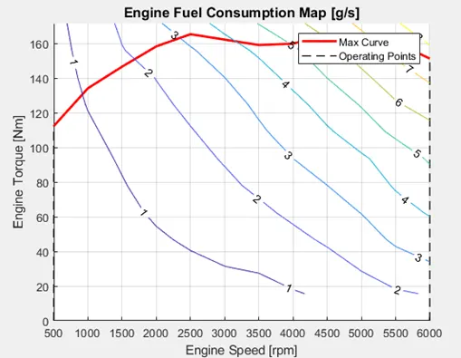
Engine fuel consumption and operating points
Motor Speed, Torque and Power
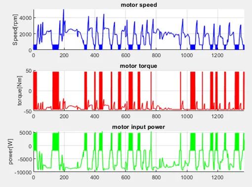
Motor Power and torque
Conclusions:
- We have obtained the graphs for both UDDS and HWFET drive cycles and images are saved.
- Observing velocity curve we can see a lot variation in velocity curve for UDDS cycle where as it is almost maintaining mean value in HWFET. So we can see very less brakes applied here where average acceleration is maintained.
- For UDDS cycle we can observe change of gear command within a short time interval where it is less in Highway cycle. Also Change of Gear s happening for higher velocity control in highway cycle, where for urban drive gear shifting is achieving for maintain lower speed.
- Fuel consumption rate is high for urban drive and where as it is maintained nominal in case of highway drive due to constant velocity and less braking. Overall fuel consumption for urban drive is more for covering shorter distance due to deceleration and braking.
The Detailed report is attched in pdf format with the project.
Below is the google drive link to download the file.
https://drive.google.com/drive/folders/1cQ90XE24HKcXxsC-ZnfDiS4LEqjy6mSl?usp=share_link
References:
- https://x-engineer.org/types-hybrid-electric-vehicles-hev/
- https://afdc.energy.gov/vehicles/how-do-plug-in-hybrid-electric-cars-work
- https://www.conserve-energy-future.com/advantages-and-disadvantages-of-hybrid-cars.php